A NOVEL SIW BPF BASED ON CIRCULAR
COMPLIMENTARY SPLIT RING RESONATORS FOR
MILLIMETER WAVE APPLICATIONS
S.KAREEMULLA1
1 Assistant Professor
Department of Electronics and Communication Engineering, MVJ college of Engineering, Channasandhra,
Bangalore-560067,India Email:[email protected].
M. PRAVEEN KUMAR*2, Dr.DN. SRI RAM KUMAR*3
2 PG Student, 3 Professor,
Department of Electronics and Communication Engineering, National Institute of Technology,
Thiruchirappalle,Trichy, Email: [email protected]. Abstract
A novel Substrate Integrated Waveguide Band Pass Filter based on circular complimentary split ring resonators (CSRR) is proposed in this paper. By etching Circular Complimentary Split Ring Resonators on the surface of the substrate integrated waveguide, the SIW gets BPF characteristics for particular band of frequencies. This ilter is small size and low proile, is useful in designing single substrate front-end broad band communication system. The current BPF is designed at 8 GHz to 9 GHz in X-Band and presented with Simulation results.
Key words - substrate integrated waveguide (SIW), via holes, Substrate integrated Circuit (SIC).
1. INTRODUCTION
As wireless communication relentlessly advances on frequency spectrum, there is great need for designing small size active and passive circuits at millimeter and microwave frequencies. These are mainly important for space application where space and weight are crucial factors. In this regard particularly ilters are always subject of great interest in millimeter and microwave frequency ranges since decades. As tremendous advancement has been seen in ields of left-handed metametirials and CSRR in planar conigurations has been used in many BPF designs in microstrip and other planar circuits for high performance and controlled characteristics.Though classical waveguide is in big size, but impressive with its high-Q in passive circuitry design. It is not preferable in today’s miniaturized electronic communications because of its bulk size and inability for post-tuning. Even planar waveguides like CPW, Microstrip are doing well still they are also limited in performance when it comes to high-Q performance and low losses are criteria.
Recently, SIW has been doing very well in microwave and millimetre ields with overwhelming contributions from academicians and researchers, because of their many advantages over other planar type waveguides and also for their low proile design. SIW technology is also compatible with many existing fabrication techniques like LTCC, HTCC technologies and possibly with MMIC methods. Importantly in fabrication, the design of metallic via should be properly taken care of.
2. DESIGN PROCEDURE
Figure 1. Basic SIW Structure with Design Parameters shown
A basic structure of SIW is shown in Fig. 1. It has mainly two rows of metallic vias on both sides of waveguide and with designing parameters diameter of via holes, separation between two successive holes and the separation between the rows of vias. These parameters are very crucial in designing low loss SIW. In order to design an SIW which will have low radiation loss, there are following suficient but not always necessary conditions.
D<λg/ 5 (1)
b
″
2
D
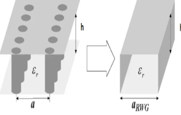
(2)In Design of SIW, b must be kept minimum for low radiation losses but D which is also subject of loss, also changes correspondingly with b. So it is the ratio of b and D crucial in design, not their individual values in case of low radiation loss design of SIW. To design the SIW in our desired frequency range there is equation for width and length for corresponding cut-off frequency. The SIW features high-pass characteristics; it was demonstrated in that a TE10-like mode in the SIW has dispersion characteristics that are almost identical with the mode of a dielectric illed rectangular waveguide with an equivalent width.
Effective
D
RWG
Width of SIW is
a =a- 2 b
0 95 / .
(3)
Cutoff
fc C r aRWG Frequency is
= /
(
2ε .)
(4)Complimentary Split ring Resonators have very interesting property in planar circuits that they are able to preclude signal in the vicinity of the resonant frequency, so that they have been used in BPF applications and others. So, By etching the CSRR on the face of SIW, it will provide negative permittivity for the structure, and signal will be stopped in the vicinity of resonant frequency. Firstly, an SIW has been designed to have very low radiation losses in the waveguide the above mentioned suficient conditioned are taken into consideration and designed. The designed parameters are given in table 1.
Figure 2. Substrate integrated wave guide and the equivalent classical rectangular waveguide.
If we alter the geometric parameters of the CSRR by decreasing the dimension in single cell, then the corresponding resonant frequency increases dramatically. Therefore to get resonant frequency at around 8GHz, the dimensions of CSRR has been slightly adjusted. The Signal is precluded in the vicinity of this particular resonant frequency the signal. The idea is to cascade CSRR such that we achieve required bandwidth in designed SIW BPF.
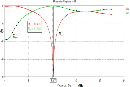
In simulation this single cell, as expected due to negative effective permittivity of the CSRR, the signal has been precluded in the vicinity of 8GHz which is its resonant frequency. The Fig.3. Shows the simulation results of both return and Insertion losses at 8GHz.
After designing the Single cell, the basic cells have been cascaded in order to form a BPF which will have broader bandwidth than the Single basic cell. The CSRRs have been loaded periodically on the face of SIW, but the edge CSRRs have been adjusted in size to get proper bandwidth, so their size is adjusted slightly to 1.7mm upper and 0.9mm lower circles. In this design, for simulation we used commercial EM simulation software “CST Microwave Studio”.
TABLE I. PARAMATERS OF THE PROPOSED SIW
Designing Parameters values
D 0.7 mm
b 1.4 mm
a 14 mm
Height(h) 0.26 mm
Figure 3. Photograph of the substrate integrated slotted-waveguide array antenna. a = 12:5 mm, b = 1:5 mm, p = 2 mm, and d = 1 mm. The transitional microstrip is 2.4 mm in width
When the Complimentary Split Ring Resonators are cascaded together as shown in the Fig.4, this gives SIW, Band Pass Characteristics in the range 8 to 9 GHz with very low return loss and insertion loss . This is because when the two adjusted CSRRs are placed besides the centre CSRR, they effectively spreaded the bandwidth that was observed in the Single Cell case.
Figure 4. Substrate integrated waveguide BPF with cascaded CSRR a = 14 mm, h = .26 mm, b = 2 mm, and D = 1 mm
Figure 5. Simulated Results for Retun Loss and Insertion Loss of SIW BPF
3. SIMULATION RESULTS
A substrate (Rogers RT 5880) with a relative permittivity of 2.2 and a loss tangent of tanδ = 0.009 is used
for the SIW Band Pass Filter simulation. CST Microwave Studio simulation tool which is developed by Finite Integration Technique is used for the simulation of the structure in given frequency range(4-10GHz).
TABLE II
Single Cell at 8 GHz Cascaded of Cells at 8.5 GHz
Return Loss -38.46 dB -22.05dB
Insertion Loss -0.15 dB -0.19 dB
4. CONCLUSION
A SIW Band Pass Filter based on circular CSRR has been presented, which is designed by cascading its single cells. The proposed BPF is small size, low proile and showing interesting results in the desired band with Return Loss and Insertion Loss at given frequencies. This design can be extended to design at other Microwave and millimeter frequency ranges. The presented BPF structure has been simulated in CST Microwave Studio simulation Tool.
REFERENCES
[1] Jordi Bonache, Ignacio Gil et al, “Novel Microstrip Bandpass Filters Based on Complementary Split-Ring Resonators,” IEEE transactions On Microwave Theory and Techniques, VOL. 54, pp 265-271, JANUARY 2006.
[2] Xiaochuan Zhang et al ,“Microstrip Wide Band-pass Filter Based on Substrate Integrated Waveguide (SIW),” IEEE International Symposium on Microwave, Antenna, Propagation, and EMC Technologies For Wireless Communications ,pp 209-211,,2007 [3] K. Wu, D. Deslandes, and Y. Cassivi “The Substratelntegrated Circuits-A New Concept for High-Frequency Electronics and
Optoeletronics”, Telecommunications in Modern Satellite, Cable and Broadcasting Service,2003. TELSIKS 2003. 6th International Conference , Volume: 1, Oct. 1- 3, 2003 Pages:P-III P-X.
[4] D. Deslandes and K. Wu, “Single substrate integration technique of planar circuits and waveguide ilters,” IEEE Trans. Micro -wave Theory Tech., vol. 51, pp. 593–596, Feb. 2003.
[5] Y. Cassivi, L. Perregrini, P. Arcioni, M. Bressan, K. Wu, and G. Conciauro.”Dispersion characteristics of substrate in tegrated rect -angular waveguide”, IEEE Microw. Wireless Compon. Lett, vol. 12, no. 9, pp. 333-335, Sep. 2002.
[6] Juan Domingo Baena, Jordi Bonache, Ferran Martín et al, “Equivalent- Circuit Models for Split-Ring Resonators and Complemen-tary Split- Ring Resonators Coupled to Planar Insertion Lines IEEE transactions On Microwave Theory and Techniques,,vol. 53, NO. 4,pp 1451-1461, April 2005
[7] D. Deslandes and K. Wu, “Integrated microstrip and rectangular wave guide in planar form,” IEEE Microwave Wireless Compon. Lett., vol.1, pp. 68–70, Feb. 2001.