Fabrication of Polymeric Coatings with
Controlled Microtopographies Using an
Electrospraying Technique
Qiongyu Guo1,2¤, Jason P. Mather2,3, Pine Yang2,3, Mark Boden4, Patrick T. Mather2,3 *
1Department of Macromolecular Science and Engineering, Case Western Reserve University, Cleveland, Ohio, United States of America,2Syracuse Biomaterials Institute, Syracuse University, Syracuse, New York, United States of America,3Department of Biomedical and Chemical Engineering, Syracuse University, Syracuse, New York, United States of America,4Boston Scientific Corporation, Marlborough, Massachusetts, United States of America
¤ Current address: Department of Plastic and Reconstructive Surgery, Johns Hopkins University School of Medicine, Baltimore, Maryland, United States of America
Abstract
Surface topography of medical implants provides an important biophysical cue on guiding cellular functions at the cell-implant interface. However, few techniques are available to pro-duce polymeric coatings with controlled microtopographies onto surgical implants, especial-ly onto implant devices of small dimension and with complex structures such as drug-eluting stents. Therefore, the main objective of this study was to develop a new strategy to fabricate polymeric coatings using an electrospraying technique based on the uniqueness of this technique in that it can be used to produce a mist of charged droplets with a precise control of their shape and dimension. We hypothesized that this technique would allow fac-ile manipulation of coating morphology by controlling the shape and dimension of electro-sprayed droplets. More specifically, we employed the electrospraying technique to coat a layer of biodegradable polyurethane with tailored microtopographies onto commercial coro-nary stents. The topography of such stent coatings was modulated by controlling the ratio of round to stretched droplets or the ratio of round to crumped droplets under high electric field before deposition. The shape of electrosprayed droplets was governed by the stability of these charged droplets right after ejection or during their flight in the air. Using the electro-spraying technique, we achieved conformal polymeric coatings with tailored microtopogra-phies onto conductive surgical implants. The approach offers potential for controlling the surface topography of surgical implant devices to modulate their integration with surround-ing tissues.
Introduction
Surface topography of medical implants plays an important role in regulating cellular func-tions, including cell adhesion, migration, and differentiation, through guiding cell-implant OPEN ACCESS
Citation:Guo Q, Mather JP, Yang P, Boden M, Mather PT (2015) Fabrication of Polymeric Coatings with Controlled Microtopographies Using an Electrospraying Technique. PLoS ONE 10(6): e0129960. doi:10.1371/journal.pone.0129960
Academic Editor:Donghui Zhu, North Carolina A&T State University, UNITED STATES
Received:January 19, 2015
Accepted:May 13, 2015
Published:June 19, 2015
Copyright:© 2015 Guo et al. This is an open access article distributed under the terms of theCreative Commons Attribution License, which permits unrestricted use, distribution, and reproduction in any medium, provided the original author and source are credited.
Data Availability Statement:All relevant data are within the paper and its Supporting Information files.
Funding:The authors received funding from Boston Scientific Corporation for this work. The funder had no role in study design, data collection and analysis, decision to publish, or preparation of the manuscript.
interactions [1–4]. A variety of fabrication techniques have been employed to make microscale topographies with patterned or randomly distributed structures. For instance, classical process-ing methods, such as plasma sprayprocess-ing [5], acid etching [6], machining [7], and sandblasting [8], have been intensively studied to produce randomly roughened surfaces on metallic materi-als. However, very few techniques are available for producing polymeric coatings with con-trolled roughness or topology onto surgical implants, especially onto implant devices with small dimensions and complex structures.
Polymeric coatings have been widely applied to medical devices in order to improve the de-vice performances in various aspects, including biocompatibility [9], biological functionaliza-tion [10], and controlled drug release [11–13]. For instance, drug-eluting stents (DES) have revolutionized percutaneous coronary intervention treatment by employing a thin layer of polymeric coating on the metallic stent struts for controlled drug release to reduce the rate of restenosis [14]. In the polymer-coated Taxus Paclitaxel-Eluting Stent (Boston Scientific, Na-tick, MA, USA), poly(styrene-b-isobutylene-b-styrene) (SIBS) triblock copolymers incorporat-ed with the drug of paclitaxel are coatincorporat-ed on the stent strut made by 316L stainless steel [15]. Nevertheless, the medical devices like DES invariably feature complicated architectures, pre-senting challenges for fabricating a polymeric coating on the devices with a controlled surface topography [13].
Recently, the electrospraying technique has received increasing attention for polymeric coating fabrication due to its facile controllability [16–19]. Electrospraying is an electrostatic processing method utilizing a high voltage under which a portion of a charged stationary liquid is ejected from the surface due to the electrical tension forces overcoming the surface tension force [20–23]. The charged liquid soon becomes unstable and breaks up into a mist of very fine charged droplets. The droplet size can be precisely controlled by electrospraying conditions with radii from hundreds of micrometers down to a few nanometers. Moreover, these droplets quickly dry in air and can undergo secondary breakup called Coulombic fission [24]. Here, electrostatic repulsion forces resulting from an increasing density of surface charges overcomes surface tension force. In addition, these charged droplets can target grounded conductive sub-strates, offering the potential to greatly increase the coating efficiency during conformal coat-ing. Compared to conventional coating techniques, the electrospraying technique is uniquely suited as a coating technique for medical device processing given: (1) the ability to target a con-ductive substrate of the electrosprayed charged droplets, and (2) the ability to control topogra-phy of the coating surface through controlling droplet shape and dimension.
This study focuses on developing a new strategy to utilize electrospraying technique to fabri-cate uniform polymeric coatings with tailored microtopographies on Express coronary stents. Recently, we have developed a group of polyhedral oligosilsesquioxane (POSS)-based polymers featuring unique chemical, physical and mechanical properties for various applications [25–
27]. A biodegradable POSS-based thermoplastic polyurethane (POSS TPU), which covalently incorporated POSS with poly(D, L-lactide) through urethane links, was employed in this work [28,29]. This polyurethane coated on such stents has been demonstrated to feature a highly adjustable controllability on the release of paclitaxel [30]. In the present study, two electro-spraying mechanisms were applied to control the microtopography of the polymeric coating on stent. Specifically, we tuned the electric field and flow rate of the polymer solution to manip-ulate either the primary breakup of the electrosprayed droplets right after ejection or the sec-ondary breakup of the droplets during their flight in the air before deposition. The primary breakup of these droplets was controlled by the geometrical forms of the polymer solution jet and was utilized to tune the ratio of round to stretched droplets. The secondary breakup of the charged droplets was determined by droplet evaporation and charge density and was employed to tailor the ratio of round to crumped droplets. The microtopography of the stent coating was Competing Interests:MB is an employee of Boston
then modulated by adjusting the ratio of round to stretched droplets or the ratio of round to crumped droplets. In addition, a high coating efficiency was obtained due to the targeting capa-bility of the electrosprayed droplets on the metallic stent.
Materials and Methods
Materials
Express Coronary Stents (16 mm length × 1.5 mm diameter) were kindly provided by Boston Scientific Corporation (Natick, MA, USA). The stent struts were smooth and made of 316L stainless steel. The mean roughness of the surface of bare metal stent is 4.3 ± 0.8 nm. The struts of the stents had a thickness of approximately 150μm and width around 80μm. Tetrahydrofu-ran (THF) and dimethylformamide (DMF) were purchased from Fisher and used as received. Polyhedral oligosilsesquioxane thermoplastic polyurethane (POSS TPU,M
n= 94.8 kg/mol,
Tg= 38°C,Tm= 112°C, H = 1.70 J/g) was used. Synthesis of the POSS TPU was carried out as
described earlier [28]. Briefly, this polymer was prepared by reacting a 12 kg/mol polyol (poly (D, L-lactide), PDLLA) with POSS diol using a lysine-derived diisocyanate (methyl 2,6-diiso-cyanatohexanoate, LDI) and typical urethane chemistry. The polyol was initiated by PEGM
n=
1 kg/mol and the mole feed ratio of POSS to polyol was 3.
Fabrication of polymeric coatings using electrospraying
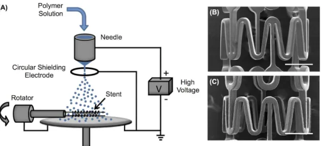
An electrospraying setup was designed to produce polymer droplets for fabricating polymeric coatings with tailored microtopographies on stents (Fig 1A). Specifically, a dilute polymer solu-tion of 0.5 wt% POSS TPU/THF was utilized for electrospraying unless otherwise specified. A small percentage of DMF was added in THF in the polymer solution, i.e. 0.5 wt% POSS TPU/ (THF:DMF = 95%:5%), to produce polymeric short fibers when controlling the microtopogra-phy of stent coating using different electrospraying modes as will be discussed below. A syringe pump (KD Scientific, Holliston, MA) was used to control the flow rate of the polymer solution in a 10 mL syringe (Hamilton, Reno, NV). A flow rate of 0.5 mL/h was applied unless otherwise specified. A programmable high voltage source (Ultravolt, Ronkonkoma, NY) was modulated
Fig 1. An electrospraying setup for stent-coating.(A) Schematic of an electrospraying setup for stent-coating using a circular shielding electrode placed right underneath the needle and above the aluminum plate. Continuous coating on Express coronary stent was achieved by exposed to the electrospraying mist for 30 min: (B) bare metal stent and (C) coated stent. Scale bar: 500μm.
by a DC power supply (Agilent E3630A, Newark, Chicago, IL). The positive electrode from the high voltage source was connected to the metal needle (304 stainless steel, Gauge 22, blunt nee-dle point, outer diameter of 0.72 mm, and inner diameter of 0.41 mm). A circular aluminum plate (dia. 5 cm) was grounded and centered underneath the needle with a needle tip-to-plate distance of 5 cm unless otherwise specified. A fresh aluminum film was wrapped over the alu-minum plate for each experiment to ensure good conductivity over the whole alualu-minum plate. In order to maintain stable droplet formation during electrospraying for some circumstances (indicated in the text below), a circular hoop-shaped shielding electrode (dia. 1.5 cm) made from a thin conductive wire (dia. 1 mm) was grounded and placed 0.5 cm below the needle. When used, the jet of droplets would traverse through the hoop toward the collector.
A stent rotation device was designed to support a stent using two stainless metal wires that spanned the length of each stent axially (Fig 1A). A needle tip-to-stent distance of 3.5 cm for stent coating by electrospraying was employed. The rotating stent supported on the two wires was grounded using a carbon brush dynamic contact. During stent coating, the stent was rotat-ed at 20 rpm and insertrotat-ed into the mist of electrosprayrotat-ed droplets for a prescribrotat-ed time up to 30 min, as detailed below.
Electrosprayed droplet analysis
Electrosprayed droplets collected on a cover glass (22 mm x 22 mm, Thermo Scientific, Pitts-burgh, PA) placed underneath the needle at distances from 3 cm up to 9 cm were examined by optical microscope (Olympus BX-51). Individual droplet sizes were determined using ImageJ (NIH) image analysis software. Deposited droplet size histograms were obtained on a total number of around 300 droplets at each condition.
Stent coating efficiency assessment
The stent coating efficiency was measured using a polymer solution of 0.5 wt% POSS TPU/ THF at a flow rate of 0.5 mL/h. The needle to-stent distance was 3.5 cm, and the needle tip-to-plate distance was 5 cm. A circular electrode with diameter of 1.5 cm was placed 0.5 cm below the needle. An electric field of 6.8 kV/cm was employed. A bare metal stent rotating at 20 rpm was inserted into the mist of electrosprayed droplets for 30 min. The coated stent was left to dry at room temperature overnight. The stent mass before and after coating was mea-sured three times using a Mettler-Toledo AX105 analytical balance (precision 0.01 mg, Colum-bus, OH). The average and standard deviation of coating efficiency were obtained based on six measurements acquired on different days.
Scanning electron microscopy (SEM)
The morphologies of the polymeric coatings on stents were examined using scanning electron microscopy (SEM, Hitachi S4500) at an accelerating voltage of 6 kV after being coated with a 10 nm layer of Pd.
Results and Discussion
Modulation of droplet dimension using electric field
stent inserted in the mist of the droplets, leading to a thin polymeric coating on the stent struts. As shown inFig 1B and 1C, a layer of polymer was uniformly coated on an Express coronary stent after being exposed to the electrosprayed droplets for 30 min.
The ejected polymer solution near the needle tip forms a meniscus, which may adopt differ-ent geometrical forms depending on the stability of the polymer solution jet [31]. When electric stresses are balanced with the other forces existing in the meniscus of the polymer solution jet, including surface tension force, gravity and viscosity force, the liquid meniscus assumes a Tay-lor cone geometry [32] and undergoes Rayleigh’s capillary breakup [33]. This mode is called cone-jet mode and has been widely applied to produce polymer particles with monodispersed size-distribution [17,34,35]. When the forces on the liquid meniscus cannot be balanced under electrospraying conditions, the liquid meniscus becomes unstable and transforms to shapes distinct from the Taylor cone geometry [20].
The electric field magnitude plays a critical role in determining various electrospraying modes through controlling the meniscus formation of ejected polymer solution from the nee-dle. When an electric field of 1.3 kV/cm was applied, the deposited droplets collected on a cover glass exhibited a diameter of 62 ± 22μm with a very broad size distribution under a micro-dripping mode (Fig 2A). When the electric field was increased to 1.4 kV/cm, the electro-spraying meniscus transformed to a spindle mode and the deposited droplets, compared to those under a micro-dripping mode, exhibited a diameter of 63 ± 9μm with a narrowed size distribution (Fig 2B). As shown inFig 2C, a cone-jet mode was obtained under the electric field of 1.5 kV/cm. The deposited droplets showed a smaller diameter of 51 ± 6μm with a further narrowed size distribution. A precession mode was observed at 1.6 kV/cm, yielding deposited droplets with a bimodal size distribution (Fig 2D). One set of the droplets collected under the precession mode exhibited a diameter of 39 ± 12μm, which is smaller than those under cone-jet mode. Another set of the deposited droplets with much smaller size (dia.<10μm) was also observed under the same precession mode. Therefore, the electrosprayed droplets coated on a substrate exhibited different shape and dimension under different electrospraying modes. Compared to the unstable electrospraying modes, the cone-jet mode was more controllable and produced droplets with dimensions of a narrower distribution. The geometries of the micro-dripping, spindle and precession modes are hemispherical, ellipsoidal and skewed cone, respectively.
Modulation of droplet dimension by controlling flow rate
Under a cone-jet mode, the flow rate of polymer solution can be used to precisely adjust the size of electrosprayed droplets. In order to maintain a cone-jet mode under different flow rates, a circular shielding electrode was designed to create a strong electric field near the tip of the needle. This circular shielding electrode can stabilize the liquid meniscus coming out of the needle, especially for low conductivity solutions [21,22]. As shown inFig 1, a circular electrode with diameter of 1.5 cm placed 0.5 cm below the needle was found to be capable of efficiently stabilizing the cone-jet mode at 6.8 kV/cm during electrospraying for a wide range of flow rates.
With the circular shielding electrode, we examined the impact of flow rate on the size of the deposited droplets while keeping the electric field constant at 6.8 kV/cm (Fig 3). For ideal liq-uids with low viscosity and low conductivity, the droplet size produced under cone-jet mode is expected to follow the relation [36],
r ½εε
0Q=K 1=3
ð1Þ
electrical permittivity of vacuum,Qisflow rate of the liquid, andKis electrical conductivity of the liquid. For a given polymer solution, its electrical permittivity and conductivity are both constant. Therefore, theflow rate is the only parameter available to control the size of electro-sprayed droplets. If we assume the droplet deforms from a spherical shape to a cylindrical shape with relatively constant thickness,h, upon deposition, we can calculate the diameter of the deposited droplet,d, based on mass conservation,
d¼ 16
3hr 3 1=2
r3=2
ð2Þ
then, we expect,
dQ1=2
ð3Þ
Fig 2. Deposited droplet size histogram obtained from different eletrospraying modes.Four eletrospraying modes were analyzed: (A) micro-dripping mode at electric field of 1.3 kV/cm, (B) spindle mode at electric field of 1.4 kV/cm, (C) cone-jet mode at electric field of 1.5 kV/cm, and (D) precession mode at electric field of 1.6 kV/cm. The optical microscopy images of the deposited droplets are shown in the inset Figs with scale bars of 100μm.
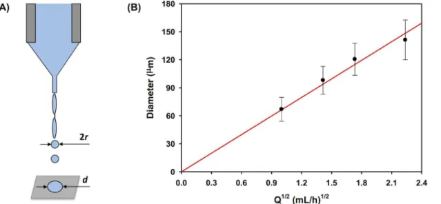
Indeed, as shown inFig 3B, the diameter of the deposited droplets shows a linear relation-ship withQ1/2, which confirms Eq (3) and applicability of Eq (1) to our conditions. Note that Fig 3Bexhibited slightly decreased diameter of deposited droplets as compared to the estimated value at a flow rate beyond 1.8 (mL/h)1/2. This is probably caused by a Marangoni instability [37–39], wherein the deposited droplets are still fluidic and dewetting in the droplets is trig-gered by surface tension. This happens when the droplets are too large to effectively dry right after their deposition on the collector. We have observed similar effect on stent coatings, which will be discussed later.
Modulation of droplet dimension by controlling droplet breakup
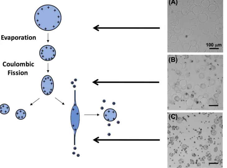
A unique phenomenon of charged polymer droplets produced from electrospraying is Cou-lombic fission: droplet breakup that occurs when electrostatic repulsion forces resulting from surface charge increase beyond the surface tension force of the droplets [24]. This happens in transporting electrosprayed droplets before they are collected due to the evaporation of the sol-vent from the droplets, which increasingly concentrates surface charge. In order to test for the Coulombic fission phenomenon, we placed the grounded aluminum plate 9 cm underneath the needle, employed a circular shielding electrode 0.5 cm below the needle, and collected the electrosprayed droplets at different distances from the needle using a cover glass. As shown in Fig 4, the electrosprayed droplets collected on the cover glass at different distances from the tip exhibited different morphologies. For a tip-to-collector distance of 3 cm, droplets with round edges were obtained, which indicates that Coulombic fission had not occurred in these drop-lets. When the tip-to-collector distance was increased to 6 cm, a fraction of the droplets broke into small pieces with ragged morphology. When the tip-to-collector distance increased further to 9 cm, only small, fragmented droplets with ragged morphology were obtained. Moreover, these droplets showed two quite distinct dimensions resulting from the breakup of the primary droplets due to Coulombic fission.
Fig 3. Formation of primary electrosprayed droplets.(A) Schematic diagram of the droplets formed from a jet through Rayleigh’s capillary breakup under a cone-jet mode during electrospraying process. (B) The diameter of deposited droplets vs. the square root of flow rate using the improved electrospraying setup with circular shielding electrode as shown inFig 1A.
Targeted coating on metallic stents by electrospraying
The positively charged electrosprayed droplets are unique in that they can target the grounded metallic stent and produce a continuous coating on the stent with a high coating efficiency. Here, the coating efficiency is calculated by,
Coating efficiency¼ Coating mass on the stent
Total mass of sprayed polymer100% ð4Þ
When a cone-jet mode was applied with the assistance of the ring electrode, the coating effi-ciency was controlled by the electrospraying setting, including the tip-to-stent distance and tip-to-plate distance. During electrospraying, the droplet spray area, which was mainly deter-mined by the repulsion and gravity forces of the charged electrosprayed droplets, was influ-enced by the tip-to-plate distance and tip-to-stent distance. When a tip-to-stent distance of 3.5 cm and tip-to-plate distance of 5 cm were applied, a spray area with diameter of 3 cm was ob-served and completely covered the stent (1.6 cm in length× 1.5 mm in diameter) fixed in space longitudinally. A further increase of the spray area by increasing the tip-to-plate distance
would lead to a decrease of the coating efficiency, whereas a decrease of the spray area could lead to uneven coating along the stent. When the spray area was fixed at 3 cm, the coating effi-ciency was found to be 31±5%. If we assume that the electrosprayed droplets would be deposit-ed in the spray area uniformly, the coating efficiency would equal the ratio of the area of the stent to the spray area at the same horizontal plane. This resulted in an estimated coating effi-ciency as low as 3%, which is a ten-fold lower than the coating effieffi-ciency we obtained. This in-dicates that the charged droplets produced from electrospraying targeted the grounded stent, leading to a dramatically increased coating efficiency.
Microtopography control of stent coating by electrospraying modes
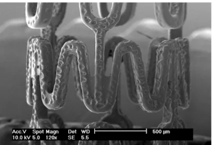
Stent coatings with controlled microtopographies were obtained from electrosprayed droplets produced using different electrospraying modes, as shown inFig 5. Continuous stent coatings with smooth topography were obtained when the deposited droplets (dia. 30–60μm) were formed using a cone-jet mode obtained at an electric field of 1.5 kV/cm (Fig 5A). A precession mode was derived at 1.6 kV/cm and 1.7 kV/cm, separately. As shown inFig 5B, a combination of round and stretched droplets were produced and simultaneously coated on the stent, resulting in a layer of roughened polymeric coating. The stretched droplets appear as short fibers due to their high aspect ratios. Importantly, compared to the stent coating obtained at 1.6 kV/cm (Fig 5B1), the increased electric field of 1.7 kV/cm (Fig 5B2) produced a higher ratio of stretched to round droplets and higher aspect ratio of the stretched droplets in the coating. Under a multi-jet mode at 1.8 kV/cm, only stretched droplets were formed and deposited on the stent surface, yielding a fibrous structure on the stent coating (Fig 5C). These short fibers deposited on stent are distinct from conventional electrospun nanofibers with an infinite aspect ratio [40], which are unable to continuously coat the stent surface without covering the empty spaces between stent struts.We observed that the morphology of electrosprayed droplets coated on stent surfaces was slightly different from those deposited on glass slide. This may be explained by the change of local electric field around the stent resulting from insertion of the stent in the coating appara-tus, itself. In addition, electrosprayed droplets too large in size (dia.>100μm) are not suitable for stent coating due to the small dimension of each stent strut (width ~150μm). The polymer droplets could specifically accumulate along the edge and across the corner of the stent struts, leading to non-uniform coatings with large pores on the stent (Fig 6). This phenomenon relates to the Marangoni instability [37–39], wherein dewetting of liquid coatings is caused by surface tension gradients. This is applicable in our process when the coating is still fluid after the depo-sition of the electrosprayed droplets on the stent.
Fig 5. Coating morphology obtained at different electrospraying modes.SEM images of Express coronary stents coated by electrosprayed droplets obtained at different electrospraying modes: (A) cone-jet mode, (B) precession mode, and (C) multi-jet mode. These electrospraying modes were achieved at an increasing electric field of (A) 1.5 kV/cm, (B1) 1.6 kV/cm, (B2) 1.7 kV/cm, and (C) 1.8 kV/cm, respectively. Round and stretched deposited droplets were highlighted in empty yellow triangles (A) and solid yellow triangles (B), respectively.
Microtopography control of stent coating by Coulombic fission
The adjustment of the microtopographies of stent coatings was accomplished by changing the ratio of crumpled droplets to smooth droplets formed by Coulombic fission using electrospray-ing technique under a cone-jet mode stabilized by a circular shieldelectrospray-ing electrode. As shown in Fig 7, the roughness of stent coatings increased as the volumetric flow rate,Q, decreased gradu-ally from 0.5 mL/h to 0.2 mL/h.Fig 7A, withQ= 0.5 mL/h, reveals a smooth surface morpholo-gy, whereasFig 7D, whileQ= 0.2 mL/h results in a web-like coating on the stent. This could be attributed to the increasing instability of electrosprayed droplets at decreasing flow rate. As we discussed previously, the electrosprayed droplets become unstable and undergo Coulombic fis-sion to be deformed or split when their electrostatic repulfis-sion increased beyond the surface tension during their transport in the air before collected. The smaller the droplets produced from the Taylor cone, the higher surface-to-volume ratio of the droplets, and the higher the evaporation rate of the solvent in the droplets. The result is less stable droplets. Therefore, as we decreased the solution flow rate, the size of the electrosprayed droplets also reduced, leading to more unstable and rough droplets collected on the stent.Fig 6B and 6Cobtained for coatings produced at flow rates of 0.4 mL/h and 0.3 mL/h, respectively, clearly exhibit both of the crum-pled droplets and smooth droplets on the stent coatings. All stent coatings shown in Figs5–7 feature uniform surface topography in the whole stent.
Conclusions
In this study, we presented a new strategy to employ the electrospraying technique to fabricate polymeric coatings with varying microtopographies on coronary stents. We systematically in-vestigated tuning electrospraying processing conditions, including electric field, flow rate and tip-to-collector distance, to manipulate the primary breakup and secondary breakup of the electrosprayed droplets for stent coatings. Different mechanisms of the electrospraying tech-nique were employed to precisely control the droplet formation, droplet dimension and droplet breakup. Smooth stent coatings were achieved using the proper droplet size between 30 to 60μm under cone-jet mode before Coulombic fission happens. The microtopography of stent Fig 6. SEM image of a stent coated with large electrosprayed droplets (dia. ~120μm).A non-uniform
coating was varied conveniently by the electrospraying technique utilizing different electro-spraying modes with or without Coulombic fission. Drugs can also be easily incorporated into the polymeric coating by electrospraying polymer solutions containing dissolved drugs [30, 41]. Therefore, the electrospraying technique was proven to be suitable to produce coating on electrically conductive surgical implants, and can be argued to be superior to both dip coating and air-brush spraying techniques in terms of surface topography control and coating efficien-cy. Enhancing stent coating surface topography can potentially modulate surface properties such as surface energy and wettability, which directly impact protein absorption and cell re-sponses at the interface between the implant and host tissue. The great potential of this electro-spraying technique has been only evaluated in limited research explorations, but undoubtedly deserves deeper attention in various biomedical applications from a small scale of microstruc-tured particles to a large scale of bioscaffolds, and from pre-defined processing to in-situ cus-tom-designed treatments.
Supporting Information
S1 Data. Deposited droplet size distribution data represented inFig 2. (XLSX)
Fig 7. Coating morphology controlled by Coulombic fission.SEM images of Express coronary stents coated by electrosprayed droplets obtained at different flow rates with varying degree of Coulombic fission: (A) 0.5 mL/h, (B) 0.4 mL/h, (C) 0.3 mL/h, and (D) 0.2 mL/h.
S1 Table. P value comparison of deposited droplet diameters obtained from different ele-trospraying modes represented inFig 2.
(XLSX)
Acknowledgments
The authors would like to thank Dr. Pamela T. Knight for her assistance of polymer synthesis for this work.
Author Contributions
Conceived and designed the experiments: QG MB PTM. Performed the experiments: QG JPM PY. Analyzed the data: QG JPM PY. Contributed reagents/materials/analysis tools: MB PTM. Wrote the paper: QG JPM MB PTM PY.
References
1. Bettinger CJ, Langer R, Borenstein JT. Engineering substrate topography at the micro- and nanoscale to control cell function. Angew Chem Int Ed. 2009; 48(30):5406–15. doi:10.1002/Anie.200805179 PMID:19492373
2. Nikkhah M, Edalat F, Manoucheri S, Khademhosseini A. Engineering microscale topographies to con-trol the cell-substrate interface. Biomaterials. 2012; 33(21):5230–46. Epub 2012/04/24. doi:10.1016/j. biomaterials.2012.03.079PubMed Central PMCID: PMC3619386. PMID:22521491
3. Ross AM, Jiang ZX, Bastmeyer M, Lahann J. Physical Aspects of Cell Culture Substrates: Topography, Roughness, and Elasticity. Small. 2012; 8(3):336–55. doi:10.1002/Smll.201100934PMID:22162324 4. Gittens RA, Olivares-Navarrete R, Cheng A, Anderson DM, McLachlan T, Stephan I, et al. The roles of titanium surface micro/nanotopography and wettability on the differential response of human osteoblast lineage cells. Acta Biomater. 2013; 9(4):6268–77. doi:10.1016/J.Actbio.2012.12.002PMID:23232211 5. Huang Y, Song L, Liu XG, Xiao YF, Wu Y, Chen JY, et al. Hydroxyapatite coatings deposited by liquid
precursor plasma spraying: controlled dense and porous microstructures and osteoblastic cell re-sponses. Biofabrication. 2010; 2(4):045003. doi:10.1088/1758-5082/2/4/045003PMID:21076187 6. Oliveira DP, Palmieri A, Carinci F, Bolfarini C. Osteoblasts behavior on chemically treated commercially
pure titanium surfaces. Journal of biomedical materials research Part A. 2014; 102A:1816–22. Epub 2013/06/21. doi:10.1002/jbm.a.34855
7. Anselme K, Bigerelle M, Noel B, Iost A, Hardouin P. Effect of grooved titanium substratum on human osteoblastic cell growth. J Biomed Mater Res. 2002; 60(4):529–40. doi:10.1002/Jbm.10101PMID: 11948511
8. Kunzler TP, Drobek T, Schuler M, Spencer ND. Systematic study of osteoblast and fibroblast response to roughness by means of surface-morphology gradients. Biomaterials. 2007; 28(13):2175–82. doi:10. 1016/J.Biomaterials.2007.01.019PMID:17275082
9. Morais JM, Papadimitrakopoulos F, Burgess DJ. Biomaterials/tissue interactions: possible solutions to overcome foreign body response. AAPS J. 2010; 12(2):188–96. doi:10.1208/s12248-010-9175-3 PMID:20143194
10. Knoll W, Bender K, Forch R, Frank C, Gotz H, Heibel C, et al. Polymer-Tethered Bimolecular Lipid Membranes. Adv Polym Sci. 2010; 224:87–111. doi:10.1007/12_2009_27
11. Fuchs T, Schmidmaier G, Raschke MJ, Stange R. Bioactive-coated implants in trauma surgery. Eur J Trauma Emerg S. 2008; 34(1):60–8. doi:10.1007/s00068-006-6110-5
12. Liu Y, Wu G, de Groot K. Biomimetic coatings for bone tissue engineering of critical-sized defects. J R Soc Interface. 2010; 7 Suppl 5:S631–47. Epub 2010/05/21. doi:10.1098/rsif.2010.0115.focusPMID: 20484228
13. Puskas JE, Munoz-Robledo LG, Hoerr RA, Foley J, Schmidt SP, Evancho-Chapman M, et al. Drug-eluting stent coatings. WIREs Nanomed Nanobiotechnol. 2009; 1(4):451–62. Epub 2010/01/06. doi: 10.1002/wnan.38PMID:20049810
15. Grube E, Silber S, Hauptmann KE, Mueller R, Buellesfeld L, Gerckens U, et al. Six- and twelve-month results from a randomized, double-blind trial on a slow-release paclitaxel-eluting stent for de novo coro-nary lesions. Circulation. 2003; 107(1):38–42. PMID:12515740
16. Uematsu I, Matsumoto H, Morota K, Minagawa M, Tanioka A, Yamagata Y, et al. Surface morphology and biological activity of protein thin films produced by electrospray deposition. J Colloid Interf Sci. 2004; 269(2):336–40. doi:10.1016/J.Jcis.2003.08.069PMID:14654393
17. Kumbar SG, Bhattacharyya S, Sethuraman S, Laurencin CT. A preliminary report on a novel electro-spray technique for nanoparticle based biomedical implants coating: Precision electroelectro-spraying. J Biomed Mater Res B. 2007; 81B(1):91–103. doi:10.1002/Jbm.B.30641
18. de Jonge LT, Leeuwenburgh SCG, van den Beucken JJJP, Wolke JGC, Jansen JA. Electrosprayed en-zyme coatings as bioinspired alternatives to bioceramic coatings for orthopedic and oral implants. Adv Funct Mater. 2009; 19(5):755–62. doi:10.1002/adfm.200800819
19. Yohe ST, Grinstaff MW. A facile approach to robust superhydrophobic 3D coatings via connective-parti-cle formation using the electrospraying process. Chem Commun. 2013; 49(8):804–6. doi:10.1039/ C2cc38012aPMID:23235806
20. Jaworek A, Krupa A. Classification of the modes of EHD spraying. J Aerosol Sci. 1999; 30:873–93. 21. Jaworek A. Micro- and nanoparticle production by electrospraying. Powder Technol. 2007; 176:18–35. 22. Jaworek A, Sobczyk AT. Electrospraying route to nanotechnology: an overview. J Electrostat. 2008;
66:197–219.
23. Guo Q, Aly A, Schein O, Trexler MM, Elisseeff JH. Moxifloxacin in situ gelling microparticles– bioadhe-sive delivery system. Results Pharma Sci. 2012; 2:66–71. doi:10.1016/j.rinphs.2012.09.002PMID: 25755996
24. Duft D, Achtzehn T, Muller R, Huber BA, Leisner T. Coulomb fission—Rayleigh jets from levitated microdroplets. Nature. 2003; 421(6919):128-. doi:10.1038/421128aPMID:12520291
25. Wu J, Mather PT. POSS Polymers: Physical Properties and Biomaterials Applications. Polym Rev. 2009; 49(1):25–63. doi:10.1080/15583720802656237PMID:19557697
26. Gu X, Wu J, Mather PT. Polyhedral oligomeric silsesquioxane (POSS) suppresses enzymatic degrada-tion of PCL-based polyurethanes. Biomacromolecules. 2011; 12(8):3066–77. doi:10.1021/bm2006938 PMID:21675705
27. Huitron-Rattinger E, Ishida K, Romo-Uribe A, Mather PT. Thermally modulated nanostructure of poly(ε-caprolactone)–POSS multiblock thermoplastic polyurethanes. Polymer. 2013; 54:3350–62. doi:10. 1167/iovs.13-11831PMID:23580486
28. Knight PT, Lee K, Qin H, Mather PT. Biodegradable thermoplastic polyurethanes incorporating polyhe-dral oligosilsesquioxane. Biomacromolecules. 2008; 9:2458–67. doi:10.1021/bm8004935PMID: 18698847
29. Knight PT, Kirk JT, Anderson JM, Mather PT. In vivo kinetic degradation analysis and biocompatibility of aliphatic polyester polyurethanes. Journal of biomedical materials research Part A. 2010; 94(2):333–
43. Epub 2010/06/29. PMID:20583334
30. Guo Q, Knight PT, Mather PT. Tailored drug release from biodegradable stent coatings based on hybrid polyurethanes. J Control Release. 2009; 137(3–4):224–33. doi:10.1016/j.jconrel.2009.04.016PMID: 19520124
31. Ijsebaert JC, Geerse KB, Marijnissen JCM, Lammers JWJ, Zanen P. Electro-hydrodynamic atomization of drug solutions for inhalation purposes. J Appl Physiol. 2001; 91:2735–41. PMID:11717241
32. Taylor G. Disintegration of water drops in an electric field. Proc R Soc Lond Ser A Math Phys Sci. 1964; 280:383–97.
33. Tang K, Gomez A. On the Structure of an Electrostatic Spray of Monodisperse Droplets. Phys Fluids. 1994; 6(7):2317–32.
34. Nath SD, Son S, Sadiasa A, Min YK, Lee BT. Preparation and characterization of PLGA microspheres by the electrospraying method for delivering simvastatin for bone regeneration. Int J Pharm. 2013; 443 (1–2):87–94. doi:10.1016/J.Ijpharm.2012.12.037PMID:23333756
35. Yu DG, Williams GR, Wang X, Liu XK, Li HL, Bligh SWA. Dual drug release nanocomposites prepared using a combination of electrospraying and electrospinning. Rsc Adv. 2013; 3(14):4652–8. doi:10. 1039/C3ra40334c
36. de Juan L, de la Mora JF. Charge and size distributions of electrospray drops. J Colloid Interface Sci. 1997; 186:280–93. PMID:9056353
37. Weh L, Venthur A. Crack patterns in thin polymer layers Macromol Mater Eng. 2004 289:227–37. 38. Hu H, Larson RG. Marangoni effect reverses coffee-ring depositions J Phys Chem B 2006 110:7090–4
39. Nikolov AD, Wasan DT, Chengara A, Koczo K, Policello GA, Kolossvary I. Superspreading driven by Marangoni flow. Adv Colloid Interface Sci. 2002; 96:325–38 PMID:11908793
40. Tseng LF, Mather PT, Henderson JH. Shape-memory-actuated change in scaffold fiber alignment di-rects stem cell morphology. Acta Biomater. 2013; 9(11):8790–801. doi:10.1016/j.actbio.2013.06.043 PMID:23851156