The challenge of uncertainty and ambiguity is ubiquitous in the development of complex systems and needs to be faced. The all-embracing integration of specialists from multiple disciplines is proven to be a major challenge in the product engineering process.
This article presents the experiences and advancements made within one year of explorative industrial application of an integrated technique for sustainable, multidisciplinary model-based systems engineering. The technique consists of two main partitions: the consistent specification of objectives and requirements on the one hand and a function-based modeling technique for the according System Architecture using the Contact & Channel – Approach (C&C²-A) on the other hand. Embedding it into the integrated Product engineering Model (iPeM) provides a capable and flexible guideline for managers and engineers.
This article starts with a short introduction to Model-based Systems Engineering (MBSE) and the most popular modeling language SysML, followed by an outline of current challenges in application. After a brief summary of related research work, the identified issues as motivation for this research work are derived. Then, a common understanding of important terms is established through semantic definitions using the Contact & Channel-Approach (C&C²-A). An according SysML-profile implementation is presented afterwards, followed by an integration of the modeling technique into the process model iPeM. An application example from hybrid powertrain development demonstrates the strengths of the presented technique and remaining room for improvements. A short summary and an outline to current and future researches complete this article.
Manuscript received April 23, 2012; revised April 25, 2012.
1st (corresponding) author: Christian Zingel: IPEK – Institute of Product
Engineering at Karlsruhe Institute of Technology, D-76131 Karlsruhe, Germany (phone: 0049-721-60845486; fax: 0049-721-60845487; e-mail: [email protected]).
2nd author: Albert Albers: IPEK – Institute of Product Engineering at
Karlsruhe Institute of Technology, D-76131 Karlsruhe, Germany (phone: 0049-721-60842371; fax: 0049-721-60846051; e-mail: [email protected]).
3rd author: Sven Matthiesen: IPEK – Institute of Product Engineering at
Karlsruhe Institute of Technology, D-76131 Karlsruhe, Germany (phone: 0049-721-60847156; fax: 0049-721-60846051; e-mail: [email protected]).
4th author: Michael Maletz: AVL List GmbH, A-8020 Graz, Austria. (phone: 0043-664-8379249; e-mail: [email protected]).
Index Terms— Model-Based Systems Engineering, C&C²-A, SysML, term formalization, function-based modeling technique, multidisciplinary systems, traceability of objectives
I. INTRODUCTION
Continuously high product recalls, which are particularly observable in the automotive industry [1], reveal the ubiquitous challenges of manufacturers of technical products in handling the inherited, rapidly rising complexity. Traditional, document-based development approaches gradually reach their limit of capability. The NATIONAL INSTITUTE OF STANDARDIZATION figured out, that the total failure costs of projects cause about 15% of the total capital expenditure [2], BARBER ET AL. even report a percentage of 30% of reducible costs in civil engineering in the UK due to quality failures [3].
An emerging trend to face the challenge to maintain or even improve product quality without increasing effort is a transition to Model-based Systems Engineering (MBSE). The International Council on Systems Engineering (INCOSE) is a non-profit membership organization founded to develop and disseminate the interdisciplinary principles and practices that enable the realization of successful systems [4]. This organization, comprising more than 8.000 members from research and industry promotes Systems Engineering standards, Methodologies and tools in order to improve industrial product engineering. In its “Systems Engineering Vision 2020”, MBSE is defined as “the formalized application of modeling to support system requirements, design, analysis, verification and validation activities beginning in the conceptual design phase and continuing throughout development and later life cycle phases” [5].
For this purpose, the Systems Modeling Language (SysML) has been developed in collaboration with the Object Management Group (OMG), which became available as a standardized specification in September 2007 [6]. SysML is a general-purpose graphical modeling for specifying, analyzing, designing, and verifying complex systems that may include hardware, software, information, personnel, procedures, and facilities [7]. Meanwhile, several tool vendors have implemented SysML as enhancing Profile within their UML-tools. Henceforth, the modeling language
Experiences and Advancements from One Year of
Explorative Application of an Integrated
Model-Based Development Technique Using C&C²-A in
SysML
has been applied in several pilot research and development projects, i.e. at a Telescope development project of European Southern Observatory (ESO) [8].
Beside the strengths of SysML in being a capable, graphical modeling language for socio-technical systems, which is applicable throughout the whole product engineering process, these first applications determined several remaining issues and weaknesses of the language. Due to this fact, the authors of this article identified a need to further investigate the capabilities of SysML. One important finding during these assessments was a major lack of usability, especially for mechanical engineers. These are commonly not skilled in the principles of inheritance or classes & instances, which is crucial for understanding and usage of object-oriented modeling languages like SysML. Furthermore, participants of SysML trainings remarked, that the model representation in diagrams and the tool usability is in need of improvement from their point of view.
The ProSTEP iViP society conducted a study at several German industrial enterprises in 2011, which figured out that Systems Engineering is still not extensively applied in industrial practice, at most punctually in the disciplines of Software Engineering or Electrics & Electronics. Beyond that, even important terms are still not defined for discipline-crossing usage purposes, what already leads to problems in communication of engineers and also managers [9]. These findings from the study underline the experiences of the authors, that especially the discipline of construction technology is still not sufficiently considered in the development of discipline- and process-spanning modeling languages like SysML.
The most important related research work in the field of MBSE beside SysML is introduced in the following chapter.
II. RELATED RESEARCH WORK
Model-based Systems Engineering is a comparatively young research field, which has emerged from several model-based approaches from software engineering and aims to cover the communication interfaces between multiple disciplines. However, the underlying model theory traces back to the seventies towards the beginning of the computer age. STACHOWIAK [10] provided an important basis with his General Model Theory (Ger. “Allgemeine Modelltheorie”) in 1973, where he declared a model as a representation of a certain original. The three main characteristics of a model define it is an image of the reality, which is shortened (or simplified) and pragmatically set up for a certain purpose. YOSHIKAWA’s General Design Theory (GDT) from 1981 [11] is an axiomatic theory of design, where he defined the basic elements entity, entity concept, abstract concept and attribute and proclaimed three axioms: the Axiom of Recognition, the Axiom of Correspondence and the Axiom of Operation. The theory has been applied and advanced, i.e. by KIKUCHI and NAGASAKA [12], and crucially contributed to the development of modern CAD-Softwaretools. HITCHINS [13] devised the Generic Reference Model (GRM), which is a comprehensive, abstract model for the cross-linked description of properties, capabilities and behavior of arbitrary systems. A
well-known modeling methodology is SUH’s Axiomatic Design [14], which describes a “zig-zagging”-approach between requirements in the customer domain, the functional domain and the physical domain during decomposition of the problems in the design process. LINDEMANN and MAURER [15] addressed structural complexity management by proposing the use of matrices for cross-linking partial models. Design Structure Matrices (DSM) and Domain Mapping Matrices (DMM) can be combined or integrated in a Multiple Domain Matrices (MDM), which enables the analysis and graphical representation of complex interrelations in multidisciplinary systems. This methodology has been integrated in a proprietary software tool and is still advanced, i.e. by STARK ET AL.[16]. DORI [17] presents Object Process Diagrams, which are entailed in the Object Process Methodology (OPM), a formal yet intuitive paradigm for systems architecting, engineering, development, lifecycle support, and evolution [18].
Beside these interdisciplinary approaches for the specification of systems, several executable models have been developed, which are mostly more discipline-specific. The most popular so-called Multi-Body-Simulation tools (MBS) are Modelica [19], which has also been extended by elements from SysML and is then called ModelicaML [20], and the proprietary Mathworks Simulink [21].
III. PROBLEM STATEMENT AND MOTIVATION All the previously presented methodologies and tools are not adequately capable to improve communication and collaboration of engineers; however some of them present promising approaches. Summarizing the literature review, combined with the experiences of the authors in research and industrial practice, the main identified issues for an efficiency improvement in product engineering are:
1. There is no general agreement reached on the understanding of a common basic set of terms in order to obtain a communication basis across all product engineering and management disciplines.
2. There is no generally accepted modeling language for engineers and managers of all disciplines due to a too high complexity in application and/or representation. 3. A consistent model-based system documentation and
representation technique including easily comprehensible traceability, especially between objectives and System Architecture, does still not exist. This is what the presented approach aims to obtain by term definitions and formalizations by the application of the Contact & Channel – Approach (C&C²-A) [22], [23], integration into a modeling language and an according modeling methodology.
environment using model transformations is technically possible. This has already been prototypically done towards simulation tools in [29], [30] and also by the authors of this paper, as introduced in Chapter IX.
IV. INTRODUCTION OF THE CONTACT &CHANNEL -APPROACH
The development of mechanical products is often started with defining several requirements, followed by first sketches of principle solutions. These visualizations show geometrical shapes, which implicitly shall fulfill several intended functions. Some approaches for documenting functions in terms of a function structure as for instance introduced by PAHL &BEITZ [31] are also quite popular. Unfortunately, functions are usually recorded separately from the embodiment design. Therefore, functions are not comprehensible assigned to the fulfilling components and are often insufficiently considered in following design tasks (i.e. dimensioning, tolerance calculation, material selection etc.). This issue becomes even more critical for mechatronic systems, where the networking between functions and their interrelations are surging.
The Contact & Channel – Approach (C&C²-A) is developed at the IPEK – Institute of Product Engineering exactly to face this challenge. It supports design engineers as a pre-thinking tool in analysis and synthesis of systems. The approach was first introduced by MATTHIESEN in 2002, when it was called Element Model “Working Surface Pairs & Channel and Support Structures” [32]. During the last ten years, it has frequently been attempted and advanced in research projects [33], but also in industrial practice [23].
The C&C²-A uses four basic elements for the description of systems: the Working Surface Pair (WSP), which represents a pair of two connected Working surfaces (WS), the Channel and Support Structure (CSS) and Connectors (C). A WSP describes an interface (contact) between two CSS (channels), which again transfer matter, energy, force or information from one WSP to another. The Connector was introduced by ALINK [34] in order to specify the interaction of the system with its environment. These virtual elements represent and comprise relevant influences, parameters or constraints, which are linked to the Working Surfaces at the system boundary. Hence, the relation of effects, functions and the fulfilling embodiment (the shapes and structure of the product) are described by the elements in Contact & Channel Models. This approach can also be applied for mechatronic systems, which is elucidated afterwards. Three basic hypotheses define the rules for a consistent application of the approach.
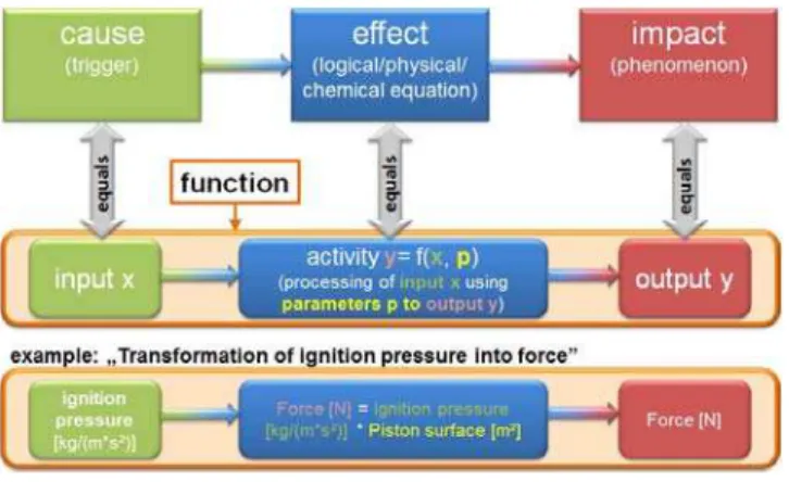
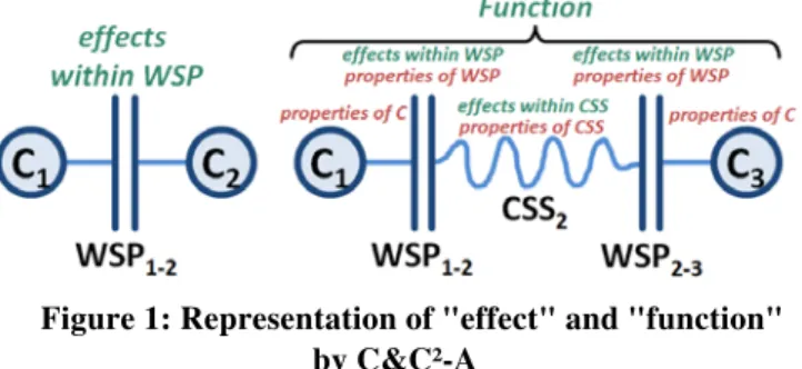
“The first hypothesis states, that every technical system fulfills its function by interacting with adjacent systems. Effects can only take place if a WS is in contact with a further WS and thus a WSP is built up.” [35] The second hypothesis defines, that “…Functions are represented by at least two WSP’s, the connecting CSS and at least two Connectors which embed the model into the environment. The properties of WPSs, CSSs, Connectors and the effects taking place in the WSPs and CSSs are determining for the fulfillment of the function.” [35] (cf. Figure 1).
Figure 1: Representation of "effect" and "function" by C&C²-A
The effects, which take place in every WSP, are caused by properties of the WSP (i.e.: surface shapes, friction, electric resistance between a material pair or data types). The transformation of the incoming object flows (matter, energy, force and information) to outgoing object flows in the CSS is characterized by properties of the CSS (i.e. geometrical shape, material stiffness, data processing) and appearing effects within CSS. Furthermore, relevant properties of the Connectors also influence a function, which comprises these effects and properties. Hence, these aspects define the characteristic of the function. That means, an output object flow value can be calculated for a given input object flow value using the information, which is defined and provided by the C&C²-A.
“The third hypothesis defines the adaptable (fractal) character of the approach according to the focus of observation. Thus every system and subsystem can be described by the basic elements WSP, CSS and Connector on different levels of abstraction and detail.” [35] This allows designers to increase or decrease the level of detail during analysis of design problems and synthesis of solutions for them.
ECKERT ET AL. [36] have investigated the application of the approach for functional analysis of an axial piston pump in a survey with several engineers. They aimed to identify the different notions of functions and pointed out, that the approach in fact helps to analyze products, but the procedure and the results are still too heterogeneous.
Before introducing this profile in detail, crucial terms will be defined and formalized in graphical representation in the following chapter.
V. TERM DEFINITIONS AND FORMALIZATION
In the previous chapter, the Contact & Channel – Approach has been introduced and the terms function and effect have been explained in their semantic context. These aspects will be addressed later in this chapter again.
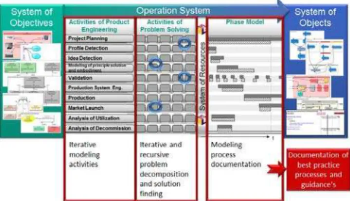
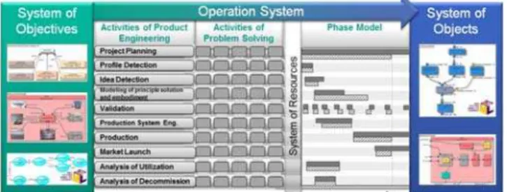
New product engineering or innovation processes start with the identification of the stakeholder’s needs and objectives. They are central elements and coevally very uncertainty-affected, which obstructs the definition of clear and durable requirements for engineers. The aspect of uncertainty is closer investigated by ALBERS ET AL. [40]. OERDING [41] conducted extensive assessments on the specifications of objectives using the Contact & Channel – Approach. He stated the hypothesis, that every product engineering process is unique and individual. Furthermore is stated, that this process can be described by the System of Operation, which constructs and completes the System of Objectives and develops the according System of Objects that comprises the resulting product and adjacent findings. Objects are described by the elements of C&C²-A and need to be validated in terms of fulfillment of the Objectives before becoming part of the System of Objects. All these aspects are described and represented in the Integrated Product Engineering Model (iPeM) [42], [43]. Figure 2 shows a representation of the System Triple as well as contained engineering activities, problem solving activities and the emerging phase model. The System of Objectives and the System of Objects are here illustrated by exemplified SysML Diagrams.
Figure 2: The Integrated Product Engineering Model (iPeM)
One important part of the presented approach at hand is the advancement and formalization of the specification of the System of Objectives and the integration into a SysML-Profile in form of according modeling entities and relations, including the findings and hypotheses from the previously introduced research works. Thus, the modeling language must be capable to describe and represent the traceability from partially vague stakeholder objectives via technical requirements and according functions right up to the system embodiment.
First of all, Use Cases are applied for modeling the purpose of the system under development or - in other words - the features the product shall provide. A feature describes in textual manner, what the entire product shall
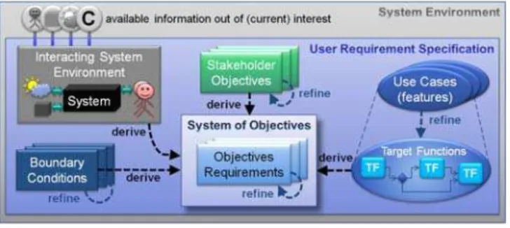
do, without stating any quantitative information. For a more clear description of the internal progress of Use Cases (features), or a qualitative description of the intended system behavior, Activity Diagrams are applied. These are capable to model logical procedures and decisions among others. Due to the fact, that activities will be used for modeling aspects of realized product functions as well, they are here called Target Functions and have a differing appearance in diagrams (light blue instead of green, see Figure 3).
Figure 3: Model elements and relations of User Requirement Specification
From the previously defined aspects, the first central hypothesis for the application of the presented modeling technique is derived:
This hypothesis assures the maximum possible solution space for an innovative technical solution for the system under development and a minimization of ambiguity. The system boundary comprises not only the external boundaries to adjacent socio-technical systems like the environment (i.e. climate, underground), technical neighbor systems (i.e. radio communication, data interfaces, mountings), interacting humans, but also internal boundaries like purchased subsystems or software, which have to be integrated. The system boundaries can only be modified in agreement with the stakeholders. Adjacent systems and their properties may never be manipulated, only system boundaries may be relocated (i.e. in order to access different interfaces). In contrast, no element of the User Requirement Specification shall affect any subsystem within the system under development. The URS is ideally completely defined at the beginning of a new product engineering process. The information from the URS and the derived initial System of Objectives are applied as starting point for the product engineering process.
When the first activities of the Operation System are performed (cf. Figure 2), the System Architecture will be developed. Coevally, further technical Requirements will be derived and added to the System of Objectives. The set of all technical requirements is often called Systems Requirement Specification (SRS) in product engineering. Hence, the SRS is part of the System of Objectives. For a better discriminability, technical requirements are also subdivided into several types with specific characteristics. In the modeling technique at hand, three types of technical requirements are defined: the Continuous-Function Requirement, the Statechange-Function Requirement and the Property Requirement. This distinction stems from the Functional Concept of Systems Theory according to ROPOHL [45], depicted in Figure 4.
Figure 4: Concepts of Systems Theory (translated from ROPOHL)
ROPOHL divides between three concepts of Systems Theory, the Functional Concept, the Structural Concept and the Hierarchical Concept. The aim of the presented modeling technique is to support a function-based modeling approach, but based on the understanding of “function” according to the C&C²-A, comprising, but not limited to the definition according to ROPOHL.
A system can take up several states, which is analog to the Functional Concept. Within a certain state, the system can perform continuous functions (i.e. transmit torque, record temperature, process audio data). When the system changes its state, this is usually triggered from outside the system (i.e. a user) or by a function (i.e. gear shift command from automatic transmission control unit). When performing this state change, the system again performs functions, but in this case, these functions are discrete with a dedicated initial state and a dedicated final state (i.e. shift from gear 1 to 2, load application, start engine). These two types of functions need to be distinguished, which is also realized in SysML by default through activities within state transitions and so-called “do:activities” within states. How this concept is applied for functional modeling is elucidated later. In the current context, this distinction is important in terms of clear requirement specification, hence the two types Continuous-Function Requirement and Statechange-Continuous-Function Requirement are defined for this purpose. The third type (Property Requirement) is by itself a non-functional requirement and defines properties of WSP or CSS. Nevertheless, these properties are responsible for effects, which again influence the characteristic of a function. H1: The User Requirement Specification (URS)
From the three types of technical requirements and their application results the second hypothesis of the modeling technique:
The most important statement of this hypothesis is that all defined and technically relevant aspects of the URS have to be translated into technical requirements. This means for the modeling practice, that System Engineers can for instance reproduce the traceability from Stakeholder Objectives or Boundary Conditions to Technical Requirements and furthermore verify the fulfillment of all objectives.
In real product engineering processes, usually not all elements of the URS are completely defined and not all properties of adjacent systems are explicitly excluded or included from the beginning. This accounts on the state of knowledge and the state of definition. ALBERS ET AL. [46] propose the Advanced System Triple Approach, which describes this co-evolutionary and iterative process of synthesis and analysis including the human-based, knowledge-based and process-based aspects and supports the understanding of handling Systems of Objectives in complex and uncertainty-affected product development.
After having formalized the entities and relationships for modeling all user requirements and the System of Objectives, the according modeling artifacts for the System of Objects are defined and formalized. The technique for modeling the System Architecture is function-based and applies the concepts of C&C²-A. According to ALINK [34] and ECKERT ET AL. [36], the term “function” is interpreted in many different manners. Their assessments figured out, that the 5-key-concept of VERMAAS [47] is the most promising definition to bring these different viewpoints together (see Figure 5).
Figure 5: 5-key-concept of VERMAAS [47]
This definition is divided into two main sections, the intentional description and the physical/chemical description. The former section is fully covered by the elements of the System of Objectives. So are goals of the device equaling the Stakeholder Objectives, actions with the device and environment-centric functions of the device are
described by Use Cases (the features of the product) and their internal progress, which is realized by the Target Functions in SysML. For a better discriminability, the standard-activities are green; Target Functions appear in light blue color (similar to Use Cases).
The physical/chemical description of functions concerns those functions, which are part of the System of Objects, respective the realized System Architecture. The device-centric functions of the device in the 5-key-concept are defined using the C&C²-A. Functions by itself are a solution-neutral description of what a system (or subsystem) does. But due to that a function according to C&C²-A can only be fulfilled by an embodiment, certain information about technical principles are inherently applied. This means, when a required product feature is realized by development of a System Architecture, it has to transform the given inputs at the affected Connectors to the system environment into the demanded outputs at the according Connectors towards the system environment. Connectors itself would also be CSS whether they were completely part of the system under development. But when these CSS are located outside the system boundary, not all information of them is relevant for the currently regarded function. Hence, these “virtual” CSS are called differently (namely Connector) and contain only the function-influencing information share of the CSS. ALINK [34] defines, that Connectors are always a reduced model of the system environment, which contains only that share of information, which is relevant for the analyzed function at hand.
The development of a System Architecture is done by decomposition of functions into sub-functions, which step by step fulfill all demanded aspects. This decomposition is an engineering activity, which applies suitable technical principles. An example: the main Use Case (feature) is “transformation of chemical energy into electrical energy” (in fact the purpose of a generator). When decomposing it, the chemical energy is firstly transformed into pressure (by combustion). Then, this pressure is transformed into a guided force (i.e. by a piston in a cylinder liner). The force is transformed into a torque (by a crankshaft), which is finally transformed into electrical energy by a dynamo. The restrictions and coevally the starting point of possible solutions are the given Input Object Flows, starting with these at the system boundary, which are specified by the Connectors. From the functional decomposition, the resulting system behavior (or behavior of the device in the 5-key-concept) can be derived. A behavior sets functions into a logical sequence, depending on the Object Flows, again starting at the Connectors at the system boundary. A behavior is the resulting, perceptible interaction of a system with its environment. Furthermore, a behavior depends on the structure and the properties of a device (combined named as embodiment). They quantify how a function is performed and makes functions and behavior calculable. HOOVER ET AL. [48] state, that finding the bounds of design parameters is often useful during the design process, they can be applied for verification of designs and as a basis for further, derived requirements. Moreover they state that each behavior can be analyzed independently, but the behaviors interact through the embodiment parameters. In fact, this H2: The System Requirement Specification (SRS) as
means that design parameters or in other words the embodiment is responsible for the quality of function fulfillment. Figure 6 visualizes a formal definition of the term Function by showing all participating aspects and relations (colored).
Figure 6: Formalization of the term "Function" in terms of C&C²-A
The main elements in this figure are the Object Flows and their transformations (green) and the applied WSP’s and CSS’s. More in detail, the Input Object Flow from Neighbor A (specified by Connector CA) enters the system at WSPA-N. Then it is transformed within an Activity (performed by CSSN). Finally, it leaves the system at WSP N-B as Output Object Flow towards the neighbor system B (specified by Connector CB). The effects appearing in WSPA-N, CSSN and WSPN-B are affected by Property Parameters (in the figure shortly: Properties). The CSSN is contained in the system embodiment N, which may also contain other CSS’s. All elements belonging to the embodiment are colored in red within Figure 6.
An example may help to explain the meaning of Channel and Support Structures. CSS’s only comprise the structure share of an embodiment, which participates in a function. For instance the transmission of a certain force from one WSP to another would only be conducted by that structure share, which in fact carries that force. The structure of an embodiment, which does not carry any force, is called Remaining Structure (RS) [32]. When one embodiment carries multiple forces between different WSP’s, i.e. in different states or loading cases, it would consist of multiple CSS’s. This is why a CSS is contained in an embodiment, but an embodiment is usually not equivalent to a CSS.
Coming back to the term “function”, there are some more important terms to define in order to improve its understanding. An Input Object Flow is transferred to an Output Object Flow. This is easily comprehensible for software engineers, but what about mechanical engineers, for whom the modeling technique at hand is in particular made for? Figure 7 attempts to set typical terms for the description of systems into a semantic context of a function.
Figure 7: Semantic context of "Function"
An important engineering activity for the analysis of technical systems is validation [49]. When validating a system, resulting effects at defined WSP’s from appearing phenomena within a concrete system behavior are analyzed and balanced with the requirements in the System of Objectives [50]. These phenomena are the outputs of functions, which are caused (by triggers or excitations) through input object flows at the according WPS’s within the assessed system behavior. This so-called event-chain is exemplified in Figure 7 and Figure 8 for the transformation of ignition pressure into force.
Figure 8: C&C²-A analysis of piston function
Concluding, hypothesis 3 states following semantic relationships for the formal, function-based description of technical systems:
As already stated before, the system behavior is the resulting, perceptible interaction of a system with its environment. In other words, the behavior is the reaction of the System Architecture onto caused functions by triggers or excitations. This fact implies a time dependency and measureable causes for a quantifiable manner of function performance to make a behavior observable. Moreover, different excitations or triggers cause different functions or deviating output quantities and hence a differing system behavior. This awareness is crucial for the validation activity: enabling an engineer to validate a system regarding expected behavior under all possible conditions requires testing all possible variations. This is why the modeling methodology also comprises Test Cases, which describe a concrete instance of a Use Case. When regarding Continuous Functions, excitations or triggers are continuous Input Object Flows (i.e. incoming torque or electrical energy). In contrast, Statechange Functions have discrete triggers, the Events (i.e. pressed start button, time limit reached). The according diagram to represent the progress of a Test Case is the Sequence Diagram. In combination with the System Architecture (modeled in activity diagrams, state diagrams and block diagrams), it complements the specification of a system behavior.
Hypothesis 4 concludes the semantic relationship of function, behavior and Test Case in terms of the modeling technique at hand:
The system embodiment, realized and modeled in logical or physical structures, performs functions within states or transitions. This becomes perceptible and measureable through Test Cases, which validate the resulting system behavior. These statements again correlate with the 5-key-concept of VERMAAS [47].
The previously formalized terms and their semantic definitions build the basis for a common language to facilitate tool-supported modeling of technical systems. The
implementation of this language is done by a SysML-Profile, which yet complies most of these aspects and which will be introduced in the following chapter. However, further advancements are still necessary to create even more clear and comprehensible representations due to tool-dependent restrictions. For instance, the sequence diagram traces from software modeling, just as the model entity “event” also does. An absolutely consistent representation and specification of system behavior for non-software systems is not as yet obtained and still part of research. This is why the next chapter drops this aspect, but introduces the important extracts from the meta-model for representing the other formalized aspects presented before.
VI. ENHANCEMENT PROFILE FOR THE SYSTEMS MODELING LANGUAGE (SYSML)
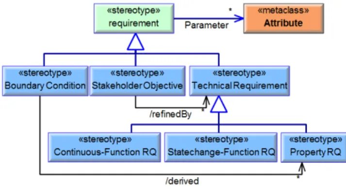
SysML applies the OMG Standard Meta-Object Facility (MOF) [51], which facilitates compatibility of the modeling language to manifold other standards, as already introduced in chapter III. Hence, this standard is also applied here. The basis for the extending SysML-Profile, which is introduced in this chapter, was set by ALBERS and ZINGEL [37] by the integration of basic entities of C&C²-A into SysML. Within the past year, the profile was extended by the elements for enabling more differentiated modeling of the System of Objectives through different Requirement Types as introduced in the first part of the previous chapter. An extract of the according meta-model is depicted in Figure 9. All extensions are visualized through blue color.
Figure 9: Extract from the meta-model-extensions for requirements
From the common SysML-requirement, three specialized sub-types are implemented: The Boundary Condition, the Stakeholder Objective and the Technical Requirement. These elements inherit the properties of the common Requirement and add new properties. A second level subdivides the Technical Requirement into the Continuous Functions Requirement, the Statechange-Function Requirement and the Property Requirement. All Requirement Types can apply one or more parameters with according Value Types for measureable specification of required system properties (i.e. costs, weight, size) or phenomena, which require certain Output Object Flows of Functions (i.e. fuel consumption, noise, response time). Two important relationship types (reference tags) are also depicted: Boundary Conditions can derive Technical Property Requirements towards WSP’s at the System Boundary (i.e. Interface data types, flange geometries, H4: The system behavior is the perceptible and
measureable reaction of the System Architecture (functions, states, and embodiment) on continuously or discretely caused functions. Discrete function triggers are Events, Continuous function excitations are continuous Input Object Flows. System behavior can be validated through the application of Test Cases, which are instances of Use Cases.
installation space), which will interact with existing, adjacent systems. Technical Requirements refine Stakeholder Objectives (i.e. “pure electrical driving” towards “E-Motor must have at least x kW”), defined in the engineering activity (cf. Figure 2) of modeling principle solutions and embodiment design (what the mentioned E-Motor is part of).
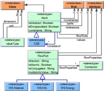
Beside the extension of the SysML towards traceable modeling of the user requirements and the System of Objectives, the metamodel is also applied and extended towards function-based modeling according to C&C²-A. For this purpose, the affected entities and relations are extended (see Figure 10). The stereotype Function extends the metaclass Activity and is specialized by Target Functions (describing the desired process of a Use Case), Continuous Functions and Statechange Functions. The according causes and performing entities (States respective Transitions) are also depicted. A Function is performed by a block, which again can consist of multiple CSS’s. This stereotype again has attributes like values (which are in fact Parameters) and Flow Ports (which can transport Object Flows. The extended entities and relations are visualized in blue color within Figure 10.
Figure 10: Extract from the function-related meta-model-extensions
Activity Groups can be allocated to Blocks or directly to CSS’s. One block should consist of at least one CSS, but may also contain multiple of them due to the principle of C&C²-A, that one embodiment can perform multiple Functions (see Figure 11). Blocks in SysML can have Flow Ports, which are interfaces that can transport Object Flows. The assignment of Object Flows to Flow Ports is also done by the allocation-relationship (not depicted in Figure 11). When having done such an allocation, this equals the meaning of Working Surfaces, wherefore the Stereotype Flow Port is extended by three types of WS (Material, Energy and Info). Connecting two Flow Ports establishes a potential WSP, which becomes a real WSP in case of allocating according Object Flows as explained before. Otherwise, two connected Flow Ports represent only possible WSP’s, due to that they are actually not part of a Function. Furthermore, Blocks can gain values, which equal to Property Parameters.
Figure 11: Extract from the embodiment meta-model-extensions
There are several more aspects contained in the SysML Metamodel [52], which are also applied within the modeling technique at hand. State Diagrams are used to specify system States and to allocate Continuous Functions to States and Statechange Functions to Transitions, as depicted schematically in Figure 12.
Figure 12: System States, State Transitions and according Functions
State Transitions are triggered by Events (red), the causes to initiate the performance of Statechange Functions (i.e. “Shift from 1st into 2nd gear”, violet in Figure 12). Guard Conditions (green) can optionally be added to assure, that Transitions are only accomplished under certain conditions (i.e. “HV battery SOC > 90 %”). During this Transition, the system conducts a specific behavior, depending on the concrete Object Flows. Part of this behavior can be the creation of new possible WPS’s, which may be applied for the performance of Continuous Functions (violet in grey boxes in Figure 12) within the now applied State. Hence, Continuous Functions are performed within a system State by using the established Working Surface Pairs. The latter aspect of establishing new WSP and disconnecting WSP is currently not integrated and represented in SysML, because of the limitation, that geometrical information yet cannot be adequately represented in diagrams. However this is aimed to be realized in the near future.
VII. INTEGRATED MODELING TECHNIQUE
As mentioned at the beginning of chapter V, every product engineering process is unique and individual. Therefore, this chapter cannot provide one commonly applicable general modeling guidance for all kind of engineering processes. However, it assigns engineering activities of the Integrated Product Engineering Model (iPeM) to according modeling activities. Each activity runs through problem solving processes, partially in iterations or recursively (see Figure 13).
Figure 13: Representation of modeling activities and applied process in the iPeM
The resulting modeling process can be captured and documented by an application model of the iPeM (for more information about application models see [42]) and serves as “best practice guidance” or starting point for following product engineering processes. The iPeM itself can yet not be modeled within SysML in satisfying manner, but ALBERS AND BRAUN [44] are currently developing methods including prototypic tool support for modeling all process-relevant information. The advancement towards integration of product-relevant information into the process model is part of current research.
Before starting to model products, a crucial activity is to be conducted: identification of the model purpose(s). The amount of efforts spending for modeling systems must be balanced with the benefit of improving communication and collaboration as well as knowledge documentation and representation. In most cases, not all aspects of SysML are required for obtaining benefits from the model-based approach, especially in case of smaller companies and/or projects.
The first frequently beneficial modeling activity is the specification of the User Requirement Specification before starting the product development itself. For this purpose, the relevant share of the system environment, Use Cases, Stakeholder Objectives and Boundary Conditions are captured. During the activities of project planning and profile detection, the initial System of Objectives is derived from the URS using primarily Technical Requirements. The activities of profile detection and idea detection identify first candidate System Architectures, which can be specified in the system model. From here on, the C&C²-A acts as creativity-supporting pre-thinking tool (see chapter IV). Within the activity of modeling principle solutions and embodiment design, the modeling language is most extensively used and crucial for communication and
collaboration of involved engineers and managers, i.e. by supporting them in substantiation of important decisions. Functions are determined or derived from Use Cases and their progress models and according system states are defined. This information is used as basis to design the performing embodiments with according properties. Both aspects (functions and embodiment) are cross-linked (or allocated) to each other in order to establish a combined view on the system architecture. Emerging Technical Requirements are now iteratively and recursively derived in order to sharpen the System of Objectives towards finding satisfying embodiments as part of the System of Objects.
As stated in chapter V, validation is substantial for product engineering. Therefore, the focus in modeling during this activity is set on networking the elements within the System of Objects to the according requirements within the System of Objectives. Furthermore, Test Cases are specified as validation sequence documentations. These Test Cases are also linked to requirements, whose satisfaction is to be verified. Figure 14 gives an overview of all modeling activities, contained in the modeling technique.
Figure 14: Overview of modeling activities
Within the last years, several Systems Engineering methodologies have been developed and published (i.e. the Object Oriented Systems Engineering Method (OOSEM) [53] or the Systems Modeling Process (SysMOD) [54]), which are also compatible with the presented technique. For more information, refer to ESTEFAN [55], who conducted a survey of the most popular SE-methodologies.
The next chapter introduces some aspects of an application example of the presented system modeling technique and points out, how the resulting model was integrated into the engineering environment.
VIII. APPLICATION EXAMPLE:HYBRID POWERTRAIN The aim of applying a hybrid powertrain as a complex mechatronic system was to verify and advance the presented integrated modeling technique, including the abstract and concrete syntax of the modeling language, its provided views and the modeling methodology.
using the “extend” relationship. A further decomposition by Target Functions has been omitted in this application example, due to that this aspect has not yet been implemented in the herein applied profile extension. (The reason is that this improvement is the newest one in the profile.)
Figure 15: System Use Cases respective features
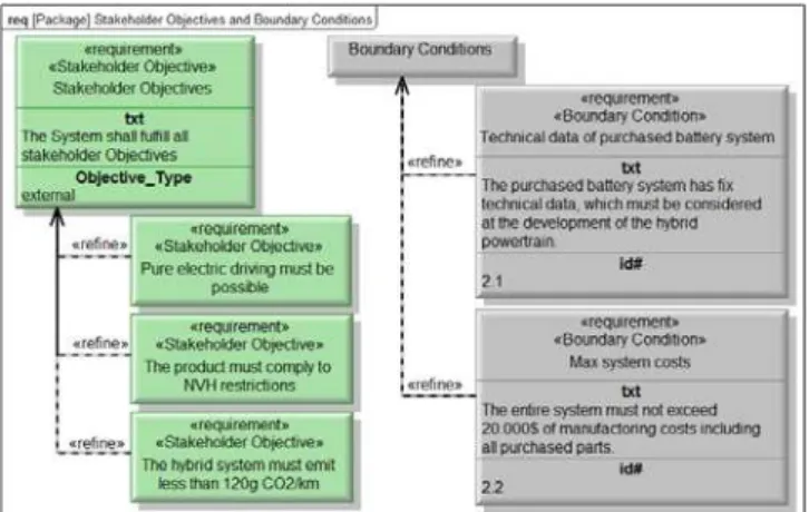
The yellow entity is a Test Case, which will be specified further later. Figure 16 shows some fictive Stakeholder Objectives (green) and Boundary Conditions (grey) for the hybrid powertrain system. Additionally, the information about the objective type from the company’s point of view (external or internal) is depicted.
Figure 16: Stakeholder Objectives and Boundary Conditions
During the engineering activities, these common, superior requirements are translated (derived) into technical requirements, as shown in Figure 17.
Figure 17: Technical Requirements
The different colors help to distinguish between the different types of requirements. Modeling requirements in SysML is beneficial for networking them with according model artifacts of the System Architecture. Thus, existing requirements can within most commercial tools be imported
from Requirement Management Tools like DOORS or MKS, which spares additional effort in copying them by hand. Some tools also provide bidirectional synchronization interfaces. For more information towards integrated requirements modeling, refer to MALETZ [56].
Coevally to modeling requirements, the system environment, respective connectors to adjacent interacting systems can be modeled in order to derive additional Technical Requirements or Boundary Conditions. Figure 18 represents the system environment of the hybrid powertrain.
Figure 18: System environment
The implemented images enable an easier understanding by non-professionals in terms of modeling. The symbols between the depicted systems are possible Working Surfaces, whereof the red color stands for energy-transmitting interfaces, blue for material and yellow for information. The WS are called “possible WS”, because they do not yet participate at any function, but they may be applied later. However, these interfaces already obtained names and information about the type of transmittable Object Flows across the system boundaries in order to specify the interaction channels of the system under development with its adjacent systems. Hence, these WS have to be designed by systems engineers and constructors by pre-thinking their future functional purpose.
The entire product features, represented as Use Cases, can already be decomposed using Activity Diagrams. These Target Functions are initially transferred into Functions of the System Architecture and then further decomposed.
In general, SysML can be integrated into any tool environment using application programming interfaces, provided by most of the available modeling tools. These interfaces use the Extensible Markup Language (XML) [57] for data exchange. The ISO 10303, also known as the STEP family [58], contains several application protocols, which specify the transmitted information for certain purposes or disciplines. One of them is AP233, the application protocol for Systems Engineering data representations.
capability of the SysML-extension to realize such integration at the example of Simulink. For this purpose, some sub-systems of the hybrid powertrain were further detailed in a separate, synchronized model using internal block diagrams. The modeled information also resulted from application of the function-based approach, which was presented in the previous chapters.
Before demonstrating the model synchronization, some shares of the modeled hybrid powertrain System Architecture is introduced. The provided information basis in the previously introduced System of Objectives is starting point for identifying function-based technical solutions for the demanded features, before designing the function-fulfilling embodiment. Functional models have the purpose to depict the transformation of Input Object Flows by Activities into Output Object Flows. Commonly, this transformation is not a linear sequence, but rather decision-driven. This is why the applied Activity Diagrams provide decision-, fork-, join- and merge-nodes for modeling the logical progress of functions.
A simple example for a function-based representation of the actuation of the accelerator pedal is depicted in Figure 19.
Figure 19: Function-based model of accelerator pedal actuation
The blue entities stand for Functions, which are networked to a logical order using control flows (the dashed lines). Additionally, the small yellow and blue boxes represent PIN’s, which are connected by Object Flows. These artifacts represent the flow of information (yellow) and energy/force (red). In this diagram, also the Events, which cause (trigger) the depicted function, are represented at the upper end in dark blue color. The entire information in this diagram describes the function “actuate accelerator pedal”, which is yet not performed by any embodiment. The distinction between Continuous Functions and Statechange-Functions is done by assigning the Stereotypes “continuous” or “discrete” to Object Flows, as exemplarily shown for the information flow “Position” in Figure 19.
Functions can be iteratively or recursively decomposed by creating new diagrams on activities and modeling the logical progress of a function in more detail. Very complex
functions can also be represented in multiple diagrams on the same level of detail for more clearness. These possibilities to switch between different levels of abstraction and to depict different views for different stakeholders contribute to the application of the fractal character of C&C²-A.
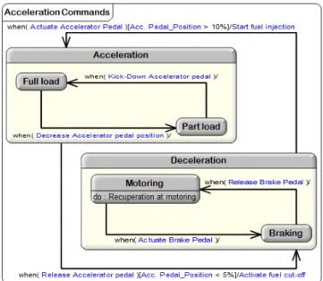
Beside the representation of the logical progress and the Object Flows within functions (for more information refer to [54]), the according system States need to be modeled. The purpose is to represent which functions are performed in or between which states and under which preconditions. This is done within State Diagrams. Here is modeled, when States are changed under which conditions and which functions are performed within certain States (the Continuous Functions) or during Transitions (Statechange Functions). Figure 20 shows a simplified State Diagram with two main States “Acceleration” and “Deceleration”.
Figure 20: State Diagram with Acceleration States
Within both States, sub-States are embedded, which refine the main States. The blue elements within the round brackets are linked Events, which trigger the transitions. The elements in the square brackets are guard conditions (here: the Parameter “Acc. Pedal Position”, which has to exceed 10% when switching from Deceleration to Acceleration). The elements after the slash are Statechange Functions (i.e. “Start fuel injection”). In the Sub-State “Motoring”, an example for a Continuous Function is represented. This Diagram applies to the representation in Figure 12. These two diagram types (Activity Diagram and State Diagram) are capable to model comprehensive information about system functions. Moreover, these aspects will be applied for the definition of Test Cases later on.
participate at the energy transmission from the fuel tank or the HV battery towards the wheels on the road.
Figure 21: Hybrid Powertrain embodiment
The applied Internal Block Diagrams directly show instantiated Blocks instead of CSS, due to that they are contained in the Blocks (more information about the underlying Class-Instance-Principle of UML/SysML can be found here: [7], [54]). The different colors help to distinguish more easily between the main functional purposes of the components. For instance, all blue components are energy storages, the grey components are part of the conventional powertrain and the red elements are part of the electrical powertrain. However, this distinction is only made for representation purposes and has no meaning for the deposited powertrain model. Figure 22 shows the same system detail level, but from another viewpoint. Some components appear again (i.e. ICE, transmission), but the majority is now shielded, although other components appear. This view emphasizes on sensor systems and their connections within the system compound.
Figure 22: Extract from applied sensor systems
Among others, the “Accelerator pedal position sensor” appears which is intended to perform the function “Measure Acc. Pedal Position” from Figure 19. When all necessary components for performing certain functions are developed, components and functions can be cross-linked (see chapter VI). An example for this integrated view is depicted for the function “Actuate Accelerator Pedal” in Figure 23.
Figure 23: System Architecture of accelerator pedal actuation
This representation shows the integration of functions and structure and is hence the System Architecture of the subsystem that is responsible for the actuation of the accelerator pedal. Coevally, this diagram needs to be further advanced towards more detailed integration of the function-based information and the performing embodiments. For instance, Object Flows (solid arrows) have an equivalent meaning like Item Flows in Internal Block Diagrams. It would be desirable to allocate the effectively conducted Object Flows during performance of a certain function directly into the applied Connectors. The same applies to PIN’s and Flow Ports. This is principally already possible by using the Allocate-Relationship of SysML. Unfortunately, there is no integrated visualization of Object Flows using connectors provided in SysML. This advancement is important for the full integration of C&C²-A in SysML, where an engineer should be able to see, which Objects flow via which CSS’s and WSP’s. There will be some more information on that issue in the outlook at the end of this article (chapter X).
Figure 24: Traceability between System of Objectives and System of Objects
Here, the HV Battery is a purchased part, which entails the exemplified Boundary Condition “Technical data of purchased battery system” that contains several refining Technical Requirements (not shown in the diagram). Blocks, which are in fact embodiments (components), can only satisfy Property Requirements, Continuous Functions may only satisfy Continuous Function Requirements and Statechange Functions may only satisfy the according Statechange Function Requirements. Restricting the modeling language in this way aids to avoid incorrect networking of elements.
All this information can easily be represented and exported into requirement tables or matrices, what is very beneficial for requirement engineers, but also for development engineers. The traceability between the System of Objectives and the System of Objects contains another aspect beside requirement fulfillment: the definition of Test Cases.
As stated before (see chapter V), validation is a crucial product development activity. For this purpose, the second aspect of cross-linking between the two Systems (Objectives and Objects) is done by modeling Test Cases for certain Use Cases in order to provide a validation specification. This is done within Sequence Diagrams, which complement the System Architecture by defining concrete Events for specific usage sequences respective Test Cases. As shown in Figure 15, the Use Case “Recuperation at Motoring” was declared as Test Case (yellow element in the diagram). Now having the information about the developed System Architecture, concrete functions for embodiments can be predefined by events in order to verify the intended behavior. Thus, the functions are now caused by the definition of certain trigger (or excite) Events and specific parameters are predefined by the Property Parameters of embodiments. This leads to a measureable behavior, because the resulting object flows can now for instance be calculated or simulated. Figure 25 shows a very simplified example Test Case sequence.
Figure 25: Sequence Diagram for a Test Case
On the left side, the sequence progress is defined (i.e. by sequential steps, iterations or parallel steps). The blue colored names represent the performed functions, which have been dragged and dropped from the modeled System Architecture. The red elements at the upper side are the affected embodiments (components). Moreover, adjacent interacting systems (Actors like the driver in this example) are integrated. The arrows represent the triggered Events, or in other words, the caused functions in this test sequence. As stated before, this representation is just a preliminary solution due to several inconsistencies, tracing from the original purpose of Sequence Diagrams to only model software systems (they are in fact just adopted UML-diagrams).
The following chapter introduces an example for the synchronization of the SysML-model with Simulink in order to facilitate executable simulations of the powertrain behavior.
IX. INTEGRATION OF SYSML AND SIMULINK FOR A HYBRID POWERTRAIN SYSTEM
SysML itself is not executable. However the compound of behavioral diagrams (Activity Diagram, State Diagram and Sequence Diagram) is capable to specify a formal and thus executable set of information, due to that they have been directly adopted from UML. Though, the effort of modeling technical systems on a high level of abstraction is contradictory to a formal code-conform modeling approach. Much easier is the integration of an interface to Multi-Body-Simulation Tools, which are synchronized with Internal Block Diagrams. The information from the SysML-model serves as framework including “functional blocks” and interfaces in Simulink, which have to be completed within the MBS-tool for enabling simulation of the model. Several tool vendors already provide such interfaces, i.e. towards Simulink. This interface has also been applied within a student project work for a modification of the presented hybrid powertrain.
Firstly, Internal Block Diagrams (IBD) as part of the system architecture of a hybrid powertrain were modeled in SysML, using the extending profile of the modeling technique at hand (see Figure 26).
Figure 26: Top-Level Internal Block Diagram of a hybrid powertrain
of the applied SysML-modeling tool. Figure 27 shows the synchronization result in Simulink.
Figure 27: Synchronized Top-Level diagram of the according Simulink-Model
In addition to the provided information from the SysML-model, physical elements are added in Simulink in order to enable a “real” transformation of Object Flows from inputs to outputs. Afterwards, real Test Cycles can be defined in Simulink. For this purpose, concrete Input Object Flows are set, in the given example, this was done for “throttle”, “brake”, “boost” and “shift”. Their progresses and the according simulation outputs are depicted in Figure 28.
Figure 28: Simulation results of hybrid powertrain
The synchronization interface itself was not modified here. The focus was set on testing the feasibility of application of such a tool interface within the presented modeling technique and on relevant information to synchronize.
X. CONCLUSION AND OUTLOOK ON FURTHER RESEARCHES
This article introduced the advancements of an integrated modeling technique, which was initially presented by Albers and Zingel [37] and Albers et al. [38] in 2011. During the last year, the heterogeneous term understanding was a ubiquitous challenge, wherefore important terms have been formalized and set into semantic relationships. Four main hypotheses have been derived from these findings. The efforts on improving this common discipline-crossing language are currently continued, among others through evaluating term understandings in research and industry by an online-survey or by observing and supervising further pilot projects in industry.
The functional modeling approach will be advanced through combination with LAMM’s and WEILKIENS’ “FAS-Method” (Functional Architectures for Systems) [59], [60], which is capable to automate several modeling steps and to
support engineers by integrating a new, function-based block diagram view. This method also applies matrices to visualize the relationships between activities and functional blocks. The aims for the future are further advancements towards easier application of discipline-crossing system model for mechanical engineers and managers, i.e. by integration of new views like the matrices from the DSM/MDM-approach (see [15]) or more geometry-related representations. Especially the issue to represent the information about the system functions and the performing embodiment design with according property parameters like geometrical location and shape of WSP more adequately is still part of current research. The aim is to enhance the current SysML diagrams by some kind of “Embodiment Diagram” in order to improve its comprehensibility and applicability by mechanical engineers. Currently, a compact interface to CAD-software systems is under development at IPEK-Institute of Product Engineering, based on an extract of information transmitted via STEP-files. The aim is to reduce the information amount by only exchanging crucial instead of comprehensive information. The resulting information is intended to establish the previously drawn Embodiment Diagram as an abstraction of 3D-CAD models.
Furthermore, the presented function-based modeling approach according to C&C²-A is capable to serve as a modular, function-based product portfolio management technique. The K2-funded research project “Functional Management of Mechatronic Products”, which is conducted by the Virtual Vehicle in Graz in collaboration with the IPEK, the AVL List GmbH, the Chair of Product Development from the Technical University of Munich and BMW AG, focusses on development and advancement of such a function-based portfolio management technique [61].
The software-supported integration of product- and process-modeling is also part of current research at the IPEK. The aim is a combination of the strengths of both modeling techniques and the integration into a comprehensive development framework. The results from the advancements of the common language and the functional modeling approach will also be integrated there in order to provide a tool-supported, discipline-crossing development and management environment. Part of this tool environment will also be the derivation of further views on the emerging models, which are easier comprehensible by managers. The extracted information in such views can for instance be applied as basis for strategic decisions, supplemented by analyses like estimated costs, reliability or sustainability.
Concluding, the modeling technique is continuously advancing towards a fundamental support for engineers and managers of all disciplines in communication and collaboration over the entire product engineering process. First applications of the current modeling technique in pilot projects proved benefits in overcoming traditional document-based approaches by improving consistency, clearness, completeness and sustainability through Model-Based Systems Engineering approaches.
XI. ACKNOWLEDGEMENTS
This research work is done in close cooperation with several colleagues at the IPEK – Institute of Product Engineering, who significantly contributed to the presented findings. In particular, the authors thank to Andreas Braun, Björn Ebel, Quentin Lohmeyer and Eike Sadowski for their fruitful feedbacks and constructive inputs. Moreover, the authors appreciate the contributions of Kurt Kruppok for his assessments towards coupling SysML and Simulink, which was presented in chapter IX. Finally, the authors gratefully acknowledge the close and valuable collaboration of all involved colleagues from AVL List GmbH in Graz, who contributed their share to the application example of the hybrid powertrain.
REFERENCES
[1] Bae, Y.-K.; Bénitez-Silva, H.: The Effects of Automobiles Recalls on the Severity of Accidents. Department of Economics Working Paper, New York, USA, 2010.
[2] Gallaher, M. P.; O’Connor, A. C.; Dettbarn, J. L.; Gilday, L. T.: Cost Analysis of Inadequate Interoperability in the U. S. Capital Facilities Industry. NIST, U.S. department of Commerce, Galthersburg, Maryland, 2004.
[3] Barber, P.; Graves, A.; Hall, M.; Sheath, D.; Tomkins, C.: Quality failure costs in civil engineering projects. In: International Journal of Quality & Reliability Management, Vol. 17, issue 4. Emerald Publishing, UK, 2000.
[4] International Council on Systems Engineering (INCOSE) Homepage,
http://www.incose.org, 2012.
[5] International Council on Systems Engineering (INCOSE): Systems Engineering Vision 2020, Version 2.0.3, TP-2004-004-02, September, 2007.
[6] Specification: OMG Systems Modeling Language (OMG SysML™), Version 1.2. http://www.sysml.org, 2010 (publisher: Object Management Group).
[7] Friedenthal, S. et al.: A Practical Guide to SysML – The Systems Modeling Language. 2008 (publisher: Morgan Kaufmann, Waltham, Massachusetts).
[8] Karban, R.; Hauber, R.; Weilkiens, T.: MBSE in Telescope Modeling. In: INCOSE INSIGHT, Vol. 12, Issue 4, 2009.
[9] Stark, R.: Challenges in Modern Product Creation Processes - PEP2015. Presentation on ProSTEP iViP event “Systems Engineering”, Darmstadt, Germany, 15th December, 2011.
[10] Stachowiak, H.: Allgemeine Modelltheorie. Springer, Vienna, 1973. [11] Yoshikawa, H.: General Design Theory and a CAD system, In:
Man-Machine Communication in CAD/CAM, Sata, T. and Warman, E. (eds.), pp. 35–58, North-Holland, Amsterdam, 1981.
[12] Kikuchi, M; Nagasaka, I.: On the three Axioms of General Design Theory. In: Proceedings of the Int. Workshop of Emergent Synthesis 02. Kobe, Japan, 2002.
[13] Hitchins, D. K.: Systems Engineering: A 21st Century Systems Methodology. John Wiley & Sons, 2007. Chichester, West Sussex, England.
[14] Suh, N.P.: On functional periodicity as the basis for longterm stability of engineered and natural systems and its relationship to physical laws. Research in Engineering Design, Volume 15, Number 1. Springer, London, 2004.
[15] Lindemann, U.; Maurer, M.; Braun, T.: Structural Complexity Management: An Approach for the Field of Product Design. Springer, Berlin, 2009.
[16] Stark, R.; Beier, G.; Wöhler, T.; Figge, A.: Cross-domain dependency modelling - how to achieve consistent system models with tool support. In: Proceedings of the 7th European Systems Engineering Conference (EuSEC), Stockholm, Sweden, 2010.
[17] Dori, D.: Object-Process Methodology - A Holistic Systems Paradigm. Springer, New York, 2002.
[18] Sharon, A.; de Weck, O. L.; Dori, D.: Project Management vs. Systems Engineering Management: A Practitioners’ View on Integrating the Project and Product Domains. In: Systems Engineering Journal, Vol. 14, Iss. 4, pp. 427-440. Pub: Wiley, USA, 2011. [19] Engell, S.; Lunze, J.; Otter, M.; Mosterman, P.J.; Schmidt, G.;
Schnieder, E.; Frehse, G.; Buss, M.; Raisch, R.; Pereira Remelhe, M. A.: Modeling, Analysis and Design of Hybrid Systems. In: Lecture Notes in Control and Information Sciences, Springer, Berlin, 2002. [20] Schamai, W.; Fritzson, P.; Paredis, C.; Pop, A.: Towards Unified
System Modeling and Simulation with ModelicaML: Modeling of Executable Behavior Using Graphical Notations. In: Proceedings 7th Modelica Conference, September 20-22, Como, Italy, 2009.
[21] Angermann, A.; Beuschel, M.; Rau, M.; Wohlfarth, U.: Matlab - Simulink - Stateflow: Grundlagen, Toolboxen, Beispiele. 7. Issue, Oldenbourg Wissenschaftsverlag, Munich, 2011.
[22] Albers, A.; Matthiesen, S.; Thau, S.; Alink, A.: Support of Design Engineering Activity through C&CM – Temporal Decomposition of Design Problems. In: Proceedings of the Tools and Methods for Competitive Engineering (TMCE). Izmir, Turkey, 2008.
[23] Matthiesen, S.: Seven Years of Product Development in Industry – Experiences and Requirements for Supporting Engineering Design with ‘thinking tools’. In: Proceedings of the International Conference on Engineering Design (ICED), August 15-18, Copenhagen, Denmark, 2011.
[24] Andrianarison, E.; Piques, J.-D.: SysML for embedded automotive Systems: a practical approach. In: Proceedings of the Embedded Real Time Software and Systems Conference (ERTS² 2010), Toulouse, France, 2010.
[25] Shah, A.A. et al: Multi-view Modeling to Support Embedded Systems Engineering in SysML. In: Lecture Notes in Computer Science, Volume 5765/2010, pp. 580-601. Springer, Heidelberg, 2010. [26] Espinoza, H; Cancila, D.; Selic, B.; Gérard, S.: Challenges in
Combining SysML and MARTE for Model-Based Design of Embedded Systems. In: Proceedings of the 5th European Conference on Model Driven Architecture - Foundations and Applications. Springer, Berlin, 2009.
[27] Giese, H.; Hildebrandt, S.; Neumann, S.: Model Synchronization at Work: Keeping SysML and AUTOSAR Models Consistent. In: Lecture Notes in Computer Science, Volume 5765/2010, pp. 555-579. Springer, Berlin, 2010.
[28] Grobshtein, Y.; Dori, D.: Generating SysML Views from an OPM Model: Design and Evaluation. In Journal of Systems Engineering, Vol. 14, No. 3. Wiley, 2011.
[29] Cao, Y.; Liu, Y.; Paredis, C. J. J.: System-level model integration of design and simulation for mechatronic systems based on SysML. In: Mechatronic Journal, No. 21, pp 1063-1075, publisher: Elsevier, Amsterdam, 2011.
[30] Johnson, T.; Paredis, C. J. J.; Burkhart, R.: Integrating Models and Simulations of Continuous Dynamics into SysML. In: Proceedings of the Modelica Conference. Bielefeld, Germany, 2008.
[31] Pahl, G.; Beitz, W.: Engineering Design - A systematic approach. 3rd
edition, Springer, Berlin, 2007.
[32] Matthiesen, S., “A contribution to the basis definition of the element model “Working Surface Pairs & Channel and Support Structures” about the correlation between layout and function of technical systems”, IPEK Forschungsberichte, Editor: Albert Albers, Vol. 6, Karlsruhe, 2002.
[33] Albers, A.; Enkler, H.-G.; Ottnad, J.: Managing Complex Simulation Processes – the Generalized Contact and Channel Model. In: International Journal of Product Development, Vol. 13, No. 3. Inderscience, 2011.
![Figure 5: 5-key-concept of V ERMAAS [47]](https://thumb-eu.123doks.com/thumbv2/123dok_br/18364122.354515/6.892.72.433.847.1024/figure-key-concept-v-ermaas.webp)