Tailoring Nonlinearity and Dispersion of Photonic Crystal Fibers Using Hybrid Cladding
Liu Zhao-lun,∗ Hou Lan-tian, and Wang Wei
Institute of Infrared Optical Fibers and Sensors, Yanshan University, Qinhuangdao, 066004, China (Received on 5 October, 2008)
We present a hybrid cladding photonic crystal fiber for shaping high nonlinear and flattened dispersion in a wide range of wavelengths. The new structure adopts hybrid cladding with different pitches, air-holes diameters and air-holes arrayed fashions. The full-vector finite element method with perfectly matched layer is used to investigate the characteristics of the hybrid cladding photonic crystal fiber such as nonlinearity and dispersion properties. The influence of the cladding structure parameters on the nonlinear coefficient and geometric disper-sion is analyzed. High nonlinear coefficient and the disperdisper-sion properties of fibers are tailored by adjusting the cladding structure parameters. A novel hybrid cladding photonic crystal fiber with high nonlinear coefficient and dispersion flattened which is suited for supercontinuum generation is designed.
Keywords: Photonic crystal fiber, nonlinearity, dispersion, hybrid cladding, finite element method
1. INTRODUCTION
It is well known that photonic crystal fibers (PCFs) or mi-crostructured fibers or holey fibers which are optical fibers with a complex microstructure in the transverse plane, of var-ious types, can offer advantage in the design of fiber [1,2]. PCFs have emerged as an attractive researching object within the area of fiber functional devices. Such holey claddings in PCFs help controlling nonlinear coefficient and tuning dis-persion slope in a way that was not possible in conventional fibers [3-5]. In such PCFs, control of chromatic dispersion keeping high nonlinear coefficient is crucial for practical ap-plications to nonlinear optics.
High nonlinear PCFs are perfect nonlinear optical medium, and the study of the nonlinearity of PCFs has been an impor-tant branch in the field of nonlinear optics [6-8]. Using high nonlinear PCFs, nonlinear effects including supercontinuum generation and frequent conversion can be realized easily [9-12]. High nonlinear PCFs can be efficiently used to generate supercontinuum pumped by ultra fast laser pulses and longer laser pulses. However, supercontinuum generation in PCFs is restricted by dispersion properties. Therefore, not only ex-tremely high nonlinear coefficient is necessary, but also flat-tened dispersion and low loss are desired [13-15]. In this pa-per, we propose a hybrid cladding PCFs which has high non-linearity and flattened dispersion. The research is predomi-nantly aimed at the design of PCFs with small core and proper cladding structure parameters to obtain high nonlinearity and some dispersion properties. One interesting finding from our simulation is that we can obtain high nonlinear coefficient of PCFs by using hybrid cladding and adjusting the cladding structure parameters.
2. HYBRID CLADDING DESIGN
In conventional PCFs, the cladding structure is usually formed by air holes with the same diameter arrayed in a regu-lar trianguregu-lar lattice [15-18]. The nonlinear coefficient of PCFs can be tailored by changing the air filling rate of the cladding. The chromatic dispersion profile can be easily engineered by
∗Electronic address:[email protected]
varying the holes diameter and the pitch. However, using PCFs with the entire same air-hole diameter in the cladding region, it is difficult to gain both high nonlinear coefficient and flattened dispersion coinstantaneous. We can obtain the high nonlin-ear coefficient PCF, and also gain flattened dispersion prop-erties by simply adjusting the cladding parameters. But they have conditionality, when the nonlinear coefficient becomes high the dispersion is not flattened, and when the dispersion becomes flattened the nonlinear coefficient is not high. So it is necessarily to use a suited cladding structure and have a trade-off.
We propose the PCF which has hybrid cladding with differ-ent air-holes arrayed fashions, air-holes diameters and pitches to control both the dispersion and the nonlinearity. One is the inner cladding with air-holes square array along the six axes, the other is the outer cladding with air-holes hexagon distribut-ing as shown in Fig. 1. Whered1andΛ1are the air-hole
di-ameter and the pitch of the inner cladding,d2andΛ2are the
air-hole diameter and the pitch of the outer cladding, respec-tively.
The hybrid cladding can tailor the nonlinearity and dis-persion of photonic crystal fibers by tuning the cladding parameters. Because of higher order diffraction from the outer cladding region, we get flattened dispersion. The inner cladding can offer facility for obtain high nonlinearity.
3. SIMULATION RESULTS
3.1. Analysis method
We used the full-vector finite element method (FEM) with the perfectly matched layer (PML) boundary conditions to an-alyze the nonlinearity and dispersion of the proposed hybrid cladding PCFs.
The nonlinear coefficient of PCFs and dispersion control are rested with the design of the cladding structure parameters that is condign flexibility and comparative freedom, the cladding structure parameters mostly include air-hole diameterd, pitch
Λand air filling ratef of cladding. The nonlinear coefficientγ
(λ) of PCFs can be expressed as
γ(λ) =2πn2(λAe f f) (1) where Ae f f is model effective area, and n2 = 3.0×
Λ
2d
1Λ
1d
2FIG. 1: The proposed hybrid cladding PCF. The inner cladding is air-holes square array along the six axes and the outer cladding is air-holes hexagon distributing.
Starting with Maxwell’s curl equations, the vector equation for the magnetic field vector H, can be derived as:
∇× ε−r1∇×H
−k20µrH=0 (2)
whereεr andµr are the dielectric permittivity and magnetic permeability tensors, respectively.k0=2π/λis the wave
num-ber in the vacuum,λis operation wavelength.
The curvilinear hybrid edge/nodal elements based on lin-ear tangential and quadratic normal vector basis functions are adopted to accomplish the computational window divisions and PML is incorporated as the boundary condition to absorb waves out of the computational window. Applying the finite element procedure to equation (2), the following eigenvalue equation
[A]{H}=n2e f f[B]{H} (3) is obtained. Where [A] and [B] are the global finite element matrices. The eigenvector {H}and the eigenvaluen2e f f pro-vide, respectively, the full vector magnetic field distribution on the cross section of PCFs and the effective index of the mode. The dispersion of PCFs can also be divided two types, one of which is material dispersionDm(λ), and it is expressed as
Dm(λ) =−
λ
c d2nm
dλ2 (4)
wherenm (λ) can be computed by Sellmeier formula. Other is waveguide dispersionDw(λ), and it has compact relation on the cladding structure parameters. So the total dispersion of PCFs can be expressed as
D(λ)≈Dw(λ) +Dm(λ) (5) the slope of dispersion is expressed as
S0(λ) = dD
dλ (6)
The cladding regions of PCFs are considered as two-dimension photonic crystal structure that possesses infinity pe-riodicity arranged hexagon and doesn’t have center defect. To-ward this circular cell with symmetry boundary condition, we use the vector theory electromagnetic wave to compute. We can get the expression of waveguide dispersionDw(λ)
Dw(λ) =−
λ
c
d2Re(ne f f)
dλ2 (7)
wherene f f is the cladding effective index of PCFs. The vari-ety disciplinarian of cladding effective index,ne f f, versusωis expressed as
ne f f(ω) = q
n2Si+u2(ω)c2/ω2 (8)
3.2. Structure analysis
We can adjust the cladding structure parameters:d1,d2,Λ1
andΛ2to gain high nonlinear coefficient and flattened
disper-sion. Above all, we analyze the relation that the nonlinear co-efficientγ(λ) and the waveguide dispersionDw(λ) of PCFs versus wavelength for different structure parameters.
500 750 1000 1250 1500 1750 2000
0 50 100 150 200 250 300
Λ2/Λ1=1.4, d2/d1=1.4, d1/Λ1=0.6
Λ1=0.8µm
Λ1=0.9µm
Λ1=1.0µm
Λ1=1.1µm
Λ1=1.2µm
Λ1=1.5µm
N
o
nl
in
ea
r c
o
ef
fi
cien
t
(
W
-1 .km -1 )
Wavelength (nm)
FIG. 2: Nonlinear coefficientγ(λ) curves as a function of wavelength for hybrid cladding PCFs.
To keep the optimum matching of the inner cladding and the outer cladding, we set theΛ2/Λ1is 1.4. We firstly analyze
the case whend1/Λ1 andd2/Λ2 are fixed. Fig. 2 and fig.
3 show the results forΛ2/Λ1=1.4, d2/d1=1.4, d1/Λ1=
0.6,Λ1is 0.8, 0.9, 1.0, 1.1, 1.2 and 1.5µmrespectively. Fig. 2
shows the nonlinear coefficient versus wavelength for different
Λ1and constantd1/Λ1. WhenΛ1becomes small, nonlinear
coefficient increases, and it is very evidence especially at short wave. Fig. 3 is the waveguide dispersion versus wavelength, we can see whenΛ1becomes small, the curve of waveguide
dispersion becomes steep; the inflexion at short wave shifts up and at long wave shifts down. We can findΛ1is small,γ(λ)
is high, but the curve of waveguide dispersion is steep, so we selectΛ1is 1.1µm.
We secondly analyze the case when Λ1is fixed for
500 600 700 800 900 1000 1100 1200 1300 1400 -450
-400 -350 -300 -250 -200 -150 -100 -50 0 50 100 150 200
Λ2/Λ1=1.4, d2/d1=1.4, d1/Λ1=0.6
Wavelength (nm)
Wav
eguide dis
pers
ion
(
ps
.k
m
-1 .n
m
-1 )
Λ1=0.8µm
Λ1=0.9µm
Λ1=1.0µm
Λ1=1.1µm
Λ1=1.2µm
Λ1=1.5µm
FIG. 3: Waveguide dispersionDw(λ) curves as a function of
wave-length for hybrid cladding PCFs.
500 600 700 800 900 1000 1100 1200 1300 1400
0 20 40 60 80 100 120 140 160
Λ2/Λ1=1.4, d2/d1=1.4, Λ1=1.1µm
d1/Λ1=0.50
d1/Λ1=0.55
d1/Λ1=0.60
d1/Λ1=0.65
Wavelength (nm)
N
o
n
lin
ear
co
ef
fi
cie
n
t
(
W
-1 .k
m
-1 )
FIG. 4: Nonlinear coefficient curves as a function of wavelength for hybrid cladding PCFs.
show the simulating resultd1/Λ1 is 0.5, 0.55, 0.6, and 0.65
respectively. Where fig. 4 is the nonlinear coefficient ver-sus wavelength, and fig. 5 is the waveguide dispersion verver-sus wavelength. From fig. 4, we can see when thed1/Λ1increases,
the nonlinear coefficient also increases. From fig. 5, we can see whend1/Λ1increases, the waveguide dispersion curve shifts
along long wave and shifts up, but it has little influence on the tendency of the waveguide dispersion curves. We can find d1/Λ1is large,γ(λ) is high, but the curve of waveguide
dis-persion shifts along long wave and different to keep the total dispersion flattened, so we selectd1/Λ1is 0.6.
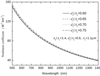
We lastly analyze the case when Λ1 andd1/Λ1 are fixed,
andd2/Λ2is not equal tod1/Λ1. Fig. 6 and fig. 7 show the
simulating result for the case thatΛ1is 1.1µm,Λ2/Λ1=1.4, d1/Λ1=0.6, d2/Λ2=0.60, 0.65, 0.70, and 0.75,
respec-tively. Where fig. 6 is the nonlinear coefficient versus length, and fig. 7 is the waveguide dispersion versus
wave-500 600 700 800 900 1000 1100 1200 1300 1400
-200 -150 -100 -50 0 50 100 150 200
Λ2/Λ1=1.4, d2/d1=1.4, Λ1=1.1µm
Wave
gui
de d
ispe
rsio
n
(
ps.km
-1 .n
m
-1 )
Wavelength (nm)
d1/Λ1=0.50
d
1/Λ1=0.55
d1/Λ1=0.60
d
1/Λ1=0.65
FIG. 5: Waveguide dispersion curves as a function of wavelength for hybrid cladding PCFs.
500 600 700 800 900 1000 1100 1200 1300 1400
40 80 120 160
Λ2/Λ1=1.4, d1/Λ1=0.6, Λ1=1.1µm
d2/Λ2=0.60
d2/Λ2=0.65
d2/Λ 2=0.70
d2/Λ2=0.75
Wavelength (nm)
N
o
n
lin
ear
co
ef
fi
ci
en
t
(
W
-1 .km -1 )
FIG. 6: Nonlinear coefficient curves as a function of wavelength for hybrid cladding PCFs.
length. From fig. 6, we can see when thed2/Λ2increases, the
nonlinear coefficient also increases, but the increment is less. From fig. 7, we can see whend2/Λ2increases, the waveguide
dispersion curve only has a little change. We can findd2/Λ2
is large,γ(λ) is high, and the curve of waveguide dispersion is also suitable for holding the total dispersion flattened, so we selectd2/Λ2is 0.75.
Based on the analysis above, we can find that the cladding structure parametersΛ1, d1/Λ1andd2/Λ2all have influence
on the nonlinear coefficient and the waveguide dispersion. The pitchΛ1has decisive influence on the value of nonlinear
coeffi-cient and the tendency of waveguide dispersion curves,d1/Λ1
also influences the value of nonlinear coefficient and the size and the position of waveguide dispersion, andd2/Λ2generally
influences the value of nonlinear coefficient and has a little effect on the size and position of waveguide dispersion. By re-ducingΛ1or increasingd1/Λ1, we can obtain high nonlinear
higher nonlinear coefficient and maintain the dispersion flat-tened.
500 600 700 800 900 1000 1100 1200 1300 1400
-200 -150 -100 -50 0 50 100 150
Λ2/Λ1=1.4, d1/Λ1=0.6, Λ1=1.1µm
Waveguide dispersion
(
ps.
k
m
-1 .nm -1 )
Wavelength (nm)
d2/Λ
2=0.60
d2/Λ
2=0.65
d2/Λ2=0.70
d2/Λ2=0.75
FIG. 7: Waveguide dispersion curves as a function of wavelength for hybrid cladding PCFs.
3.3. Adjusted results
Now we have an example that designs PCFs with high non-linearity and flattened dispersion properties. In order to predi-gest designing, the total dispersion are expressed as
D(λ)≈Dw(λ)−(−Dm(λ)) (9) whereDm(λ) is the material dispersion. Because the diversi-fication of material dispersion versus wavelength don’t suffer the influence of the cladding structure parameters, so we can obtain flattened dispersion properties by adjusting Dw(λ) to balance−Dm(λ). Combining the computed result above, we can separate the design of flattened dispersion high nonlinear-ity PCF into three steps. Firstly, by adjustingΛ1we can find
the tendency of waveguide dispersion that close the diversi-fication of−Dm(λ)curves, secondly, by changing d1/Λ1we
can adjust waveguide dispersion, thirdly properly increasing d2/Λ2we can gain higher nonlinear coefficient, finally we can
properly changeΛ1,d1/Λ1andd2/Λ2to obtain flattened
dis-persion high nonlinearity PCF.
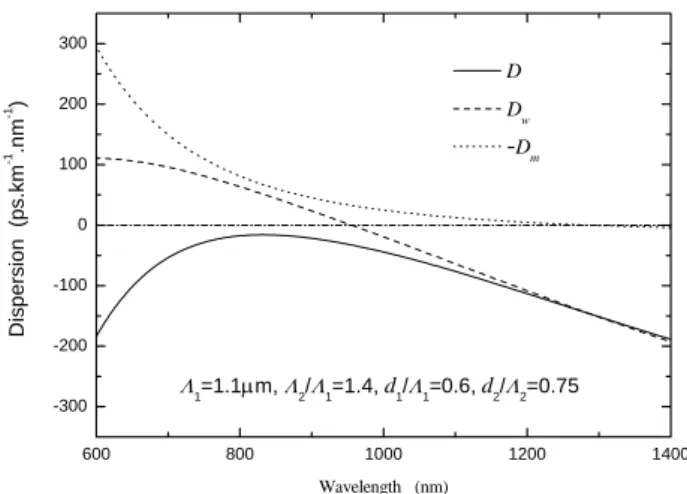
Fig. 8 is the total chromatic dispersion, wave dispersion and material dispersion for modified structure parameters that we design for gaining high nonlinearity dispersion flattened hy-brid cladding PCF. This high nonlinearity dispersion flattened hybrid cladding PCF has the cladding structure parameters:
Λ1=1.1m, Λ2/Λ1=1.4, d1/Λ1=0.6, and d2/Λ2=0.75.
From fig. 8, we can see this hybrid cladding PCF has a flat-tened dispersion profile.
By adjusting the cladding structure parameters, we can ob-tain the high nonlinearity dispersion flattened hybrid cladding PCF. Fig. 9 shows three high nonlinearity dispersion flattened hybrid cladding PCF with different structure parameters. The high nonlinearity hybrid cladding PCF A has the structure pa-rameters: Λ1=1.1µm,d1=0.65µm,Λ2=1.54µm, andd2=
600 800 1000 1200 1400
-300 -200 -100 0 100 200 300
Λ1=1.1µm, Λ2/Λ1=1.4, d1/Λ1=0.6, d2/Λ2=0.75
Dis
p
ersion
(ps.km
-1 .n
m
-1 )
Wavelength (nm)
D
D
w
-Dm
FIG. 8: The total chromatic dispersion, wave dispersion and mate-rial dispersion curves as a function of wavelength for hybrid cladding PCF.
1.05µm; the high nonlinearity hybrid cladding PCF B has the structure parameters:Λ1=1.1µ,d1=0.65µm,Λ2=1.55µm,
andd2=1.15µm; the high nonlinearity hybrid cladding PCF
C has the structure parameters: Λ1=1.1µm, d1=0.65µm,
Λ2=1.58µm, andd2=1.25µm. The hybrid cladding PCFs
all have high nonlinearity and flattened dispersion, and PCF A, PCF B and PCF C has negative dispersion, near zero dis-persion and positive disdis-persion around 800nm, respectively.
70 80 90 100 110
700 750 800 850 900
-80 -60 -40 -20 0 20 40 60
PCF A PCF B PCF C
No
n
lin
ea
r c
o
effic
ien
t
(
W
-1.km -1)
Wavelength (nm)
Di
spe
rsi
on
(ps.km
-1.n
m
-1)
FIG. 9: Nonlinear coefficient curves and the total dispersion curves as a function of wavelength for hybrid cladding PCFs.
nonlinear coefficient and dispersion flattened which is suited for supercontinuum generation.
4. CONCLUSIONS
Using a vectorial FEM, we have computed the nonlinear co-efficient and the dispersion properties of a novel PCF with hy-brid cladding which has different pitches and air-holes diam-eters. The results indicate thatΛ1have decisive influence on
the tendency of waveguide dispersion curves, andd1/Λ1
gen-erally influences the size and position of waveguide dispersion. By reducingΛ1or increasingd1/Λ1, we can obtain high
non-linear coefficient of PCFs, and properly increasingd2/Λ2can
obtain higher nonlinear coefficient and maintain the dispersion flattened. Using a hybrid cladding structure and adjusting the cladding structure parameters, we have obtained the high non-linearity dispersion flattened PCF. The hybrid cladding PCF we proposed is capable to possess of both high nonlinear co-efficient and flattened dispersion. It is useful for the hybrid cladding PCF for their applications in nonlinear fiber optics.
Acknowledgements
The work is supported by the National Natural Science of China with granted No. 60637010.
[1] J. Knight, Nature424, 847 (2003). [2] P. Russell, Science299, 358 (2003)
[3] K. Chow, Y. Takushima, and C. Lin, Electronics Letters,42, 989 (2006).
[4] Z. Zhu and T. Brown, J. Opt. Soc. Am. B,21, 249 (2004). [5] K. Abedin and F. Kubota, Electron. Lett40, 5 (2004).
[6] S. K. Varshney, T. Fujisawa, K. Saitoh, and M. Koshiba, Optics Express,13, 9516 (2005).
[7] A. Zheltikov, Applied Physics B: Lasers and Optics, 84, 69 (2006).
[8] J.Y.Y. Leong, P. Petropoulos, J.H.V. Price, Heike Ebendorff-Heidepriem, S. Asimakis, R.C. Moore, K. E. Frampton, V. Fi-nazzi, X. Feng, T. M. Monro, and D.J. Richardson, J. Lightwave Technol.24, 183 (2006).
[9] K. Saitoh, N. Florous and M. Koshiba, Opt. Lett.,31, 26 (2006). [10] K.K. Chow, C. Shu, Senior Member, Chinlon Lin, and A.
Bjarklev, Photon. Technol. Lett.17, 624 (2005). [11] J.M. Dudley and S. Coen, Opt. Express,12, 2423 (2004). [12] N. Nishizawa, Y. Ito, and T. Goto, Jpn. J. Appl. Phys.42, 449
(2003).
[13] S. Haxha, and H. Ademgil, Optics Communications281, 278 (2008).
[14] J. Wang, C. Jiang, W. Hua, and M. Gao, Optics & Laser Technol. 38, 169 (2006).
[15] S.M. Abdur Razzak, and Yoshinori Namihira, Photon. Technol. Lett.20, 249 (2008).
[16] M. Chen, S. Xie, Optics Communications281, 2073 (2008). [17] N. Florous, K. Saitoh, and M. Koshiba, Opt. Express, 14,901
(2006).
[18] F. Poli, A. Cucinotta, and S. Selleri, Photon. Technol. Lett.16, 1065 (2004).
[19] J. M. Dudley, G. Genty, and S. Coen, Rev. Mod. Phys.78, 1135 (2006).
[20] J. Herrmann, U. Griebner, N. Zhavoronkov, A. V. Husakou, D. Nickel, J. C. Knight, W. J. Wadsworth, P. St. J. Russell, and G. Korn, Phys. Rev. Lett.88, 173901 (2002).