A New Method for the Detection of Singular Points in Fingerprint Images
Filipe Magalhães
INESC Porto, Portugal
Hélder P. Oliveira
INESC Porto, Portugal
Aurélio C. Campilho
INEB, Porto, Portugal
Abstract
Automatic biometric identification based on fingerprints is still one of the most reliable identification method in crim-inal and forensic applications. A critical step in fingerprint analysis without human intervention is to automatically and reliably extract singular points from the input fingerprint images. These singular points (cores and deltas) not only represent the characteristics of local ridge patterns but also determine the topological structure (i.e., fingerprint type) and largely influence the orientation field. Poincaré Index-based methods are one of the most common for singular points detection. However, these methods usually result in many spurious detections. Therefore, we propose an en-hanced version of the method presented by Zhou et al. [13] that introduced a feature called DORIC to improve the de-tection. Our principal contribution lies in the adoption of a smoothed orientation field and in the formulation of a new algorithm to analyze the DORIC feature. Experimental re-sults show that the proposed algorithm is accurate and ro-bust, giving better results than the best reported results so far, with improvements in the range of 5% to 7%.
1. Introduction
Fingerprint images are directionally oriented patterns formed by ridges and valleys that can be captured from a finger with a multitude of sensors, particularly, capacitive, optical, thermal sweeping and ultrasonic. Fingerprints are unique to each individual and have long been widely used as a biometric identification tool [10]. The singular points -cores and deltas - are the most important topological global characteristics of a fingerprint [12]. The singular point area is defined as a region where the ridge curvature is higher than normal and where the direction of the ridge changes rapidly.
These singular points can constitute a powerful basis for the classification of fingerprint types [5], as well as for fin-gerprint alignment and orientation field modeling [4, 11].
Several methods for detecting and analyzing singular points in fingerprint images have been devised [1, 7].
However, the most widely used tool for singularity ex-traction is the Poincaré Index, since it is relatively simple to compute and robust to image rotation. The first application of Poincaré indices to fingerprint images was presented by Kawagoe and Tojo [7].
Poincaré Index-based methods consider the discontinu-ous orientation distribution around singular points, by com-puting the sum of the orientation changes along a closed circle around a point to judge whether it is a singular point. However, many spurious detections usually arise, deriving from low quality images, scars, smudges, etc. that ex-hibit orientation patterns closely resembling a true singu-lar point. Even after postprocessing, many of these spuri-ous detections still remain since only local information is used. Therefore, to accurately distinguish the genuine sin-gular points, global discriminative information should be used in the detection process.
In order to address these problems we adopt the fol-lowing strategy: 1) to calculate the Poincaré Index using a smoothed orientation field, in order to reduce the number of spurious points detected; 2) remove some spurious points, regarding some core-delta topological constraints, with the use of postprocessing steps; and 3) to use a recent feature called DORIC (Differences of the ORIentation values along a Circle) [13], which provides more discriminative informa-tion that can be further used to remove remaining spurious points.
Experimental results showed that the proposed algorithm is accurate and robust for a wide variety of fingerprint types. Compared with previous research, we achieved better detec-tion results with this new method.
The rest of this paper is organized as follows: Section 2 provides an insight into the mathematical background of the Poincaré Index and describes in detail the several parts of the proposed algorithm. In Section 3 the principal re-sults are presented as well as a comparison between the state-of-the-art and the proposed algorithm. These results are analyzed and discussed in Section 4 and, finally, some conclusions are presented.
2. Methods
In this section the methods used in the devised strategy for the detection of singular points in fingerprint images will be presented.
2.1. Poincare Index mathematical background
A singularity can be defined as a local region of the fin-gerprint where the ridge pattern has special properties mak-ing it visually prominent. To identify the principal smak-ingular points on a fingerprint, i. e. cores and deltas, a Poincaré Index based method can be used.
In Figure 1 it is presented the vector field and the Poincaré Index of three typical patterns.
Figure 1: Three typical vector field patterns. a) No singu-larity, I(γ) = 0. b) Circle (Core), I(γ) = 1. c) Saddle (Delta), I(γ) = −1.
A core is defined by a turning point of an inner-most ridge and a delta is a place where two ridges running side-by-side diverge. Using the Poincaré Index, a value of +1 can be assigned to a core, a value of −1 to a delta and 0 to a non-singularity.
Let us consider V (x, y) = Φx(x, y) + i · Φy(x, y),
where V (x, y) is a continuous 2D vector field, Φx(x, y)
and Φy(x, y) are its real and imaginary components,
respec-tively. The Poincaré Index I(γ) of V (x, y) along closed path γ can be computed by:
I(γ) = 1
2 · π Z
(x,y)∈γ
dφ(x, y), (1)
where φ(x, y) represents the angle on each (x, y) point of the vector field along γ and φ(x, y) ∈ [0, 2π[. Usually, the integration is taken counterclockwise.
2.2. Proposed algorithm
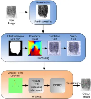
In Figure 2 it can be seen the algorithm’s block dia-gram. In the following subsections its principal steps are described.
2.2.1 Normalization
In this step the input image is normalized in order to have a specific mean and standard deviation. The main purpose of this step is the contrast enhancement to reduce the vari-ations of the gray-level values along ridges and valleys, to
Figure 2: Proposed algorithm flowchart.
facilitate the next processing steps, particularly the orienta-tion field computaorienta-tion.
Let I be a gray-level image and I(x, y) the pixel value at the (x, y) position. µ denotes the estimated mean and σ the estimated standard deviation of I. The normalization procedure is applied to the image pixels using the following equation [2]: In(x, y) = µn+ q σn(I(x,y)−µ)2 σ , if I(x, y) > µ µn− q σn(I(x,y)−µ)2 σ , otherwise, (2)
where In(x, y) represents the value for each normalized
gray-level pixel, and µn and σn the desired normalized
mean and standard deviation values, respectively.
2.2.2 Effective region detection
In order to reduce the size of the region to be processed and, consequently, the computational time, an effective region detection algorithm was implemented. Within this algo-rithm, as usual in image processing, the normalized image was broken into blocks of size (Bz×Bz), and the mean and
the standard deviation of each block were evaluated. If the standard deviation was above a threshold tσit was deemed
part of the fingerprint.
In this process some morphological operators were also included, such as, erosion and flood-fill. The erosion was applied in first place in order to create a ”safety zone”, pre-venting the posterior occurrence of spurious detections on the borders of the fingerprints.
2.2.3 Smoothed orientation field
The orientation image represents an intrinsic property of the fingerprint images and defines invariant orientation regions for ridges and valleys in a local neighborhood. Many meth-ods were devised for the computation of the orientation field and many are supported by the fact that fingerprints can be seen as an oriented texture [6, 7]. In this work, we chose to compute the orientation field using a least mean square orientation estimation [3] (see equation (3)).
θ(x, y) = 1 2 · tan −1 W X x=1 W X y=1 Ψ1(x, y) W X x=1 W X y=1 Ψ2(x, y) (3) Ψ1(x, y) = 2 · Gx(x, y) · Gy(x, y) Ψ2(x, y) = G2x(x, y) − G 2 y(x, y),
where θ(x, y) is the least square estimate of the local ridge orientation at the block with size W × W , centered at pixel (x, y). Gx(x, y) and Gy(x, y) represent the gradient along
the x and y directions, respectively.
Due to the presence of noise, corrupted ridge and val-ley structures in the input image, the estimated local ridge orientation, θ(x, y), may not always be correct. Since lo-cal ridge orientation varies slowly in a lolo-cal neighborhood where no singular points appear, a low-pass filter can be used to modify the incorrect local ridge orientation. In order to smooth the initial orientation field a Gaussian filter was implemented with size Gz and standard deviation equal to
σg[2, 13].
After the computation of the orientation field for each pixel, the vector field V (x, y) can be computed using the following equation:
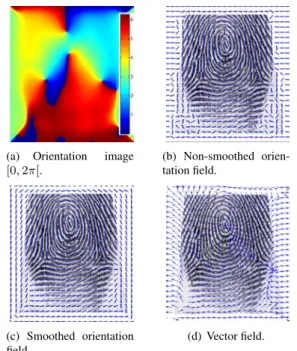
V (x, y) = cos(2 · θ(x, y)) + i · sin(2 · θ(x, y)), (4) In Figure 3 it can be seen some results for the computa-tion of the orientacomputa-tion image and respective non-smoothed and smoothed orientation fields and vector field.
2.2.4 Singularity detection using the Poincaré Index The pixels can be defined as cores, deltas or non-singularities depending on their Poincaré Index values.
The Poincaré Index method can usually detect nearly all true singular points, when it is computed in a small region, but this can also lead to the detection of too many spurious points. If the detection is made into a very large region, true singular points could be missed. To increase the correct detection rate and reduce the detection of spurious points it
(a) Orientation image [0, 2π[. (b) Non-smoothed orien-tation field. (c) Smoothed orientation field. (d) Vector field.
Figure 3: Orientation image (a) and respective orientation fields (non-smoothed (b) and smoothed (c)) and vector field (d).
is necessary to establish a compromise in the choice of the optimal region size.
For the computation of the Poincaré Index value (IP), a
circle, with a specific radius (rp) and Nppoints, is centered
in each pixel of the fingerprint effective region. Then, the Poincaré Index is computed as the sum of the differences between the orientations of two consecutive points in the circle (oi+1and oi), as stated in the following equation,
be-ing that a counterclockwise direction is assumed:
IP = 1 π N −1 X i=1 f (oi+1− oi) = 1 π N −1 X i=1 f (δoi), (5)
where oN = o1, oi∈ [0, π[, and f is defined as:
f (x) = −x, |x| ≤π 2 π − x, x > π 2 π + x, x < −π2 (6)
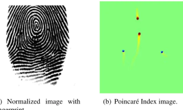
Figure 4 presents the output image after the Poincaré In-dex method step.
2.2.5 Feature postprocessing
After the singular points detection using the Poincaré In-dex, as previously stated, some spurious points may still remain. In order to reduce the amount of possibly false de-tected points a postprocessing step was introduced.
(a) Normalized image with fingerprint.
(b) Poincaré Index image.
Figure 4: Detection of the singular points in image (a) using the Poincaré Index. The cores are represented in red while the deltas are represented in blue.
In the first place, if two or more singular points of the same type, cores or deltas, are close to each other, within a certain distance (d), they become to be represented by a centroid. The second postprocessing step, determines if a core and delta are too close to each other. If they are closer than a certain distance (ds) both points are removed.
During the experimental tests, we noticed that these steps were rarely used. This is supported by the use of the smoothed orientation field, and, therefore, they will only be needed in very particular occasions, for instance, when in the presence of low-quality images, or fingerprints with scars, which introduce strong ”artifacts” to the orientation field. If no smoothing is applied, this postprocessing phase reveals itself to be very important in the removal of spurious points.
2.2.6 DORIC feature
In order to remove spurious detections while preserving a good detection rate, Zhou et al. [13] proposed a novel fea-ture extended from the Poincaré Index, which can be used to verify the trueness of each detection after using the Poincaré Index and the postprocessing algorithms.
The Poincaré Index is the sum of δoiand it does not
de-scribe completely a singular point. When there are creases, scars, or smudges in the fingerprint images, the Poincaré Index will result in the detection of spurious singular points that even after the postprocessing are not removed.
Similar to the Poincaré Index method, the DORIC fea-ture is computed along a closed circle, centered in each of the detected singular points, with a specific radius (rd) and
Ndpoints.
The novel feature, called DORIC, consists of all the δoi,
and, therefore, it can describe the singular points more com-pletely. Since the orientation field is defined in [0, π[, the DORIC feature will exhibit one positive pulse, with height near π, for a core and a negative pulse, with height near −π, for a delta. Although the noise around the true sin-gular points may alter the curves a little, it can be clearly
distinguished the difference between true and spurious sin-gular points. Two DORIC features of true sinsin-gular points are illustrated in Figure 5.
(a) DORIC feature for a true delta.
(b) DORIC feature for a true core.
Figure 5: DORIC features of two true singular points. After the postprocessing phase, there is only one singular point for any fairly large region. Thus, it is more adequate to compute the DORIC features along a large circle. This enables the use of a higher number of points in the circle which will cause the DORIC feature curves to become more continuous and much easier to analyze.
Finally, to classify the remaining singular points as true or spurious points, the following algorithm was devised: Algorithm 1 Pseudo code algorithm to classify the remain-ing sremain-ingular points as true or spurious points.
for each of the remaining singular points (P1, P2, ...) do DORIC(Pk) = [δo1, δo2, δo3, ..., δoN −1];
if ∃!i ∈ [1, N − 1], that |δoi| ∼= π AND ¬∃ j 6= i, j ∈ [1, N − 1], that |δoj| > π/6 then
keep Pk else remove Pk end if end for
3. Experimental results
The proposed method was tested on four public databases (FVC02 DB1 and DB2 [8] and FVC04 DB1 and DB2 [9]) and one database created by the authors. Each FVC database has 80 images, relative to 10 fingers and 8 prints of each finger. The database created by the authors consists of 70 images, corresponding to 1 image of each fin-ger from 7 individuals. These images were acquired with an optical sensor (Microsoft Fingerprint Reader - model 1033) without any special effort on image quality and cleaning procedures.
For the validation of the detection results, the authors in-dependently analyzed each image and registered the occur-rence of cores and deltas. If there was some disagreement between their decisions, a joint decision would be made.
For the results presented, the detection rate is defined as the ratio of truly detected singular points to all ground truth singular points. The miss rate is defined as the ratio of the number of missed singular points to the number of all ground truth singular points. The false alarm rate is defined
as the number of falsely detected singular points versus the number of all ground truth singular points. If all singular points are detected and there are no spurious singular points in a fingerprint, the fingerprint is said to be ”correctly” de-tected [13].
During the implementation phases, all the parameters were experimentally tuned using the FVC02 DB1 as a ”training” set. The most adequate values found are pre-sented in TABLE 1.
M ethod P arameter V alue
N ormalization mean µn 0
stdev σn 1
Ef f ec. region detect. block size Bz 16 stdev threshold tσ 0.3
Smoothed orient. f ield
block size W 10 Gaussian stdev σg 10 Gauss. block size Gz 60 Sing. points detection radius rp 5 number points Np 8
F eat. postprocess.
dist. core − core d 16 dist. delta − delta d 16 dist. core − delta ds 20 DORICf eature radius rd 10 number points Nd 50
Table 1: Values of the parameters used in the algorithm. When possible, the obtained results were compared to those exhibited by Zhou et al. [13], as they state their work presented better results than the best reported ones.
In Table 2, 3, 4 and 5, the obtained results are presented (all values are in percentage).
P roposed Zhou0s [13]
Cores
Detection rate 100 95.78 M iss rate 0 4.22 F alse alarm rate 1.25 2.27
Deltas
Detection rate 97.50 96.98 M iss rate 2.50 3.02 F alse alarm rate 1.25 9.97 F ingerprint precision 95.00 88.88
Table 2: Comparison results of different detection algo-rithms on FVC02’s DB1.
P roposed Zhou0s [13]
Cores
Detection rate 98.75 95.51 M iss rate 1.25 4.49 F alse alarm rate 7.50 8.45
Deltas
Detection rate 95.00 90.88 M iss rate 5.00 9.12 F alse alarm rate 1.25 12.54 F ingerprint precision 86.25 81.25
Table 3: Comparison results of different detection algo-rithms on FVC02’s DB2.
DB1 DB2
Cores
Detection rate 100 90.00 M iss rate 0 10.00 F alse alarm rate 3.75 17.50
Deltas
Detection rate 96.25 97.50 M iss rate 3.75 2.50 F alse alarm rate 1.25 8.75 F ingerprint precision 92.50 67.50
Table 4: Results with the proposed algorithm on FVC04’s DB1 and DB2.
Cores
Detection rate 95.71 M iss rate 4.29 F alse alarm rate 5.71
Deltas
Detection rate 97.14 M iss rate 2.86 F alse alarm rate 2.86 F ingerprint precision 84.29
Table 5: Results with the proposed algorithm on the au-thors’ database.
Some images of the results obtained with the proposed algorithm are presented in Figure 6.
(a) (b)
(c) (d)
Figure 6: Results obtained with the proposed algorithm for different types of fingerprint images and topologies.
The results were obtained with M AT LAB with anR Intel CoreR T M2 Duo CP U @2.50GHz and 3GB of RAM . In average the processing time was approximately 10 seconds for each fingerprint image with sizes ranging from 296 × 560 to 640 × 480, depending on the database.
4. Analysis and discussion
From the analysis of Figure 6, it can be seen that our al-gorithm behaves well for a wide variety of images and fin-gerprint types, even in the presence of scars (Figure 6(a)), rotations (Figure 6(b) and 6(c)) and low-quality images (Figure 6(d)).
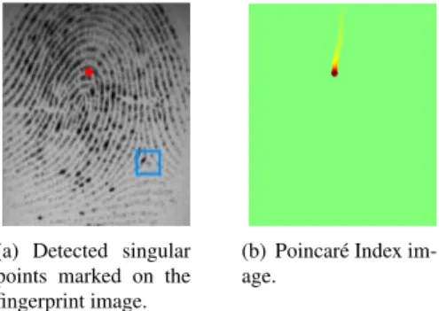
However, there are some cases where the algorithm fails. For instance, in Figure 7(a) it is missing one delta. This can be justified by the fact that the Poincaré Index calculation did not have revealed any singularity where expected (see Figure 7(b).
In Figure 8(a), we can see one spurious delta that was not removed by the proposed algorithm. Its DORIC feature can be seen in Figure 8(b) and it can be seen that it closely resembles the trace of a true delta, therefore, it was not pos-sible for the proposed algorithm to remove it.
(a) Detected singular points marked on the fingerprint image.
(b) Poincaré Index im-age.
Figure 7: Missed detection of a singular point (Delta) by the Poincaré Index. The blue square marks the expected location of the missed delta.
(a) Detected singular points marked on the fingerprint image.
(b) DORIC feature of the spu-rious delta.
Figure 8: One example of a spurious delta that was not re-moved with the use of the DORIC feature. The blue square identifies the over detected delta.
From the results of Table 2 and 3 it can be stated that, relatively to the FVC02 databases, the proposed algorithm promoted the achievement of better results than those pre-sented by Zhou et al. [13]. Relatively to the results obtained for the remaining databases (see Table 4 and 5), it can be said that the results were also very good.
5. Conclusion
This work presented a new method for the detection of singular points in fingerprint images. The proposed algo-rithm has two fundamental parts: 1) detection of singular-ities using the Poincaré Index on a smoothed orientation field, which contributed since the beginning to the reduc-tion of the number of spurious points detected; and 2) use the DORIC feature to improve the discriminative ability of the Poincaré Index-based detection.
From the analysis of the obtained results we can state that the main causes of errors are deltas and cores located in the fingerprints’ borders, as well as low-quality images, scars, creases, smudges, etc. that will lead to the obtention of erroneous orientation fields, which are crucial to the de-tection of the singular points.
As a future improvement, some of the parameters, par-ticularly those referring to distances, could be adaptively set. One possible approach would be to detect the width of ridges and valleys and, therefore, proportionally set the
parameters. Despite this has not been done yet, the pro-posed algorithm was able to provide very good results for a wide variety of fingerprint types and images, when com-pared with other approaches recently published.
Acknowledgements
The authors would like to thank Fundação para a Ciên-cia e Tecnologia (FCT)for the financial support of the PhD grants SFRH/BD/45380/2008 and SFRH/BD/43772/2008.
References
[1] G. A. Drets and H. G. Liljenström. Intelligent biometric tech-niques in fingerprint and face recognition. CRC Press, New York, 1999.
[2] L. Hong, Y. Wan, and J. A. Fingerprint image enhancement: algorithm and performance evaluation. IEEE Transactions on, Pattern Analysis and Machine Intelligence, 20(8):777– 789, 1998.
[3] A. Jain, L. Hong, and R. Bolle. On-line fingerprint verifica-tion. IEEE Transactions on Pattern Analysis and Machine Intelligence, 19(4):302–314, 1997.
[4] G. Jinwei and Z. Jie. A novel model for orientation field of fingerprints. In Proceedings IEEE Computer Society Confer-ence on Computer Vision and Pattern Recognition, volume 2, pages II–493–8, 2003.
[5] K. Karu and A. K. Jain. Fingerprint classification. Pattern Recognition, 29(3):389–404, 1996.
[6] M. Kass and A. Witkin. Analyzing oriented patterns. Com-put. Vision Graph. Image Process., 37(3):362–385, 1987. 27996.
[7] M. Kawagoe and A. Tojo. Fingerprint pattern classification. Pattern Recognition, 17(3):295–303, 1984.
[8] D. Maio, D. Maltoni, R. Cappelli, J. L. Wayman, and A. K. Jain. Fvc2002: Second fingerprint verification competition. In Proceedings 16th International Conference on Pattern Recognition, volume 3, pages 811–814, 2002.
[9] D. Maio, D. Maltoni, R. Cappelli, J. L. Wayman, and A. K. Jain. Fvc2004: Third fingerprint verification competition. In Proceedings International Conference on Biometric Authen-tication (ICBA), pages 1–7, Hong Kong, 2004.
[10] S. Pankanti, S. Prabhakar, and A. K. Jain. On the individu-ality of fingerprints. IEEE Transactions on Pattern Analysis and Machine Intelligence, 24(8):1010–1025, 2002. [11] B. G. Sherlock and D. M. Monro. A model for interpreting
fingerprint topology. Pattern Recognition, 26(7):1047–1055, 1993.
[12] V. S. Srinivasan and N. N. Murthy. Detection of sin-gular points in fingerprint images. Pattern Recognition, 25(2):139–153, 1992.
[13] J. Zhou, F. Chen, and J. Gu. A novel algorithm for detecting singular points from fingerprint images. IEEE Transactions on Pattern Analysis and Machine Intelligence, 31(7):1239– 1250, 2009.