1.Shanmugha Arts, Science, Technology & Research Academy – School of Mechanical Engineering – Thanjavur/TN – India.
Correspondence author: Muniyandi Venkatesan | Shanmugha Arts, Science, Technology & Research Academy – School of Mechanical Engineering | Thanjavur/TN 613401 | Thanjavur/TN – India | E-mail: [email protected]
Received: Aug. 21, 2017 |Accepted: Oct. 26, 2017 Section Editor: John Tharakan
ABSTRACT: Hydrogen peroxide is a chemical compound which is commonly used as a disinfectant at lower concentrations. The chemical is called as a green propellant for space applications. Water and oxygen are the products after self-decomposition of the compound at higher concentrations. The reaction rate at lower concentrations can be enhanced by using catalysts for faster reaction rates. In the present study, an experimental analysis of the reaction rate of hydrogen peroxide (6% by volume) with silver catalyst for varying flow rates is detailed. Reaction takes place in a long cylindrical borosilicate glass tube of diameter 2.50 mm. Separation of product mixture takes place in an enlarged tube of diameter 5.50 mm. Various two phase flow patterns formed after decomposition reactions are identified by images captured using high speed camera. Length of oxygen slug formed after catalytic reaction is measured by employing Image processing techniques.
KEYWORDS: Hydrogen peroxide, Silver catalyst, Two phase flows, Decomposition.
INTRODUCTION
Space exploration for distant planets resulted in advances in micro propulsion technologies over the past few decades. A detailed understanding of digital propulsion technology is required for positioning of micro/nano satellites which are of weight ranging from 10 – 50 kg and 0.1 – 10 kg, respectively. Such satellite systems require controlled thrust for accurate positioning, adjustment of micro-altitude and orbit control. The advantages of small satellites including low operational cost and long lifetime were discussed by Nikolova (2005). With micro propulsion technology, space missions are now possible with a constellation of nano/micro satellites replacing the traditional larger satellites effectively and efficiently with minimal fuel consumption. Several applications of micro propulsion are under study to ensure the advantages besides the limitations in system size, mass, volume and power. Such satellites employ micro thrusters in place of conventional thrusters where low impulse is required and associated thrust level is of the order of micro to milli-Newton. For the effective functioning of such satellites, monopropellant is preferred. A monopropellant such as hydrogen peroxide, on self decomposition or enhanced decomposition with a catalyst, initiates propulsive reaction and produce thrust. There is no need for ignition or combustion. Different mono-propellants commonly used are hydrazine and hydrogen peroxide. Wernimont (2006) made a comparative study on few monopropellants. It was concluded that hydrogen peroxide had better performance in density impulse terms when compared to other mono propellants. Hydrogen
Mini-channel Two Phase Flow of Hydrogen
Peroxide: Decomposition with Silver Catalyst
Suresh KalaThirumalaikumaran1, Ranganathan Suwathy1, Muniyandi Venkatesan1
Thirumalaikumaran SK; Suwathy R; Venkatesan M (2018) Mini-channel Two Phase Flow of Hydrogen Peroxide: Decomposition with Silver Catalyst. J Aerosp Technol Manag, 10: e2818. doi: 10.5028/jatm.v10/943.
How to cite
Thirumalaikumaran SK http://orcid.org/0000-0003-0309-4965
Suwathy R http://orcid.org/0000-0002-2715-3432
peroxide is a chemical compound which consists of oxidizer mixed with water molecules and undergoes self-decomposition in the presence of heat or catalyst.
Various materials including silver, platinum, manganese dioxide, and ferric chloride can be used as a catalyst for enhancing decomposition rate of hydrogen peroxide. The complexity arises in designing the catalyst arrangement for precise control of thrust production. The catalytic material can be coated along the surface or can be made as a bed in which the catalyst flows. Plumlee et al. (2007) developed a silver coated micro channel and analysed the decomposition of hydrogen peroxide. The targeted impulse bit in such a design could be achieved with discrete two phase flow of gas liquid mixture. The decomposition of hydrogen peroxide with perovskites as catalyst was examined by Soleymani et al. (2011). It was reported that catalytic activity increased with increase in calcium. Xu et al. (2007) enhanced the catalytic reaction in two phase flow by formation of gas slugs.
The design of a micro propulsion system for complete decomposition with optimized parameters can be done with computational fluid dynamics (CFD). Volume of fluid method was used to track the point of interface of two fluids (Fluent 2004). The characteristics of catalytic decomposition was done using Species transportation model of the commercial code Fluent. Eddy dissipation model was implemented to predict the rate of reaction (ANSYS Fluent 2009). The passage of hydrogen peroxide through a catalytic mesh can be modelled as a porous medium. Such approach was used by Wang et al. (2013a) to create a 2-D model of single phase flow of hydrogen peroxide. The study was focused on decomposition inside the porous medium (silver catalyst bed).
Few studies are reported in literature to measure the micro thrust produced at the end of the nozzle. Wang et al. (2013b) developed a thrust measuring system by employing a leaf spring arrangement. The designed system was capable of testing micro thrusters of mass up to 300 g. Shrisat et al. (2013) presented the extinction behaviour, discharge characteristics of the thrust chamber and measured thrust with the thrust stand.
Chiappetta et al. (2000) reported that the oxygen produced from catalytic decomposition of HTP (High Test Peroxide) could be used for power production. The system was used as a HTP gas generator for rocket propulsion. Xiao et al. (2016) fabricated a mini generator using super hydrophobic rotor placed inside aqueous hydrogen peroxide containing platinum catalyst. The decomposition produced oxygen bubble that rotate the magnets inside and generated electromotive force. It was proposed as a feasible way of power generation through energy transformation from chemical to mechanical energy, and then mechanical to electrical energy. Han et al. (2015; 2016) used hydrogen peroxide as a diesel reformer in Unmanned Underwater Vehicle (UUV) and submarines which operated in low oxygen level environment. Hasvold et al. (1999) expanded the sea water battery life using hydrogen peroxide as an alternate oxidant to provide sufficient power.
The above mentioned studies detail the various applications of hydrogen peroxide in propulsion, under water vehicles, power generation, and in providing fresh oxygen for humans and plants. A thorough understanding of decomposition mechanism of hydrogen peroxide is essential for designing of micro thrusters. The objective of the present study is to measure the amount of oxygen released during catalytic decomposition of 6% hydrogen peroxide with silver as a catalyst. The catalytic reaction results in formation of two phase flow with oxygen (Gas phase) and Reacted liquid (Liquid phase). The two phase flow regimes are recorded and identified using high speed photography and characteristics of the slug flow pattern is analysed. Such data is necessary for design of mini/micro catalytic reactors which can be used for accurate thrust control.
EXPERIMENTAL SETUP
initiated on interaction between hydrogen peroxide and silver. The reacted hydrogen peroxide is in liquid phase and collected in a well sealed tank via a drain tube connected to the horizontal outlet of T-section. The oxygen in gas phase escapes through the vertical outlet of T-section. The volume of oxygen is measured using a tank fully filled with water. The tank is connected to another measuring jar in which water drips as oxygen fills up. A high-speed AOS PROMON 501 colour camera coupled with a NAVITAR ZOOM lens (Model 7000) is fixed near to the front face of the reaction tube for continuous monitoring of reaction happening inside the tube. The camera is capable of capturing images at a frame rate of 6000 fps. Figure 2 shows the line sketch of the experimental setup.
(1)
Figure 2. Experimental setup. Figure 1. Rolled silver catalyst.
T-section
High speed camera
Syringe pump Silver catalyst
Measuring jar Gas collecting tank
Liquid collecting tank
CHEMICAL REACTIONS
Hydrogen peroxide is a self-decomposable fluid with low activation energy. In this analysis, a silver catalyst is included to accelerate the decomposition rate of low concentration hydrogen peroxide (6% by volume). During the process of decomposition, water vapour and oxygen are formed with release of heat energy. The reaction is exothermic (Eq. 1).
2H2O2(l) Under catalytic decomposition 2H2O(g) + O2(g)
RESULTS AND DISCUSSION
The various flow patterns observed during the reactions and the method of slug length measurement is detailed for a mini channel of 2.50 mm. Two phase flow patterns section discusses the flow patterns formed during the reactions for different flow rates. The following section discusses measurement of slug dimensions. The amount of oxygen collected for various flow rates is discussed in sequence and finally the amount of reacted liquid collected for various flow rates is detailed.
TWO PHASE FLOW PATTERNS
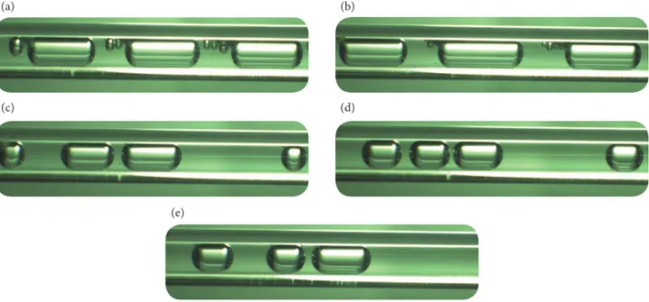
The experimental setup is checked thoroughly for leakages and completely sealed. Before letting the flow inside the reaction tube, the water collector tank and reacted liquid collector tank is made empty. The syringe pump is set to 10 mL/h as an initial flow rate and an amount of 15 mL of hydrogen peroxide is initially filled in the syringe and allowed to flow. During filling, enough care is taken so that the air trapped inside the syringe is removed completely. The chemical compound decomposes and forms large amounts of oxygen in the form of bubbles and slugs with small amounts of reacted liquid. Two phase flow regimes are observed because of the decomposition with mixing of immiscible fluids as liquid phase (reacted liquid) and gas phase (oxygen). The slug flow regime is identified for a flow rate of 10 mL/h. The length of this regime is relatively long when compared to other flow rates as shown in Fig. 3a. The same procedure is incorporated for the other cases with different flow rates of hydrogen peroxide. The flow rates taken in to consideration are 20, 30, 40, 50 mL/h. The predominant flow regime observed is slug flow. The slug length starts decreasing with increase in the flow rate. Figure 3b-3e shows the two phase flow regimes for different flow rates of 6% concentration of hydrogen peroxide for 15 mL of total volume.
Figure 3. Flow regime: (a) 10 mL/h; (b) 20 mL/h; (c) 30 mL/h; (d) 40 mL/h; (e) 50 mL/h.
(a) (b)
(c) (d)
(e)
MEASUREMENT OF SLUG DIMENSION
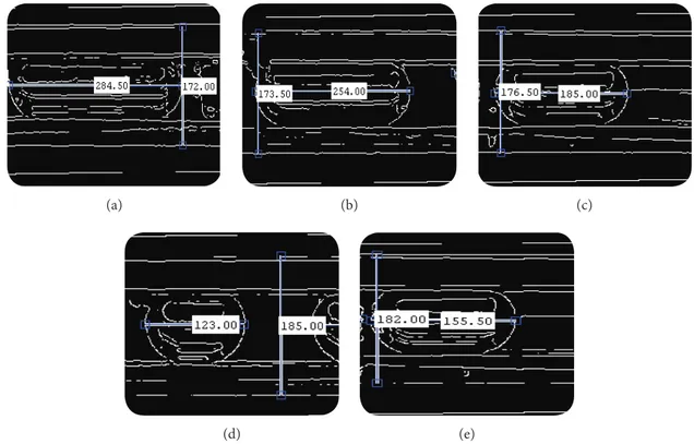
At first, the image is converted from RGB to gray scale image using “rgb2gray” command and the converted image intensity is adjusted using “imadjust” command to enhance it. Apart from the different edge detection techniques, Canny edge detection technique is chosen because of its effectiveness. The pixel distance between the edges of the length of the slug is measured horizontally and for reference the outer diameter of the reaction tube is measured in the pixel distance. Thereby original dimension of slug length is calculated by comparing it with known dimension of the outer diameter of the tube. All the flow regimes formed with different flow rates are processed using the same method. Figure 4 shows the processed images for different flow rates where the horizontal pixel dimension stands for the slug length and the vertical pixel dimension stands for the outer diameter of the reaction tube.
Figure 4. Processed images for different flow rates: (a) 10 mL/h; (b) 20 mL/h; (c) 30 mL/h; (d) 40 mL/h; (e) 50 mL/h.
(d)
(a) (b) (c)
(e)
As this decomposition is a transient reaction, slugs formed in the reaction tube have lengths which vary slightly. In order to avoid errors during calculations, the length of various slugs formed during the reaction at various time intervals is recorded. Images of slugs are taken and processed using image processing techniques. The size of each slug is noted. The average dimension is taken from all the slugs formed at each flow rate and then tabulated. Figure 5a shows the slug length for different flow rates.
The formation of two phase flow depends on the contact area and contact time of hydrogen peroxide with silver. When the flow rate increases, there is less contact time and hence the reaction is incomplete. Because of the less contact time, the slug length decreases with increase in flow rate as shown in Fig. 5a.
MEASUREMENT OF OXYGEN
fully filled with water. Whenever fresh oxygen enters into the tank, it forces the water toward the drain tube and the water from the drain tube is collected in a separate measuring jar which is emptied initially. The continuous generation of oxygen in two phase flow regimes results in continuous dripping of water in the measuring jar. After the completion of reaction for 15 mL amount of hydrogen peroxide, the water collected in the measuring jar is measured in terms of volume. Oxygen measured for different flow rates of hydrogen peroxide is shown in Fig. 5b. As illustrated in the graph, volume of the oxygen collected reduces with increase in flow rate of hydrogen peroxide. Higher the flow rate, reaction becomes incomplete and the slug size also decreases as discussed in Mesurement of slug dimention section.
Figure 5. Flow rate em function of: (a) Slug length; (b) Volume of oxygen; (c) Reaction percentage; (d) Volume of reacted liquid; (e) Concentration of unreacted hydrogen peroxide in reacted liquid.
0 2 4 6 8 10
0 10 20 30 40 50 60
S
lug L
en
g
th (mm)
Flow Rate (mL/h)
0 10 20 30 40 50 60
Flow Rate (mL/h)
0 10 20 30 40 50 60
Flow Rate (mL/h)
0 5 10 15 20 25 30 35 40 45 50
0 10 20 30 40 50 60
V o lume o f O xy ge n (mL)
Flow Rate (mL/h)
0 10 20 30 40 50 60
Flow Rate (mL/h)
0 2 4 6 8 10 12 14 16 R eac ti o n (%) 14.975 14.98 14.985 14.99 14.995 15 V o lume o f R eac te d L iq ui d (mL) 5 5.1 5.2 5.3 5.4 5.5 5.6 5.7 5.8 5.9 C o nc en tr at io n (%)
CALCULATION ON REACTED LIQUID MEASUREMENT
The amount of reacted liquid in the collecting tank is approximately equal to the amount of hydrogen peroxide reacted in the tube. This quantity supplied can be known from syringe pump. In order to find the exact quantity of reacted liquid, a theoretical calculation is made on volume basis. In the experiment, the collected reacted liquid contains reacted water, reacted hydrogen peroxide
(a)
(c)
(e)
(b)
and water which is already present in 6% concentration of hydrogen peroxide. Molar based calculations are incorporated during decomposition reaction of hydrogen peroxide to calculate the volume of individual liquid products from the product mixture.
2H2O2(l) Under catalytic decomposition 2H2O(l) + O2(g)
From the stoichiometric reaction equation (Eq. 2), for 6% concentration of hydrogen peroxide, two moles of hydrogen peroxide on the reactant side after catalytic reaction give out two moles of water and one mole of oxygen as products. Once oxygen collected is known experimentally, other fluids can be calculated based upon molar analysis.
Initially, water is presented as 14.37 mL in 15 mL of 6% concentration hydrogen peroxide mixture and the rest is pure hydrogen peroxide. So, for all the cases of flow rates, water presence in the reacted liquid will be constant as 14.37 mL. The amount of oxygen and water collected in the measuring jar experimentally is used for finding reacted and unreacted hydrogen peroxide. The flow rates are measured using a precision balance (Shimadzu corporation (AUX220 model)) having a measuring range of 220 gms with minimum display of 0.1 mg. The ratio of used amount of hydrogen peroxide (reacted) to the total amount of hydrogen peroxide present in the 15 mL solution can be quantified using a parameter called reaction percentage. Figure 5c shows the graph plotted between reaction percentage and the flow rates. As the reacted hydrogen peroxide and amount of oxygen collected are proportional to each other, the graph shows that the reaction percentage is decreasing with increase in flow rate of the hydrogen peroxide. Reaction percentage is also dependent on the amount of hydrogen peroxide used during decomposition and it will vary with change in the amount of catalyst and method of mixing (design of catalyst bed) during the reaction.
The unreacted hydrogen peroxide can be calculated from difference between total hydrogen peroxide present in 15 mL and hydrogen peroxide which underwent decomposition. The reacted water can also be theoretically calculated from the relationship between the difference in amount of reactant and products. The reacted water, reacted hydrogen peroxide, and water which is already present in 15 mL solution are added together to get the volume of reacted liquid. Figure 5d shows the graph plotted between volumes of reacted liquid versus flow rate of the 6% concentration of hydrogen peroxide.
The unreacted hydrogen peroxide present in the reacted liquid can be reused for the decomposition using the same silver catalyst. The concentration is calculated from the ratio of unreacted hydrogen peroxide to the amount of reacted liquid. As the reacted liquid is a varying parameter with flow rates, the unreacted hydrogen peroxide also varies with change in flow rate. Thus the percentage concentration of unreacted hydrogen peroxide is calculated for all flow rates.
The amount of percentage concentration of hydrogen peroxide in the reacted liquid with varying flow rates of the hydrogen peroxide is shown in Fig. 5e. The percentage concentration of the hydrogen peroxide present in the reacted liquid is increasing with increase in flow rates because the reaction time given for the decomposition of hydrogen peroxide is shorter. When the flow rate is increased, the amount of unreacted hydrogen peroxide is increased.
The above result shows that the reaction rate of hydrogen peroxide can be further enhanced by proper design of catalytic reactor. Also, flow rate of hydrogen peroxide plays a vital role in amount of oxygen formed which is significant for precise thrust production. More studies need to be done to have slugs of desired length by proper design of the reactor.
CONCLUSION
In the present study, decomposition characteristics of hydrogen peroxide (6% by volume) inside a mini channel of 2.50 mm diameter with a silver catalyst is analysed experimentally. Various two phase flow patterns are observed. Slug flow pattern is observed for the majority of the flow rates considered in the experiment. The length of slug which gives the amount of oxygen formed for a specific flow rate is measured using image processing technique. The amount of oxygen collected experimentally shows that the reaction percentage can be enhanced further with proper design of the catalytic reactor. This method of generating oxygen and water at lower concentration of hydrogen peroxide can be used for precise thrust production after passing through mini/micro nozzles. More detailed studies are required to have increased reaction percentage by optimizing the design of catalytic reactor.
AUTHOR’S CONTRIBUTION
Conceptualization, Thirumalaikumaran SK; Investigation, Suwathy R; Writing – Original Draft, Suwathy R and Venkatesan M; Writing – Review and Editing, Venkatesan M; Supervision, Venkatesan M.
ACKNOWLEDGEMENTS
The authors sincerely thank to FIRST-TBI, SASTRA Deemed University for providing the 3D printing facilities.
REFERENCES
ANSYS Fluent (2009) User Guide (Release 12.0). Chapter 24, Modelling Multiphase Flow; p. 1315-1434. Lebanon: ANSYS Inc.
Chiappetta L, Spadaccini L, Huang H, Watkins W, Crocker A (2000) Modeling a hydrogen peroxide gas generator for rockets. Presented at: 36th AIAA/ASME/SAE/ASEE Joint Propulsion Conference; Las Vegas, USA. doi: 10.2514/6.2000-3223
Fluent (2004) Fluent 6.3.26 User’s Guide. Lebanon: Fluent Inc.
Han G, Lee S, Bae J (2015) Diesel autothermal reforming with hydrogen peroxide for low-oxygen environments. Applied Energy 156:99-106. doi: 10.1016/j.apenergy.2015.06.036
Han G, Lee K, Ha S, Bae J (2016) Development of a thermally self-sustaining kWe- class diesel reformer using hydrogen peroxide for hydrogen production in low-oxygen environments. Journal of Power Sources 326:341-348. doi: 10.1016/j.jpowsour.2016.07.013
Hasvold Ø, Johansen KH, Mollestad O, Forseth S, Størkersen N (1999) The alkaline aluminium/hydrogen peroxide power source in the Hugin II unmanned underwater vehicle. Journal of Power Sources 80(1-2):254-260. doi: 10.1016/S0378-7753(98)00266-3
Nikolova I (2005) Micro-satellites advantages. Profitability and return. Presented at: Second Scientific Conference “SPACE, ECOLOGY, SAFETY”; Varna, Bulgaria.
Plumlee D, Steciak J, Moll A (2007) Development and simulation of an embedded hydrogen peroxide catalyst chamber in low-temperature co-fired ceramic. International Journal of Applied Ceramic Technology 4(5):406-414. doi: 10.1111/j.1744-7402.2007.02161.x
Shrisat V, Gupta AK (2013) Extinction, discharge, and thrust characteristics of methanol fueled meso-scale thrust chamber. Applied Energy 103:375-392. doi: 10.1016/j.apenergy.2012.09.058
Soleymani M, Moheb A, Babakhani D (2011) Hydrogen peroxide decomposition over nanosized La1–XCaXMnO3 (0 ≤ X ≤ 0.6) perovskite oxides. Chemical Engineering & Technology 34(1):49-55. doi: 10.1002/ceat.201000293
Wang W, Xia BZ, Sun HH (2013a) Simulation study of HTP decomposition within silver screen catalyst bed of the monopropellant gas generator. Applied Mechanics and Materials 404:436-441. doi: 10.4028/www.scientific.net/AMM.404.436
Wang A, Wu H, Tang H, Liu Y, Liang X (2013b) Development and testing of a new thrust stand for micro-thrust measurement in vacuum conditions. Vacuum 91:35-40. doi: 10.1016/j.vacuum.2012.10.013
Wernimont E (2006) System trade parameter comparison of monopropellants: hydrogen peroxide vs hydrazine and others. Presented at: 42nd AIAA/ASME/SAE/ASEE Joint Propulsion Conference and Exhibit; Sacramento, USA. doi: 10.2514/6.2006-5236
Xiao M, Wang L, Ji F, Shi F (2016) Converting chemical energy to electricity through a three-jaw mini-generator driven by decomposition of hydrogen peroxide. ACS Applied Materials and Interfaces 8(18):11403-11411. doi: 10.1021/acsami.6b00550