Internship Report
Master in Product Design Engineering
Performance of cutting tools in milling
Vijay Bakkiyalashmi Wilson
Internship Report
Master in Product Design Engineering
Performance of cutting tools in milling
Vijay Bakkiyalashmi Wilson
Internship report conducted under the supervision of Doctor Fábio Simões, professor of the School of Technology and Management at Polytechnic Institute of Leiria.
Acknowledgements
I thank all my professors of product design engineering and the professors from other department for helping me in all the way to my difficulties and task throughout my study in this institution. I specially thank professor Dr. Fábio Simões for guiding me in all the way to gain knowledge, overcome the difficulties on my studies and for giving me an opportunity to explore on practical experiments which is now very useful for my future. I also thank DGP Moulds for training me in mould production and having me as a part of their family towards successful mould makers.
viii
Abstract
This report contains the experience, training and knowledge gained throughout the internship program that where completed in the company DGP moulds. The report mainly concentrates on CNC machining and the case study done on performance of milling tool. Apart from this the report starts my explaining the basic knowledge obtained on mould production and about mould tool that produces plastic product output. The main value of this report lies on the case study explored in tool wear which shows the better result on performance of milling tool which helps in improving the mould products in even better way to success.
x
List of figures
Figure 1-Organisation chart(1) ... 2
Figure 2-Injection Moulding(5) ... 6
Figure 3-Two Plate Mould(6) ... 7
Figure 4-Three Plate Mould(6) ... 8
Figure 5-Stack Injection Mould(6) ... 8
Figure 6- Mould making process ... 12
Figure 7-Colour code for Mould(12) ... 15
Figure 8-Axial Depth of Cut(15) ... 17
Figure 9 - Radial Depth of Cut (15) ... 18
Figure 10- CNC Operation ... 20
Figure 11-Z-axis Offset(19) ... 22
Figure 12-Circular Pocket(21) ... 25
Figure 13 - Flank Wear (28) ... 31
Figure 14 - End mill geometry(33) ... 36
Figure 15 - Parameters by manufacturer(39)... 37
Figure 16 - Workpiece ... 38
Figure 17 - Experimental setup ... 39
Figure 18 - Microscopic result of the tool (manufacturer parameter) ... 42
xii
List of Tables
Table 1 - Parameters of CNC machine(21) ... 24
Table 2 -Milling Tool remedy(33) ... 33
Table 3 - Evaluation of operator parameter ... 40
Table 4 - Evaluation of manufacturer parameter ... 41
xiv
List of Abbreviations
CNC – Computer Numerical Control. Vc – Cutting Speed.
Va - Feed Speed. Fz – Feed Per Tooth. Fn- Feed.
Ap – Axial Depth. Ae – Radial Depth. N– Spindle Speed.
VMC – Vertical Milling Centre. RPM – Revolution per Minute. BSPT - British Standard Thread. CAD – Computer Aided Design. NG – Nano Grain Carbide.
xvi
Table of Contents
Acknowledgements ... vii
Abstract ... ix
List of figures ... xi
List of Tables ... xiii
List of Abbreviations ... xv
1 INTRODUCTION ... 1
1.1 About the organisation ... 1
1.2 Mission of organisation ... 1
1.3 Structure of organization ... 2
1.4 Work culture ... 2
1.5 About the report ... 3
2 ACTIVITIES AND KNOWLEDGE INVOLVED DURING INTERNSHIP ... 5
2.1 Types of Moulding processes ... 5
2.1.1 Injection moulding ... 5
2.1.2 Types of injection moulds ... 6
2.2 Parts of injection moulds ... 8
2.3 Requirement of mould plate ... 11
2.4 General concept of mould production ... 11
2.5 Mould making process involved in the company (11) ... 12
2.6 Mould colour codes ... 14
2.7 Machining ... 16 2.8 Cutting parameters ... 16 2.9 CNC Machining ... 17 2.9.1 CNC operation (19) ... 19 2.9.2 CNC Milling machines IN DGP ... 23 2.9.3 Manual programming ... 24
2.9.4 Surface finish in CNC machined parts(22) ... 25
xviii
2.11 Milling time ... 27
2.12 Milling standards ... 28
2.13 Workpiece materials ... 28
2.14 Possible defects in milling ... 29
3 CASE STUDY ... 31
3.1 Tool wear ... 31
3.2 Causes of tool wear ... 32
3.3 Performance of cutting tools in milling ... 32
3.4 Conditions maintained to have proper tool life ... 33
3.5 Reason and remedy for tool damage ... 33
3.6 Milling tool design ... 34
3.7 Tool provided for experiment ... 35
3.8 Workpiece and experimental setup ... 36
3.9 Operating parameters given by the manufacturer:... 37
3.10 Parameters followed by the operator ... 37
3.11 Experimental setup ... 38
3.12 Experimental output ... 39
3.13 Result ... 41
4 CONCLUSION ... 45
1 INTRODUCTION
This report is constructed based on the theoretical and practical knowledge experienced and learnt from the internship program.
The internship is one of the parts included in the course of Master’s in Product Design Engineering in IPL. It has a duration of nine months and it was taken under the guidance by professor Fabio Simões from Instituto Politécnico de Leiria.
The internship work output is based upon the company that trains the student; in such a way I have got an opportunity to sharpen my practical interest in a company called DGP Moulds located in zona Industrial of Marinha Grande.
The nine months of training was mainly concentrated on the CNC Machining so, I was then promoted to make a study on tool wear (Performance of the Tool used in Milling).
Though the internship hosting company (DGP Moulds) is a small and very new company, it was an advantage to grab more skills in production area. So, despite trained in CNC machining, got an opportunity to gain basic skills in other basic process for example, cutting, surface finishing and verifying the machined dimensions of the parts by use of various measuring instruments.
1.1 About the organisation
DGP moulds is an organisation that was started on 1st of June in the year 2016. It is located in the industrial area of Marinha Grande. The company is known for mould making who makes moulds up to 5 tonnes. The DGP Moulds achieves it targeted values and brings improvement in developing the organisation and the skills of employees. The reason for hitting the targeted goal every year mainly lies on the respond given to the demands of customers and the market values.
In the other hand the company is active and fulfilled with innovation and manufacturing process combined with strict quality control.
1.2 Mission of organisation
The DGP moulds has got a specialized team with many years of experience and expertise. So, it makes easy to overcome the tight deadlines and stressful situations. Therefore, the mission of the organisation lies on the execution of moulds subjected to multiple test in multiple stages of production. To say it just in a word, the mission of the organisation is PERFECTION! In the other hand the sector view necessarily implies the customer satisfaction.
2 1.3 Structure of organization
The structure of organization indicates various departments involved to address the organization output as shown in below figure.
Figure 1-Organisation chart(1) 1.4 Work culture
To win in the market place, the first think to be done is to, win in the work place. It does not matter the company is small or big, it can active the targeted goal through a long run only with the help of employee’s engagement in a company. In this way DGP moulds makes each and every employee to feel lucky to work for the organisation. It provides liberty, care, knowledge, skills and freedom to develop a friendly relationship with one another in the company.
In the other hand cleanliness is maintained in general and concentrates on the safety measures in the work space. For example, the gloves are must while working in milling and machining of the parts. The cranes are to be operated only in the space provided for the transfer of components from one department to another working area. The machines are to be inspected at every start of the day to work.
1.5 About the report
The report is exposed on three main areas: The first part of the report deals about the internship hosting company. The second portion of this report deals with the activities and knowledge involved during internship the third portion of this report mainly deals with the experience explored in study on tool wear and performance of the tool that are selected for milling.
2 ACTIVITIES AND KNOWLEDGE INVOLVED
DURING INTERNSHIP
The company DGP moulds makes plastic injection tool up to 5 tons it has different departments involved in mould production hence the activities and knowledge gained are on moulds and its production.
Mould is nothing but a container which has concave and convex parts in it which are used for obtaining shapes to hot liquid material when it is cooled and hardened. There are different types of moulds produced based on the need of product that are to be produced.(2)
2.1 Types of Moulding processes
There are different types of moulds produced based on the need of product that are to be produced. In general, there are five classification of mould based on the type of products obtained which are as follows(3):
• Blow moulding; • Extrusion moulding; • Compression moulding; • Rotational moulding; • Injection moulding. 2.1.1 Injection moulding
Injection moulding is one of the high-quality types of moulding which is more often suitable for high volume plastic parts manufacturing. It is the most versatile among all injection moulding techniques. In this process the melted plastic is injected into the mould cavity to form the desired shape of plastic product output - Figure 2. (4)
6 Figure 2-Injection Moulding(5)
2.1.2 Types of injection moulds
There are basically only three types in which the injection mould can be classified but when it comes to the property of an injection mould it is classified into many for example according to weight it is said as 5 tone, 6 tone mould and small cavity, large cavity mould, etc.
So, the basic three types of injection moulds are as follows: • Two-plate mould.
• Three-plate mould. • Stack mould.
The two and three-plate moulds are most commonly used for the products like heavy wall and non-packaging products.(6)
Two -plate mould
This type of mould has single parting line. As the runner is in contact with the mould product it has manual separation - Figure 3. So, this type of mould is very cheap and used for producing the plastic products with simple geometry.
Figure 3-Two Plate Mould(6) Three-plate mould
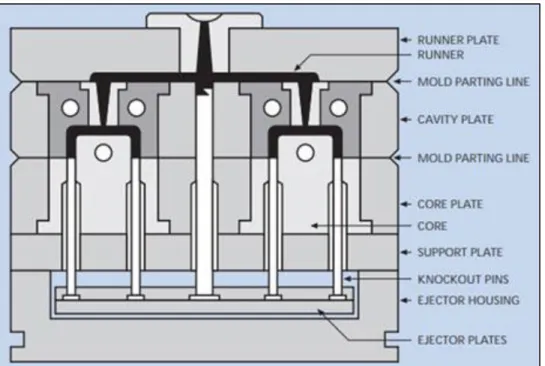
The three - plate mould has double parting line one for the runner and the other for the moulded product. As the runner is separated from the mould output, there is no need of manual separation - Figure 4. Hence, this type of mould will be quite expensive when compared to the two-plate moulding.(6)
Stack mould
The name stack itself indicates that it can have two, three or four levels of injection - Figure 5. The main advantage of using this mould is that, it generally produces a large number of products when compared to two or three-plate moulds by utilizing the same machine clamping tonnage. The only disadvantage of this stack mould is that it needs a large opening to accommodate the mould Height and in the other hand this type of mould is much more expansive when compared to the other two types of moulds and also it tales much longer time to produce and construct the stack. [6]
8 Figure 4-Three Plate Mould(6)
Figure 5-Stack Injection Mould(6)
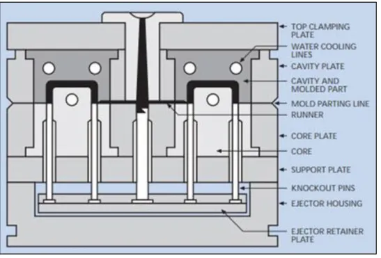
2.2 Parts of injection moulds
Figure 3 and Figure 4 show the basic assembled parts of a plastic injection mould. There are at least 400 parts assembled together so, to represent each and every part the parts of the mould is identified by a technical standard numerical representation for example OR1 indicates O-ring.(7)
The basic parts of mould represented by numerical terms are as follows: • 32- Indicates Locator Ring
• 02-Cavity Plate • 03-Core Plate • 05-Spacer Block • 07- Ejector Plate
• 08- Ejector Pin Retainer Plate • 09- Bottom Clamping Plate • 20- Angle pin
• 30- Knock out Pin • 48- Inter Lock • 320- Jiggle Pin • 480- Pressure Bar • OR- O-Ring • 16- Guide Pin • 580- Cycle Counter
The basic functions and purpose of these injection mould parts are explained below: Fixed clamping plate / top clamping plate
The top clamping plate is used to hold the fixed side of the mould. The fixed side means that one side of the mould is always fixed, and the other side is moveable during ejection process of plastic or it can be said that the plate is attached at the fixed platen of injection machine. Along with this plate the locating ring, eye bolt and the sprue bush are attached.(8)
Runner stripper plate
This plate is used only in 3 plate mould type, the main function of this plate is to cut resin from the nozzle from top of sprue bush and pulls the runner with the help of runner locking pin.(8)
Fixed mould plate / cavity plate
This plate plays an important role among the parts of injection mould. The plate is hollow or in the shape of cavity in which the plastic product is to be obtained. These plates contain
10 supporting components along with it they are, supporting pin, puller bolt and angler pin when slider is attached.(8)
Moveable plate / core plate
This plate plays the same role as that of the fixed mould plate the only difference is that the core plate is not hollow while fixed plate is mostly hollow. So, these plates intersect together while the plastic injection is done. Return pin, leader bush and slider core are the parts attached along with this plate.(8)
Support plate
The main use of the support plate is to support the cavity plate. In the other hand this plate is used because it provides cooling channel during plastic injection and when cavity plate cannot make it. Besides this the plate provides the holes for return pin springs.(8)
Spacer block
The spacer block seems like a rectangle pillar which is mounted in-between the movable clamping plate of the mould (Bottom Plate) and the movable cavity plate. These blocks give space and allows the ejector plate to move when ejecting the part after plastic injection completes. The required length of the spacer block depends up on ejector stoke that are needed to eject product.(8)
Ejector retainer plate
The name itself indicates that the plate is used to retain the ejector pins in proper movement while ejecting the plastic part after injection. It has shoulder bolts and gibes space to ejector leader pin and support pillar.(8)
Ejector plate
This plate is mounted along with the ejector retainer plate and the main function of this plate is that it pushes the ejector pins and the return pins that are connected with the ejector rods.(8)
Bottom clamping plate
This plate belongs to the other end of mould assembly which is the movable side of the mould. This plate serves as the support and provides good guidance to the movable side of the mould that contains support plate, cavity plate and spacer block.(8)
Guide pins and bushes
Guide pins and guide bushes are used to align mould plates and to have a proper sliding of plates during the plastic injection. Varity of standards are available, but every guide pin performs
same task. Use of a light lubricant such as oil containing P.T.F.E. is advised. But, most of the mould makers use grease anyhow it is important to make sure it is greased.
Angle pin
Angle pins are used for the motion of sliding core block and are mostly used in conjunction with a form of core slide retainer. The angle pin is made of DIN 1.7131 steel. The angle pin can also use as straight leader pins. Generally, angle pin is supplied with pre-machined spherical radius on its head to eliminate the grinding process to obtain the perfect angle needed. Use of a light lubricant such as oil contained P.T.F.E is advised during the installation.
2.3 Requirement of mould plate
There are specific requirements of mould plates as because, the plates undergo many tasks such as pressure, heat and load. The basic requirements of mould plate are as follows:
• Good corrosion resistant; • Good machinability; • Easy to clean; • Good heat transfer; • Homogeneity of steel; • Low cost.(9)
2.4 General concept of mould production
In case of plastic injection moulds, a material that withstands high temperature and pressure of plastic is chosen. For example, there are different types of steel verities such as 1018 is a plain carbon steel, 4140 is an alloy steel and 1.2343 is of chromium grade steel which has good mechanical strength at high temperature. So mostly, steels of chromium are preferred for plastic injection mould making.
Initially to produce a plastic product, it is necessary to design a mould for the plastic product in exact dimensions and tolerance. According to the design and dimensions, the steel bars are selected and bought for the production. The steel bars are then cut according to the required parts for the mould. These pars are then taken under different machining process such as drilling, milling, CNC machining, electro discharge machining and surface grinding as per the design that were made for the mould. Most of the drilling process made is to create a path for the coolant to flow in and out over the hot areas of mould. The CNC machining and the milling process is carried
12 out to produce the exact shape of core and cavity parts of mould in order to obtain the shape of plastic required. After all the process the different parts of mould is assembled as a single component that together helps in producing the plastic product output.
2.5 Mould making process involved in the company (10)
Production of mould involves different departments for processing good quality mould and the various process involved in mould making are as follows:
Plan outline Mould Design Material Selection Machining Heat Treatment Core Finishing EDM Assembling Trial
Final Product Output Figure 6- Mould making process
1. Initially the customer need plastic product is analysed and then the designers makes complete cost analysis within two or more working days and presents the plan to manager.
2. The manager analyses the plan and makes changes so that, the plan gets approved for mould making process and the designs begin to design mould using 3D drawing, 3D parting, mould part assembly drawing, EDM drawing, electrode drawing etc.
3. The final approval is then discussed and analysed before the plan moves on to the purchasing segment. The designers then list out personnel opinion to analyse the project according to the information given for the product such as, mould structure, cooling system, runner, slag, venting, etc. According to the design and plan made the type of materials that can be used are then listed and so the raw material for the mould making is ordered.
4. Mould makers verify the raw materials purchased as soon as the material arrived at factory and arrange the different materials with an identification code so that, the technicians understands which material to be machined with suitable tool and cutting speed etc. The technicians should pay attention to the precision of each right-angle side, roughing margin etc.
5. The raw material for the mould undergoes varies machining or production process such as turning, grinding, milling, screw holes, water carrying hole, centre hole and CNC roughing. Then each mould parts are heat treated if necessary.
6. The parts that has got its shape after machining are then heat treated only if there is a need for the material to be heat treated. The mould maker must ensure the hardness and metallurgical analysis. Generally, the hardness will be of 46-50 HRC, for uniform distribution, the hardness differs less than 1HRC.
7. Electrode processing is one of the advance machining processes. There are fine and rough processing. It is very important that it must be sure to pay attention to each processing benchmarks and detect electrode after processing.
8. Before finishing the mould part, it is must to make a right angle for the core part of mould. The vertical degree is less than 0.02mm and finished degree is of 1.6.(10)
9. Here the cutting is nothing, but the pathway provided for the guide bars. Basically, all parts enlarge 0.02mm in case of insert hole and centre hole which
14 can be considered as tolerance clearance. For non-standard thimble, the tolerance clearance will be 0.04mm of the actual size to thimble.(10)
10. The finishing of mould core will be based on the benchmarks after executing right-angle.
11. EDM- it is one of the machining processes carried out for advance machining process. These processes are carried out according to the design drawings. The main purpose of using this machining is to machine, hardened steel eliminating deformation caused by heat treatment. On the other hand, complex dies and moulds can be accurately machined and produced at lower costs. (10)
12. The surface of runner is also to be polished and verified such that the surface does not allow spark or knife pattern to exist.
13. Before assembling the mould, the assembler must make a comprehensive inspection of each and every part to make sure everything is in a good condition. Besides this it is very important to do cleaning and anti-rust treatment.
14. When the mould gets completely assembled with the satisfaction to the assembler, the mould of injection moves for several try-out. Plastic injection is made with the mould and the plastic parts produced out of it is analysed and tested. If any defects or error in the finishing of the plastic found, then the mould is reworked to rectify the defects produced on plastic product.
15. The out is carried out several times such that by 100-150 cycle time, the try-out products tends to be defect free. Then the production department makes production schedule. The technicians track the production process and the feedback is delivered to mould making department.
2.6 Mould colour codes
In the production of mould, the varies parts of the moulds can either be identified with the help of its numerical representation or with the standard colour codes provided from the design sheet. So, there are some standard colour codes used in DGP moulds for easy identification of important parts of the mould from the design drawing which are as follows:
• Purple colour indicates the moulding which is the core and the cavity part of the mould.
• Bluish violet indicates the adjustment parts or the movable parts like angle pin, ejectors etc.,
• Green colour represents the screw thread. • Red colour indicates the zero tolerance H7.
• Violet colour indicates the thread that are made especially for water.
• Greenish blue colour indicates the British standard thread for water (BSPT). • Brown colour indicated the same thread made for water but the only different is
that the standard is NPT.
• Blue colour identifies the path or holes machined for water. • Brownish yellow indicates the oil BSP thread.
• The yellow colour indicated the path for oil in the mould.
Figure 7 shows the clear representation of the colour codes from which the parts of moulds are identified from the design diagram.
16 2.7 Machining
The most common type of machining is milling, which means a material removal process, that performs multitask on a part by cutting away the unwanted material or to obtain the required shape from the material. There are many types of machining process carried out in practice. In such a way, milling is mostly used in practice for producing the parts that are not axially symmetric which includes components that are used in limited quantities, perhaps for prototypes, such as custom design fasteners or brackets. In the other hand milling is used in the fabrication of tooling. For example, three-dimensional moulds are typically milled. Milling is also used as the secondary process as it can perform high tolerance and surface finishing, it is used to mill the parts which are already milled in order to give good surface finish and to obtain the required tolerance.(12)
So, the basic requirement for performing this task is to have a milling machine, workpiece, fixture and cutter. Workpiece is a material that are pre-shaped to fit into the fixtures for milling operation. Here the fixture is nothing but the clamp that are used for holding the workpiece while milling. The cutter is a tool with sharp teeth that are made to rotate at a specified speed. By feeding the tool on to the workpiece with a specified cutting speed, the material is cut away from the workpiece in the form of small chips to obtain the desired shape.
2.8 Cutting parameters
The milling of a workpiece is carried out using the motion of cutting tool towards the workpiece with certain parameters such as cutting speed, speed of rotation of the tool that are estimated according to the type of workpiece material used and the tool size.
There are some of the important parameters taken into consideration while milling which are as follows:
1. Cutting speed – Vc - the cutting speed refers to the speed of the edge of the cutting tool relative to the workpiece during a cut, which are measured in meters per minute (m/min).
2. Spindle speed – N - The speed of rotation of the spindle and the tool attached to the spindle are referred as spindle speed. Rotation per minute (RPM).
3. Cutting feed – Fn - The distance travelled by the cutting tool or the distance travelled by the workpiece for one revolution of the spindle can be referred as cutting feed. This is measured in millimetre (mm) .(13)
4. Feed speed – Va - The travel speed of the tool relative to the workpiece while a cut is made on the workpiece are referred as feed speed. The feed speed is measured
in millimetre per minute (mm/min). The feed speed is the product of feed (mm/rot) and the spindle speed (N).
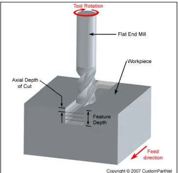
5. Axial depth of cut – Ap - The depth of cut on the workpiece along the tool axis are referred as axial depth of cut - Figure 8. For obtaining a larger axial depth of cut, low cutting speed must be maintained if not, high load can be stressed on to the tool and the tool will reduce its lifetime. Therefore, the workpiece is machined with different cutting speed depending upon the depth of axial cut required.
Figure 8-Axial Depth of Cut(14)
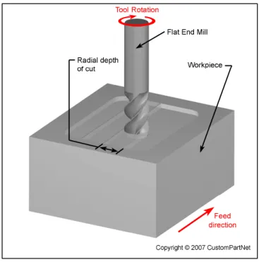
6. Radial depth of cut – Ae - the radius of tool engaged with certain depth of cut on workpiece referred as radial depth of cut.(15) Partial engagement of the tool 70 percentage towards the workpiece is preferable for good condition of the tool while milling. Cutting speed is maintained in order to maintain the tool lifetime and its condition.
2.9 CNC Machining
CNC Machining stands for Computer Numerical Control Machining. It works with the help of computers to control the tools of the machine. Here the tools are nothing, but the machining tool used in process of milling, lathe and grinding. The CNC Machines are not only used for the
18 purpose of metal related machining process, it is also used for the manufacturing of both metal and plastic parts.
There are many advantages of using CNC machining. The process of machining is more accurate than that of the manual machining and it is possible of obtaining the same accurate machining for many parts over repeated machining.(16) As it can perform precision this process are mostly used for the production of complex shapes that are almost impossible to active by the manual machining and are also used in production of three-dimensional complex shapes. So, this is the main reason behind for using the wide range of CNC machines in the machining and manufacturing industries.
The CNC machine does not only perform the machining operations such as milling, and lathe works etc., it also performs different tasks according to the type of CNC used. Some of the examples of CNC machines are as follows: (17)
1. Vertical milling CNC.
2. Lathe that operates with CNC. 3. Plasma cutters.
4. Electric discharge machining EDM. Figure 9 - Radial Depth of Cut (15)
5. Sinker EDM 6. Wire cut EDM.
7. Multi spindle machines or multi axis CNC. 8. Water jet cutter.
The CNC machining plays an important role in mould making industries. It does all the manual machining automatically with the help of programs. There are different kinds of CNC machines that are used for different purpose for example there are CNC machines that only performs lathe activities such as thread, turning, facing, step turning and knurling as it has only rotational axis same as that of lathe, but the only difference is that the machining in CNC is bit faster and does the machining automatically. In the other hand, there are CNC machines which performs milling, grinding operations and they are commonly called as VMC vertical milling machines assisted with numerical programs.(18) These kinds of machines are widely used in the productions and according to the activities performed in milling the CNC machines are of different kinds that varies by the number of axis used. Basically, there are only 3-axis they are X, Y and Z axis.
But as the technology has improved now a day, we have multi axis CNC machines that performs varies machining at the same time. When we look at the machine, it looks like a normal computer operated technique, but the computer’s unique software and control out shows the performance of CNC machining.
Under CNC Machining, the machine tool functions are performed by numerical controls. There are programs which are customized for a workpiece and the programmes are loaded into machines with CNC machining language called G-code and M-code which mainly controls all the activities of machines like the machining cutting speed, speed of the spindle, location of the tool. These codes are very important for the machining operations. These codes are standard codes for many CNC machines. So, learning the codes helps in programming the machine to a correct path of machining the work output.
As the software and the technology developed, now a day it is not necessary to learn all the G-codes and M-codes, because the software itself generates the codes automatically. The only work of the programmer is to create the proper design and set the correct tool and the correct operation that are to be performed in order to obtain the required output.
20 While operating a CNC machine, there are some important things that has to be followed step by step in order to active a good output from the CNC machining operation. Therefore, the step by step operation that are performed while CNC milling are as follows:
Start
Warmup
Program Installation
Workpiece Arrangement
Values Measured for Machining
Fixture offset Z Program Execution Drilling using CNC Verification of Machining Shutdown Figure 10- CNC Operation Start
Before putting the machine to work initially, it is necessary to inspect the level of coolant and the lubricant oil along with the compressed air system for actuating pneumatic components of the machine.
Warmup
The machine is switched on by turning the breaker which is located at the back of the machine. The tool is then checked, and the spindle is made to run for ten minutes as a warmup which may avoid basic faults like over heat of spindle due to sudden start of the machine.
Program Installation
The program sheet is provided by the CNC programmer and the programs are copied to the machine from the network server. Until the programs get downloaded to the machine, the tools given in the program sheet is verified and loaded into the tool carousel. The tool must be ensured that it is good for machining process as because it may have some wear which will not give satisfied machining output. Finally, the length of the tool and the depth in which the tool is going to work is verified.
Work piece Arrangement
The workpiece provided is mounted on the magnetic table by facing correct coordinate as shown in the program sheet. A dial indicator is then clamped into the spindle to verify the workpiece mounted on the table is in the straight position for machining. To set the workpiece straight on the table, the dial indicator is set to zero on one end of the workpiece and when the indicator is moved on to the other end of the workpiece, it must indicate the same zero if not, it means that the work piece is not straight. So, the workpiece is adjusted to zero on both the ends of it. With this condition to hold the workpiece tight enough for machining, the table is magnetised so that, it provides good clamping during machining and avoids movements and improper machining.
Values Measured for Machining
The movement of the axis X, Y, Z from the program depends on the dimensional value measured from the Centrepoint of the workpiece. For example, if a rectangular workpiece is to be machined along its horizontal length X-axis, in its length out of value ten the centre point lies on the value five. So, to make the machine understand the distance for machining, the value must be programmed by giving negative value of 5 to positive value of five along X- axis. Hence the program is written by measuring the dimensions from the centre point of the workpiece. Therefore,
22 it is necessary to set the value of coordinates X, Y, Z to zero (midpoint of the workpiece) on the machine.(20)
To obtain the centre point for a rectangular workpiece in general, the dimensions of the rectangular workpiece is measured along X and Y axis with the help of dial indicator. The total length along X and Y axis is divided by its half and the value obtained is enrolled along the respective X and Y axis.
There are different ways of calculating centre point according to the type of workpiece presented for the machining. There are basically 3 types of workpiece presented they are the parts having holes on its corners, the parts that are box or rectangular in shape and has no holes on its corners and the parts that are irregular in shape.
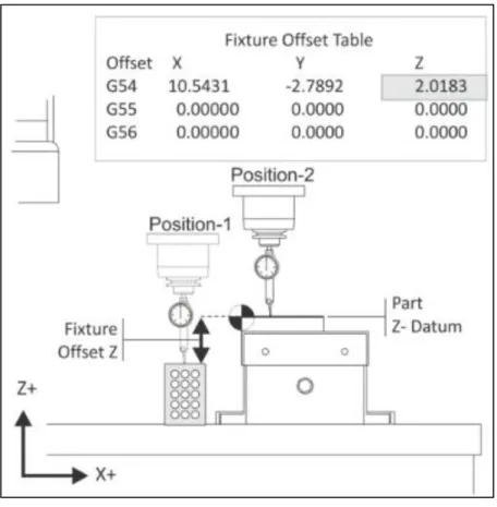
Fixture offset Z
In case of Z axis, the tool length is measured with the help of touch probe and the respective tool is set to zero on the top layer of the work piece as shown in Figure 11.
Figure 11-Z-axis Offset(19) Program Execution
The tool length listed in the program sheet is verified and the respective program is made to run for machining.
Drilling using CNC
There are simple programs that can be written using M and G codes directly on the machine for drilling. But, mostly now a day it is also pre-programmed, and the program is copied to the machine and made to run. When using different drill bits of different lengths and diameters, it is very important to measure the length of the tool and verify by Z offset value using touch probe.
Verification of machining
The machined surface and the depth of milling is verified using Vernier calliper and the screw gauge if any unfinished milling or targeted depth are not obtained, then the tool condition is verified in case of bad surface finish and to obtain the targeted depth the value of Z axis is adjected respectively.
Shut down
The tools are removed from the spindle, the work area is cleaned, and the machine is switched off properly. It is very important to clean the work area and leave the tools and the other measuring instruments in its respective place where it belongs.
2.9.2 CNC Milling machines IN DGP
There are two CNC machines used which is of same type 3-axis vertical milling CNC. The only difference between the two machines are the distance of motion of 3-axis. The machines are:
DOOSAN
• The maximum distance in which the axis can able to perform machining in DOOSAN DNM750II are X- 1630mm, Y- 762mm, and Z- 650mm.
• The maximum speed of the spindle can reach up to 12000rpm. • The tool rack is vertical spin type.
MICRON VCP 600
• The maximum distance in which the axis can able to perform machining in MICRON VCP 600 are X- 600mm, Y- 450mm, and Z- 450mm.
• The maximum speed of rotation can be up to 18000rpm. • The tool rack is horizontal spin type.
24 2.9.3 Manual programming
As the software and the technology developed, now a day it is not necessary to learn all the G-codes and M-codes, because the software itself generates the codes automatically. The only work of the programmer is to create the proper design and set the correct tool and the correct operation that are to be performed in order to obtain the required output.
Some of the parameters are involved for generating the manual programming in CNC. For example, to manually program the machine for machining a circular pocket, there are some of the standard parameters involved - Table 1. An illustration of some of those codes can be found on
Figure 12.
CODE VALUES OPERATIONS
Q215 0 MACHINING OPERATION
Q223 60 CIRCULAR DIAMETER
Q368 0.2 ALLOWANCE FOR SIDE
Q207 500 CUTTING SPEED FOR MILLING
Q351 +1 CLIMB OR UP-CUT
Q201 -20 DEPTH
Q202 5 PLUNGING DEPTH
Q369 0.1 ALLOWANCE FOR FLOOR
Q206 150 CUTTING SPEED FOR PLUNGING
Q338 5 INFEED FOR FINISHING
Q200 2 SET-UP CLEARANCE
Q203 +0 SURFACE COORDINATE
Q204 50 2ND SET-UP CLEARANCE
Q370 1 TOOL PATH OVERLAP
Q366 1 PLUNGE
Q385 500 CUTTING SPEED FOR FINISHING
Figure 12-Circular Pocket(21)
2.9.4 Surface finish in CNC machined parts(22)
There are different parameters and procedures taken into account in order to get a perfect finishing of the surface on the parts that are machined through CNC machine. Basically, to obtain a good result in machining process the dimensions and tolerances, shape, quality of the raw materials will be taken into account. But, apart from that there is something that need to be worked on after the machined parts are produced. The following are the steps that are to be considered to obtain a good surface finish.
Measuring surface finish
The best way to measure the surface finish of the machined part is via microscope or through the profile projector. By understanding the micro structure of the machined part, on comparing the one or more machined parts operated on different parameters it will be easy to choose a correct parameter for machining to obtain a good surface finish.
Cutting speed and feed
The very important parameter that has to be taken in account in order to active a good surface finish is the cutting speed and the feed. To obtain a good surface finish the cutting speed must be
26 high, and the feed must be always maintained lower. So, the correct speed of rotation and the feed has to be selected according to the type of material use and the relative tool.
Chip breakers
Chip breaker is a piece of metal clamped to the rack surface of the tool which bends the chip and breaks it down in order to avoid the larger chip profile. But nowadays there is no need of attaching a separate metal for breaking the chip instead, there are other geometry of tools available and are called inserts. So, the inserts have the geometry to break the continuous chip flow. If the chip flow has very larger profile, then it affects the surface finish of the material as there are possibilities of removal of extra material form the surface than expected. So, breaking of chip at the right time has to take place in order to improve the surface finish of the material(22).
Tool condition
It is very important to inspect the condition of the tool before starting every machining process. If the tool is found little bit wear, then it is not possible to active the good surface finish. In the other hand it will be difficult to active the required accurate dimension after machining.
Balance of tools
It is very important to use balanced tooling technique to reduce the apparent vibration during the finishing process. This step gets even more essential if the RMP is set to high.
Insert geometry
Generally, to obtain a good surface finish of the material, it is the basic necessary to have sharp inserts, having positive lead angle and rake angle.
Runout
A high amount of runout also makes the way for resulting in bad surface finish. It causes the improper function for the tool, by making it spin in an eccentric path instead of spinning in the desired circle. So, it is always better to switch tools with a better and lower run out, like an ER collet chuck for setscrew-style end mill holder which is noticed to produce lower runout than the latter.
Roughing and finishing operations
Using the same tool for both roughing and finishing will result in loss of tool life as well as loss to active the surface finish of the material. The tool used for roughing are operated in different parameters and can be used for different axial depth of cut, in case of the tool used for finishing, the speed of rotation must be always higher than that of the feed and has very low axial depth of cut.
Dwells and pauses
Unnecessary dwells and pauses are also a hindrance for a proper finishing work. If the tool stopes when in contact with the workpiece it gives a mark on the workpiece that are to be surface finished. So, it is necessary to change the process altogether, insuring that the tool does not stopes in-between again. So, this parameter should also be considered for obtaining the good finishing of the workpiece.
Cutting down the centre line
The best way to ensure a proper cutting process is to follow a 70:30 ratio rather than going for a full on 50:50 method. Cutting down at the centre will probably slap the insert along the edge and may cause burning. This may lead into improper surface finish.(22)
2.10 Milling Workflow
Initially a CAD diagram is created (either 2D or 3D), using a design software that is convenient for the product to be produced. These CAD diagrams are opened in the software that is connected to the CNC machine for example Power Mill is one of the software used for generating the codes for machining.(16)
As soon as the CAD diagram is imported into the milling software, the software automatically generates a basic code for the machine programming such that, it automatically finds the midpoint of the CAD design and predicts the distance and dimensions of the design diagram. So, it is easy for the programmer to set the machining distance, dept of machining from the mid-point of the part.
The programmer now selects the preferred tool and the other parameters of machining like setting the cutting speed, speed of the spindle, depth of milling, diameter and sets M-codes and saves the activity. These activities are then exported as the program by the software automatically and are then imported to the CNC machine as a program in which the machine can understand. So, these are the basic operation in which the metal part is machined under the control of CNC Machining.
2.11 Milling time
The time needed for completing the milling process depends upon the initial setup time and the cycle time required for the type of workpiece presented for milling process. The initial step time includes the arrangement of the fixtures, setting the machine axis and the tool for the correct path of milling to be obtained. The cycle time includes the amount of time required for milling the
28 part or the workpiece presented. Apart from this the cycle time can be divided into following four types:
Load/Unload time - The time take to load the workpiece into the milling machine which includes the time taken for proper clamping of the workpiece as the same the time taken for unloading the workpiece after the milling process.
Cut time - The time taken for the tool to make the necessary milling operations on the workpiece.
Idle time - This is also referred as non-productive time. The time required for making the correction in-between the milling process is called as idle time. For example, if any of the tool is Brocken while milling then the machine must be stopped, and the required tool has to be replaced in order to continue the milling operation.
Tool replacement time – The time taken for replacing the tool that has expired its life time, can be referred as the tool replacement time.(23)
2.12 Milling standards
National and international standards are used for the purpose to standardize the defections, environmental requirements, and test methods used for milling, the way of selecting the standards depends up on the requirement between the supplier and the user. In case of united states, ASME has developed the standards B5.45-1972 for milling cutters and end mills.(24)
General tolerance includes: +/- .127mm for local tolerance, it is +/- .254mm in case of plastic with variation depending up on the seize of the part, 0.762mm minimum wall thickness for material, and 1.524mm minimum wall thickness for plastic.
2.13 Workpiece materials
The workpiece that are kept for milling is obtained from the raw material stock. The raw material stock is cut down into desired shape and size so that, the workpiece can fit into the fixtures and kept comfortable for milling operations. These raw material stocks are available in different shapes such as, flat sheets, solid bar (rectangular, cylindrical, hexagon, etc.), hollow tubes (rectangular, cylindrical, etc.), and shaped beams (I-beams, L-beams, T-beams, etc.). in some case parts such as casting, or forging are also used.
Milling can be performed in certain suitable material and some types of typical plastics. Basic types of materials in which the milling is usually carried out are as follows: (25)
• Aluminium • Brass • Magnesium • Nickel • Steel • Thermoset plastic • Titanium • Zinc
While selecting a material for milling, several parameters and factors are taken into consideration which includes, the cost, resistance to wear, and machinability. In case of machinability it is difficult to quantify, but can be said to possess the following characteristics:
• Results in a good surface finishing. • Provides longer tool life.
• Requires low force and power for milling. • Provides easy collection of chips.
2.14 Possible defects in milling
Most of the defects occurs due to the inaccurate parameters of tool and conditions. Some of the common defects occurs due to the following reasons:
• Incorrect cutting parameter – The cutting parameters such as cutting speed, spindle speed, and the axial depth if cut must be adjusted as per the condition of the tool and the material of the workpiece presented. To active a good finishing, the speed of the spindle must me always greater than that of the feed rete of the machine tool. If any of this parameter differs then the machining process results in damage of tool, burn mark on the workpiece, and inaccurate depth of cut due to the damage of the cutting tool.(26)
• Improper cutting tool – As the tools are used again and again for the machining operations, the tools are to be verified for its condition as there are possibilities of the cutting tool to be worn out. So, the use of wear tool can damage the workpiece
30 as well as the machining condition by providing the result of inaccurate axial depth of cut.
• Improper arrangement of workpiece – The workpiece kept for milling operations must have a proper clamping, so that there is no movement of the workpiece while machining operation. In case of improper clamping of the workpiece there is a high possibility of workpiece movement from its correct position. So, this may result in damage of both tool and the workpiece, vibration during machining, loss in obtaining the required machined workpiece output.(26)
3 CASE STUDY
The study is fully based on the performance of the cutting tool used in milling. Mainly, the performance of the tool depends on the cutting parameters used and the amount of wear occurred after milling. As the cutting tool gets under wear, the tolerance and the standard of milling goes out of determined value. Hence, to improve the quality of milling the performance of the tool must be improved by decreasing the tool wear.
3.1 Tool wear
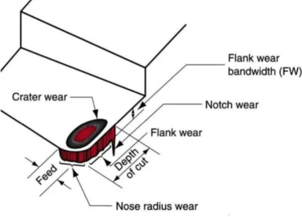
According to Author Debapriya. M , the tool wear can be defined as “The change of shape of the tool from its original shape, during cutting, resulting from the gradual loss of tool material” (27). There are different types of tool wear which are as follows:
• Flank wear - Flank wear of tool refers to the wear taken place on side cutting edge of the tool flank - .(27)
• Crater wear - the wear that occurs on tool which is in contact with chips which means the rake face of the tool gets wear.(27)
• Edge wear - Alhadeff, L L Marshall, M B Curtis and D T Slatter, T says that, the wear taking place on the cutting face of the tool can be called as edge wear. This type of wear occurs due to the operation of tool under high speed.(28)
32 3.2 Causes of tool wear
There are certain reasons which are in direct cause of tool wear. In such a way, by using air or coolant supply on tool will provide lubrication and cools down the heat generated between the tool and the workpiece. On the other hand, the effect of tool wear includes:
• Increased cutting force. • Increased cutting temperature. • Not enough coolant supply. • Poor surface machining.
3.3 Performance of cutting tools in milling
Milling plays a very important role in mould production (29). So, it is always important to bear in mind to maintain a good standard of milling operations. The quality of mould lies on the quality of milling operations performed in mould production. The standard of milling process can be evaluated by measuring the quality of machined surface and the tool wear rate.
To obtain a good surface finishing by milling, the tool wear rate and the condition of the tool must be maintained. Hence, by measuring the activities of the tool, it will be easier to improve the performance of the cutting tool as well as the quality of milling operation which in turn improves the quality of mould production (30).
As a result, the performance of the cutting tool is mainly focused in order to improve the quality of milling operation and the tool life. Therefore, to improve the tool life, the rate of tool wear has to be controlled.(31) The tool wear basically occurs due to the friction in between the cutting tool and the material which is cut. But apart from these, there are different parameters which are to be taken into account in order to reduce the tool wear they are:
• The cutting speed. • Axial depth of cut.
• Radial depth of cutting tool. • Spindle speed.
• Type of materials presented for milling. • The period of milling operation.
3.4 Conditions maintained to have proper tool life
The speed of rotation and the cutting speed play a very important role in both milling and tool life. Hence in case of heat treated material or headend material, lower level of spindle speed is maintained.
In case of soft material or for the smaller diameter cut that are performed manually, the speed of rotation can be maintained higher.
In the other hand the cutting speed, it is inversely proportional to the condition maintained for the speed of rotation. For example, the material that has higher hardness or of abrasive material the cutting speed is maintained higher so that the cutting is made easier. For the material that has soft material, low or suitable cutting speed can be maintained.
3.5 Reason and remedy for tool damage
Problem Instance of problem Solution
Tool break
At start or end of cut
Use short tool.
Prefer lower cutting speed. Reduce over hanging.
During cutting
Check tool for wear and replace the tool sooner.
Check the tool holder condition. Check the coolant flow and condition. Changing direction Use circular interpolation if possible. Heavy tool wear
Use lower speed of rotation. Check the coolant flow. Use high cutting speed
Poor surface finish
Good surface finish but rough. Use lower cutting speed. Check coolant.
Excessive cut marks. Use higher speed. Use lower cutting speed.
Chip welding Check coolant flow
Poor accuracy Not perpendicular. Undersize.
Use conventional machining. Use smaller radial depth of cut. High speed.
Lower cutting speed.
Chattering Use climb milling.
34 3.6 Milling tool design
There are different varieties of milling tools used for various cutting operation of the material. But the selection of the cutting tool is not easy because, it depends on various factors such as the cost, tool life, quality of the tool material, type of operations performed, and the material presented for the milling operation. So, depending up on all these factors the correct milling tools are selected and presented for the operation.(33)
The most common milling operation performed is End Milling. The tool for which the performance calculated here will be of end mill tool type. An end mill is nothing but milling the workpiece peripheral or making slot cuts on it, which are determined by the step-over distance across the workpiece in order to machine the given feature such as profile, slot, pocket and complex surface contour. There is certain formula in which the end mill tools are designed because, the end mill tools have its cutting teeth on it one end as well as on its sides which is more or less similar to a drilling tool. The various design properties that indicates the eligibility of end milling tool are as follows:
• Shape: Mostly the shape of the end mill will be circular and has a flat bottom cutting edge. Apart from this there are different shapes of cutting edges used to obtain different machining operations like pocket milling, circular pocket etc, • Flutes/ Teeth: The flutes are the helical grooves running up the cutter, while the
sharp blade along the edge are known as the tooth. The necessity of the flute is very important because when the tooth performs cutting operation at the same time the flute helps to pull the chips of the material due to the rotation of the cutter. The milling cutter has one to many teeth of which 2, 3 and 4 are most common. Typically, the tool with more amount of teeth will result in rapid material removal rate.(34) In this case, a 4-tooth can remove material twice the rate of 2-tooth cutter. • Helix angle: The helix angle is nothing, but the angle of flute provided to make cutting easier. If there are no angle given for the flute, entire tooth will be in contact with that of the workpiece which will result in vibration, bad surface finishing, and bad accuracy. Hence the helix angle is very much important for the faster and smooth cutting operation. In order to obtain a smooth surface finishing, the tool with a greater helix angle will be chosen(35).
• Coatings: Coating the tool helps in improving the surface finish, and the tool life while the tool works under high speed and cutting area. Generally polycrystalline diamond (PCD) is considered as one of the hard coating used on cutters which must withstand high abrasive wear. The coated tool will have 100 times longer life time
than that of the uncoated tool but, the only disadvantage of coating is that the tool cannot be presented for milling at temperatures above 600-degree C.(36) In case of aluminium, it has the capability of sticking to the teeth of the tool under machining which may result in welding of material by itself. Hence for machining aluminium at certain temperature, a special coating is made of TiAIN which helps in preventing the self-welding of the material and also allowing the tool to finish its operation for a longer period.
• Shank: The cylindrical part of the tool which is provided to hold and locate the tool into the tool holder is known as shank. The shank must be perfectly round and capable of holding the tool by friction. The diameter varies according to the standard size of the tool provided.
3.7 Tool provided for experiment
The tool provided is capable for milling high hardened material which are suitable for dry cutting. As the tool is coated by a layer called Nano grain carbide (NG), it has high wear resistance. The tool can also be used for obtaining excellent surface finishing by operating the tool at high speed.(37) The design of the tool is very suitable for deep slotting.
The specification of the tool says that the tool is coated with Nano grain carbide material (NG) which is in blue colour hence, this tool is specifically called as pulsar blue. The blue colour decoration may wear out quickly which looks not uniform coated but, this will not affect the performance of the tool.
The dimension of the tool says that the tool has overall length (L2) of 100mm, milling diameter (d1) is of 8mm, shank diameter (d2) of 8mm, length of cut (L1) is of 12mm, effective length (L3) is of 25mm, corner radius (r) is of 0.5mm and the neck diameter (d3) is of 7.7mm - Figure 14.
The cutting parameters of the tool says that the tool can move in three different directions they are towards horizontal, vertical and cross which are similar to three dimensional (3D) directions. The number of flutes provided are 4 which can result in good material removal rate. The tool has a standard helix angle of 30 degrees which results in faster cutting. The tolerance calculated from the milling diameter lies between 0 to 0.015mm and the tolerance calculated from the corner radius lies more or less 0.015mm. Finally, the shape of the shank is of plain circular designed in such a way that the tool obtains good clamping to the tool holder for good surface milling operation.
36 Figure 14 - End mill geometry(32)
3.8 Workpiece and experimental setup
The main task of the experiment is to find the good operating parameter of the given tool which helps in improving the life time of tool and better milling. Hence, measurements are concentrated on the wear on tool by operating the tool under two scenarios they are, operating the tool according to the parameters provided by manufacturer and according to the normal parameters followed by the operator.
The parameters differ according to the workpiece provided for milling. Hence before milling, it is very important to know the type of material provided and the general properties of the material. In this the workpiece provided is of steel 1.2343 is a chromium-molybdenum-vanadium alloyed hot work tool steel. It has good mechanical strength at high temperature as well as has high tempering resistance combined with good machinability and polish ability and has good toughness and ductility.
The main application of the steel 1.2343 include: mould making, tools for aluminium extrusion, die holders and extrusion dies. It is also used for the applications such as sliders, forging stamps for circular cutting etc,
Heat treatment plays an important role in the steel 1.2343 as because, the mechanical and the physical properties gets optimized. Hence, the parameters for milling operations are chosen according to the range of heat treatment capabilities of the material.
3.9 Operating parameters given by the manufacturer:
Figure 15 - Parameters by manufacturer(38)
Figure 15 shows the operating parameter of the tool provided by the manufacturer for the experiment and the value of (Ap) axial depth and the radial depth (Ae) while milling is considered 8 mm. As the tool number indicates 101750 and diameter 8mm for hardness 40-50 the parameters from manufacturer are chosen as listed below: [38]
• Vc- 195 m/min • Va- 1085 mm/min • Fz- 0.035 mm • N- 7760 rpm • Fn- 0.14 mm
3.10 Parameters followed by the operator
Besides the manufacturer’s parameter, there are some standard parameter fixed or changed for the comfort of milling tolerance to be reached. while machining, the values of (Ap) axial depth and the radial depth (Ae) are the same as used for manufacturer parameter 8 mm. In this way, there are parameters followed by the operator while machining are as follows:
• Vc- 200 m/min • Va- 1250 mm/min • Fz- 0.039 mm
38 • N- 8000 rpm
• Fn- 0.156 mm
3.11 Experimental setup
The workpiece is of material 1.2343 steel which has the dimension of 74mm length, 44mm of breath and thickness - Figure 16. The given material is clamped with the help of clamping unit provided to hold the workpiece suitable for machining. This whole setup is mounted on a magnetic table of the 3-axis vertical CNC milling machine. The magnetic table is magnetized which tightly holds the clamping unit from movement caused while machining the workpiece.
Figure 16 - Workpiece
The measurements of the tool and the workpiece dimensions are calculated and loaded to the machine for milling. Before starting the process, the workpiece is checked for its initial alignment that suits machining operations. With this setup the milling is started on for 0.1mm increment and the wear rate of the tool is calculated by operating the machine according to the parameters provided by manufacturer and by the operator itself.
Figure 17 shows the initial arrangement for milling the work piece. Initially, before placing the work piece on the magnetic table, the table is cleaned and inspected for no chips left out on table. Secondly, the clamp that holds the work piece is place on to the magnetic table. In this condition the clamp is verified and checked for alignment and confirmed that it remains straight. To hold this clamp tightly on table, the magnetic table is magnetised which holds the clamp tightly on to the table.
The workpiece is then clamped, and the centre point and the milling values are measured and loaded on to the machine for milling operation.
Figure 17 - Experimental setup
3.12 Experimental output
The wear of tool is measured in two different operating parameters. But the operation carried over milling is the same. Here the given tool is made to create hole of 16 mm diameter, for every 8mm of depth the tool is inspected having 0.1mm as increment and the finishing of the workpiece is also checked. In this way the result of experiment is calculated.
OPERATOR PARAMETERS
Experiment
number Depth (mm) Surface finish
Tool wear condition wear 1. 8 There is no difference noticed on the tool and no wear occurred. 2. 16 There is a slight white mark found on the flutes it is nothing but the coating of Nano grain carbide (NG) is worn out but
40 still the tool has
no wear
3. 24
The tool remains in the same condition. But could still fine more changes on coating. 4. 32 A slight wear can be noticed 5. 40 Tool wear occurred Total 40
Table 3 - Evaluation of operator parameter MANUFACTURER PARAMETERS Experiment number Depth (mm) Surface finish Tool wear condition wear 1. 8 No tool wear noticed.
2. 16 Has difference in tool coating 3. 24 No wear can be noticed 4. 32 A slight wear is noticeable. 5. 40 Slight Tool wear can be noticed. Total 40
Table 4 - Evaluation of manufacturer parameter
3.13 Result
Parameters Total Depth Machined (mm) Scale Measured (µm) Average Wear Rate Measured (µm) Result Manufacturer Parameter 40 100 50-60 Better tool
performance but can
achieve only
moderate surface finish.
42 Operator
parameter
40 100 80-90 Better surface finish
but not suitable to have proper tool life. Table 5- Result
Figure 18 shows the wear observed on microscope, captured and measured according to the manufacturer parameter. The wear rate is measured with the scale of 100 micro meter and the average tool wear length of the four-flute obtained is of 50 to 60m
Figure 18 - Microscopic result of the tool (manufacturer parameter)
Figure 19 shows the wear observed on microscope, captured and measured according to the operator parameter. The wear rate is measured with the scale of 100m and the average tool wear length of the four-flute obtained is 80 to 90m.
Figure 19 - Microscopic result of the tool (operator parameter)
As the result of experimenting the tool in both operator and manufacturer condition, the wear found on the tool is high on operating the tool under operator’s parameter this is because the feed per tooth (Fz) or chip load is 0.039 mm while the manufacturer’s feed per tooth provided is 0.035 mm. The chip load plays a very important role in performance of the tool as it controls the required force to cut the work material and directly affects the metal removal rate and the surface finish. The feed per tooth is directly proportional to the tool wear rate. As the feed per tooth increases the amount of wear occurred on tool will also be high. Therefore, it is always important to operate the tool under suitable results of lower feed per tooth. In case of manufacturer parameter, the cutting speed maintained is of 195 m/min and has the feed per tooth of 0.035mm which resulted in tool wear of 50-60m. On the other hand, the operator’s parameter maintains the cutting speed of 200 m/min and has feed per tooth of 0.039 mm that resulted in tool wear of 80-90m. As the resulted values from both parameters does not have a greater difference, both the parameters have an advantage and disadvantage towards milling. To have a better tool life and a moderate surface finish it is always to maintain the parameters according to the manufacturer which also helps in less production cost. In the other hand to have a good surface finishing out of milling it is better to choose the operator parameter as because it helps in improving production time.