On the Machinability and Surface Finish of Superalloy GH909 Under Dry Cutting Conditions
Ming Luoa* , Haizhen Lia
Received: December 12, 2017; Revised: February 27, 2018; Accepted: April 15, 2018
GH 909 alloy is a kind of low thermal expansion superalloy with high strength and low
expansion coefficient. It is mainly used for manufacturing of aero-engine turbine casings, sealing ring, vanes and other gap control parts, to improve the working efficiency and thrust of the engine as well as to reduce gas loss and fuel consumption. However, the machinability is still a problem that restricts the application of GH909. This paper investigated the machinability referring to cutting forces, surface quality and tool wear in the milling process with carbide tool. The main conclusions are: (1) GH909 has similar machinability with other Nickel-based alloys, cutting velocity does not have great influence on cutting forces for small radial cutting depth. (2) Good machined surface quality can be get for cutting velocity around 70m/min. (3) To get good tool performance and reduce tool wear rate, cutting velocity can be set to no larger than 80m/min.
Keywords: machinability, surface finish, cutting force, tool wear, superalloy.
*e-mail: [email protected]
1. Introduction
GH 909 alloy is Fe-Ni-Co-based low thermal
expansion superalloy, it has high strength, low expansion coefficient, almost constant modulus of elasticity under
temperature below 650ºC. GH909 alloy is mainly used for manufacturing of aero-engine turbine casings, sealing ring, vanes and other gap control parts. The application
of GH909 alloy can improve the working efficiency and thrust of the engine, and can reduce gas loss as well
as fuel consumption. While used for manufacturing of aero-engine parts, machining of these parts either by turning or by milling is required. However, the published research is mainly about machining of Ni-based alloy 718, the machinability of alloy 909 is rarely studied.
Motivated by the above analysis and requirements, the
machinability of alloy 909 is studied in this paper. The machinability of materials refers to the ease with
which a metal can be machined permitting the removal
with satisfactory finish at low cost. The machinability of
superalloys is not only related with material property, but
also affected by the machining condition. For superalloys such as GH909 and In718, their machinability is low, it means they are difficult to cut. Machinability of Nickel-based alloys has been studied, such as Inconel
718 1,2, GH2132 3 and so on. However, seldom research
has been focused on the machinability of superalloy GH909, it leads to the confusion of selection proper
cutting parameters for machining process. Like other Nickel-based alloys, GH909 is difficult to cut, the
cutting force and temperature are very high during the machining process, resulting in fast tool wear and poor
surface finish.
Cutting force is one of the main factors that reflect
the ease of metal cutting, lots of research has been done
to investigate the effects of cutting parameters on cutting
forces 4,5. While machining Inconel 718, Choudhury and
El-Baradie 6 found that the cutting forces did not decrease
because of higher shear stress. Experiments conducted by Devillez et al. 7 showed that cutting forces in wet and
dry turning of Inconel 718 were almost the same and the cutting force was a bit lower at cutting speed of 60m/min. In side milling of Inconel 718, Liao et al. 8 found that
cutting force did not change a lot within the cutting speed
20-120m/min, while it showed increase for cutting speed larger than 120m/min. Nalbant et al. 9 studied the effect
of cutting speed on cutting forces in milling of Inconel 718 with ceramic cutting tools, they found an
increment-decrement relationship between cutting speed and cutting
force within 150-250m/min. While machining Inconel alloy 738, Davoodi and Tazehkandi 10 found that the depth of
cut has the most effective on cutting forces, followed by
feed rate and cutting speed, and increasing cutting speed at permitted range caused softening and elastic deformation in cutting region and resulted in reduction of cutting
forces. They also found the increase of cutting force when the cutting speed is larger than a certain value. From the
existing research results it can be found that cutting forces do notchange a lot with increase of cutting speed within certain range, while the cutting speed is much larger, the cutting forces show an increment with increase of cutting
speed. Among all the machining parameters, cutting depth has the most effective on cutting forces.
Tool wear is one of the main concern in the
machining process, it affects the dimension accuracy 11,
machined surface integrity 12, and machining stability
13. Choudhury and El-Baradie 6 found that cutting speed
has more effect than cutting depth and feed rate on tool
life. While machining Inconel 718 with ceramic cutting
tools, research shows that the main tool wear mechanism are crater, tool breakage, and notch wear 9. Sikdar's 14
research showed that different wear mechanism occurred for ceramic tools under various cutting conditions and
micro chipping occurred at high feed rates. Henderson et al. 15 investigated the cutting forces in milling of
Nickel-based superalloys, their experimental results indicated that the cutting speed has a significant influence on the
amplitude of forces and tool wear rate. Li et al. 16 studied
the end milling of Inconel 718 using coated carbide
inserts under dry cutting conditions, their experiments showed that significant flank wear was the predominant
failure mode. Krain et al. 17 conducted experiments
on milling of Inconel 718TM and results showed that
increase of immersion ratio resulted in reduction of tool life due to increased cutting length, abrasion rates,
thermal and mechanical loads. Yao et al. 18 found that
the use of different cutter orientations have significant effects on the tool life, workpiece surface integrity and
surface morphology. Hao et al. 19 analyzed the tool
wear morphology and mechanism in dry machining of
Inconel 718, and they found that adhesion and lamellar
wear caused tool wear at low cutting speed 20m/min, while the element diffusion between tool and workpiece and oxidation reaction all accelerate the formation and
peeling of wear debris. While turning N-155
iron-nickel-base superalloy, Davoodi and Eskandari 20 found that
cutting speed was the most significant factor and the
most dominant tool failure modes were adhesion wear. During dry machining of Inconel 825, Thakur et al. 21
et al. found the dominating tool wear mechanism were abrasion, adhesion, and diffusion wears. Zhu et al. 22
concluded that the actual wear rate is the combination of adhesion, abrasion, diffusion, and oxidation wear
rate in cutting of Nickel-based alloy, depending on the temperature and stress distributions. However, tool wear
mechanism for the machining of GH909 is still unclear
and lack of investigation.
Surface finish reflects the machined surface quality
23, it will influence the component service life. Both
cutting parameters and cutter geometry 24 will affect
the final machined surface finish. Furthermore, tool
wear in the machining process will have great influence
on the machined surface finish. Sonawane and Joshi 25
investigated the effect of machining parameters on the
machined surface quality in a single-pass of a ball-end
milling cutter, and results showed that the maximum surface roughness is observed near the tool tip region
on the machined surface. Sikdar's 14 research showed
that the quality of the machined surface was better at high cutting speeds than that at low speed, under which condition the surface was full of short grooves with high
feed rate. In turning of Inconel 718, Devillez et al. 7 found
that the cutting speed of 60m/min in dry condition with coated tool can get globally optimized surface finish
quality. Davoodi and Tazehkandi 10 found that the most
effective parameter on surface roughness was feed rate, and higher cutting speed with lower feed rates can be used for getting lower surface roughness in machining
of Inconel 738. Tazehkandi et al. 26 recommended the
cutting speed should not exceed 80m/min while machining
Inconel 725 to avoid deterioration of surface finish,
and there was a general trend of increasing of cutting
forces as feed rate and cutting depth increase. Current
research show that higher cutting speed with low feed
rate can get good surface finish for machining of Nickel-based alloy. Choudhury and El-Baradie 6 recommended
the cutting speed for machining Inconel 718 using the carbide inserts should be within 20-25m/min. Krain et al. 17 indicated that while milling Inconel 718TM, the
immersion ratio can be set as 50% and the chip thickness
of 0.1mm. Liao et al 8 suggested that cutting speed of
90-110m/min is appropriate for slot milling of Inconel 718 and 55-135 m/min for side milling.
Notwithstanding the aforementioned various studies proposed therein, none of them studied the machinability
of GH909 alloy. Therefore, this paper investigated the
machinability referring to cutting forces, surface quality
and tool wear in the milling process with carbide tool.
Finally, the recommended cutting parameters for milling
GH909 alloy are given based on the machinability analysis.
2. Experiments
2.1 Material
The chemical composition (wt%) of the GH909 alloy is shown in Table 1, the containing of Niobium and Titanium components are used for precipitation
hardening, the silicon addition results in improved notch
rupture and tensile properties. Some physicalproperties of GH909 are listed in Table 2. The rigidity and the
modulus of elasticity of GH909 alloy remains nearly
constant over a wide temperature range. Due to its low
expansion andconstant elastic modulus, GH909 alloy
has highly resistant to thermal fatigueand thermal shock.
Table 1. Chemical composition of the alloy GH909.
C Mn Si Ni Co Al Ti Nb Cr B Cu P S Y Fe
2.2 Experimental setup
The experimental were carried out on a four-axis machining center YHVT 850Z, the cutting tool used for
cutting forces and roughness investigation is coated carbide
milling cutter with four flutes and its diameter is 10mm, and the diameter for tool wear investigation is 12mm. Three groups of experiments were conducted: cutting
with large radial depth, cutting with large axial depth
and tool wear experiments. The cutting experiments are given from Table 3 to Table 5. Two machining processes: end milling and flank milling, are commonly used in the workshop. The cutting experiments with large radial cutting
depth simulates the end milling process, and the cutting experiments with large axial cutting depth simulates the
flank milling process. The milling experiment setup is shown in Figure 1, the stock length is 120mm. Referring to machining of hard-to-cut materials, radial depth of cut is usually set to small value, such as below 1.0mm,
Table 2. .Physical properties of alloy GH909.
Density (g/cm3) Melting range (ºC) W5(%) j (%)
8.19 1400 16 47
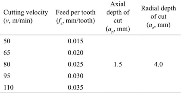
Table 3. Cutting experiments with large radial depth.
Cutting velocity (v, m/min)
Feed per tooth (fz, mm/tooth)
Axial depth of
cut (ap, mm)
Radial depth of cut (ae, mm)
50 0.015
1.5 4.0
65 0.020
80 0.025
95 0.030
110 0.035
Table 4. Cutting experiments with large axial depth.
Cutting velocity (v, m/min)
Feed per tooth (fz, mm/tooth)
Axial depth of cut (ap, mm)
Radial depth of cut
(ae, mm)
50 0.020
6.0 0.5
70 0.035
90 0.050
110 0.065
Figure 1. Milling experimental setup.
to avoid large cutting force or high cutting temperature
2.3 Measurement
Cutting force, tool wear and surface finish are the key indexes for machinability evaluation. In this study,
cutting forces during the milling process were measured
by the Kistler 9123C dynamometer, cutting forces along radial, tangential and axial directions were recorded. Tool
wear and machined surface roughness were measured
by the Alicona G4 3D micro coordinate measurement machine, and the measured scope range is 200µm*200µm.
3. Results and Discussion
3.1 Cutting force
Regarding milling with large radial cutting depth and low axial cutting depth, variation of resultant cutting force with cutting velocity and feed per tooth is shown
in Figure 2. With the increase of feed per tooth, cutting force shows increasing trend. As for the influence of
cutting velocity, the cutting force shows increase trend for cutting velocity smaller than 80m/min, but there is a decrease after 80m/min for feed per tooth larger than
0.02mm/tooth. Results for large axial cutting depth and small radial cutting depth are shown in Figure 3. For Nickel-based alloys like Inconel 718, research results
show that the cutting forces do not show obvious change with the increase of cutting velocity within a certain
range. In this research, the same trend is found for
small radial cutting depth while there is a discrepancy for large radial cutting depth with different feed per
tooth. For feed per tooth smaller than 0.02 mm/tooth,
the trend is almost the same, but for those larger than
0.025 mm/tooth, cutting forces shows increase trend for cutting velocity smaller than 80m/min. For milling
process with large axial cutting depth and small radial cutting depth, the cutting forces show slow increase
trend with cutting velocity. Comparing forces with large
radial cutting depth, cutting forces show an interesting dramatic increase with cutting velocity under large feed per tooth, while this phenomenon is not observed under
the situation with small radial cutting depth.
Although the feed per tooth is set to much larger value for large axial cutting experiments, the maximum actual undeformed chip thickness is almost the same as that for large radial cutting experiments, it is smaller than the value of feed
per tooth, as shown in Figure 4. For example, the maximum actual undeformed chip thickness is about 0.028mm for feed per tooth at 0.065mm/tooth. For both groups of experiments, it
can be found that for the same cutting velocity, the large axial cutting depth approach can achieve the same material removal rate (MRR) with much larger feed per tooth,while the cutting
force is almost the same. Take the cutting velocity at 65m/min
of large radial cutting depth as example, the cutting force for
feed per tooth at 0.025mm/min is about 390N. Meanwhile,
for large axial cutting depth with cutting velocity as 70m/
min, the cutting force for feed per tooth at 0.050mm/tooth is about 400N. However, for large axial cutting depth and small radial cutting depth, the heating duration for each cutter flute
is much shorter than large radial cutting depth situation, which
means the working condition is much better for the cutter.
Table 5. Cutting parameters for tool wear experiments.
No. velocityCutting (v, m/min)
Feed per tooth (fz, mm/tooth)
Axial depth of cut (ap, mm)
Radial depth of cut (ae, mm)
1 50 0.025
1.5 4.0
2 50 0.035
3 80 0.015
4 80 0.025
5 80 0.035
6 110 0.015
7 110 0.025
8 110 0.035
Figure 2. Resultant cutting force with large radial cutting depth
and low axial cutting depth
Figure 3. Resultant cutting force with large axial cutting depth and small radial cutting depth
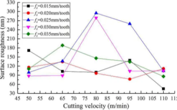
3.2 Surface quality
For large radial cutting depth and small axial cutting depth, the influence of cutting velocity and feed per tooth
on surface roughness is shown in Figure 5. There is no
general trend of the surface roughness, but for some of them the surface roughness value reduces gradually with
the cutting velocity. With the increase of feed per tooth, the main tendency is increase of the surface roughness.
period, which is the period between two neighboring chips breakage, does not show relevance with the cutting
velocity. However, cutting length within one chip breakage period shows increase with the feed per tooth. As shown
in Figure 7(a), the cutting length within one chip breakage
period is about 70µm for feed per tooth of 0.020mm/tooth, while it is about 138µm for feed per tooth of 0.035mm/ tooth and 195µm for feed per tooth of 0.05mm/tooth. In the milling process, the path of the cutter edge tip is
trochoid, the larger the feed, the greater the maximum
radius of the trochoid. For small radius, the deformed
chip tends to be compressed from both the rake face of
the cutter and the cross-feed direction. For large radius,
especially for straight cutting like orthogonal cutting, thedeformed chip is mainly compressed on the rake face
of the cutter. Therefore, it reveals the influence of feed per tooth on chip breakage. Cross the chip breakage
area, the surface roughness shows obvious variation,
as shown in Figure 8.
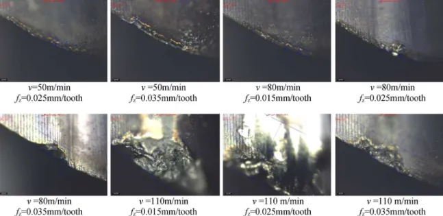
3.3 Tool wear
Tool wear under different cutting conditions for the same type of milling cutter is shown in Figure 9. The
low thermal conductivity of the GH909 alloy and the work hardening in the milling process cause elevated high temperature at the interface between the cutter and
the workpiece. High temperature accelerates the welding
and adhesion onto the cutting tool, which leads to the
damage on the tool rake face. Besides, the adhesion
and work hardening during the milling process lead to severe notching between the cutting edge and the
machined surface, and induce flank wear. Due to the
above reasons, the cutting edge is almost completely
worn out. This phenomenon is obvious for cutting velocity less than 80m/min. For cutting velocity larger
than 80m/min, chipping is observed as the main tool wear
mode. As was explained in section 3.1, cutting forces
increase slowly with the increase of cutting velocity, larger cutting forces accelerate the damage of cutting
edge. For the cutting velocity of 80m/min, cutter edge chipping is also observed for feed per tooth of 0.035mm/ tooth. From the above analysis, it can be concluded that
for milling of GH909 alloy, the cutting velocity below
80m/min will have better tool performance.
4. Conclusions
In summary, GH909 alloy shows similar machinability as other Nickel-based alloys, such as In718. Based on
the analysis of the results, conclusions can be drawn as follows for milling of GH909 alloy with carbide tools:
Figure 5. Influence of cutting velocity and feed per tooth on surface
roughness for large radial cutting depth
For large axial cutting depth and small radial cutting
depth, the surface roughness shows interesting similarity. The surface roughness value is low at cutting velocity of
70m/min for all feeds per tooth, while it is high at cutting
velocity of 90m/min. As for feed per tooth, larger value
will not result inhigher surface roughness value, as shown
in Figure 6.
Figure 6. Influence of cutting velocity and feed per tooth on surface
roughness for large axial cutting depth
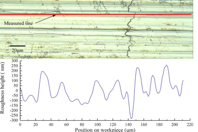
The sampled surface texture is shown in Figure 7,
the surface roughness is formed by the bottom edge of
the milling cutter. From the surface texture, the chip
breakage marks are obviously shown for feed per tooth
1. Cutting force shows increasing trend with the increase of feed per tooth. For small radial cutting
depth, cutting forces do not show obvious change
with the increase of cutting velocity.
Figure 7. Machined surface texture
Figure 8. Surface roughness
2. Within the experimental parameter range, the surface
roughness value is low at cutting velocity of 70m/
4. Wan M, Ma YC, Feng J, Zhang WH. Study of static and dynamic ploughing mechanisms by establishing generalized model with static milling forces. International Journal of Mechanical Sciences. 2016;114:120-131.
5. Sui S, Li Y, Shao W, Feng P. Tool path generation and optimization method for pocket flank milling of aircraft structural parts based on the constraints of cutting force and dynamic characteristics of machine tools. The International Journal of Advanced Manufacturing Technology. 2015;85(5-8):1553-1564.
6. Choudhury IA, El-Baradie MA. Machining nickel base superalloys: Inconel 718. Journal of Engineering Manufacture. 1998;212(3):195-206.
7. Devillez A, Le Coz G, Dominiak S, Dudzinski D. Dry machining of Inconel 718, workpiece surface integrity. Journal of Materials Processing Technology. 2011;211(10):1590-1598.
8. Liao YS, Lin HM, Wang JH. Behaviors of end milling Inconel 718 superalloy by cemented carbide tools. Journal of Materials Processing Technology. 2008;201(1-3):460-465.
9. Nalbant M, Altin A, Gökkaya H. The effect of cutting speed and cutting tool geometry on machinability properties of nickel-base Inconel 718 super alloys. Materials & Design. 2007;28(4):1334-1338.
10. Davoodi B, Hosseini Tazehkandi A. Cutting forces and surface roughness in wet machining of Inconel alloy 738 with coated carbide tool. Proceedings of the Institution of Mechanical Engineers, Part B: Journal of Engineering Manufacture. 2014;230(2):215-226.
11. Luo M, Wang J, Wu B, Zhang D. Effects of cutting parameters on tool insert wear in end milling of titanium alloy Ti6Al4V.
Chinese Journal of Mechanical Engineering. 2017;30(1):53-59. 12. Stipkovic MA, Bordinassi EC, Farias A, Delijaicov S. Surface
Integrity Analysis in Machining of Hardened AISI 4140 Steel.
Materials Research. 2017;20(2):387-394. tooth results in longer chip breakage period, cutting
velocity does not show clear relevance with chip
breakage period.
3. To get better tool performance in milling of GH909
alloy, the cutting velocity should be set smaller
than 80m/min.
4. In summary, the cutting velocity for milling of
GH909 can be set to around 70m/min and no larger than 80m/min, and small radial cutting depth can be used to get good cutter working
condition. For further research, surface integrity in milling of GH909 can be investigated to fulfil the requirements of components service performance.
5. Acknowledgments
This work was co-supported by the National Natural Science Foundation of China (51675438) and the Fundamental Research Funds for the Central Universities (No. 3102017gx06008).
6. References
1. Arunachalam R, Mannan MA. Machinability of nickel-based high temperature alloys. Machining Science and Technology. 2000;4(1):127-168.
2. Luo M, Luo H, Zhang D, Tang K. Improving tool life in multi-axis milling of Ni-based superalloy with ball-end cutter based on the active cutting edge shift strategy. Journal of Materials Processing Technology. 2018;252:105-115.
3. Wang X, Huang C, Zou B, Liu H, Zhu H, Wang J. A new method to evaluate the machinability of difficult-to-cut materials. The International Journal of Advanced Manufacturing Technology. 2014;75(1-4):91-96.
13. Yao Q, Luo M, Zhang D, Wu B. Identification of cutting force coefficients in machining process considering cutter vibration.
Mechanical Systems and Signal Processing. 2018;103:39-59. 14. Sikdar SK. Machinability of nickel based superalloys with
carbide and ceramic tools in milling. [Dissertation]. Montreal: Concordia University; 2007.
15. Henderson AJ, Bunget C, Kurfess TR. Cutting force modeling when milling nickel-base superalloys. In: Proceedings of the ASME 2010 International Manufacturing Science and Engineering Conference; 2010 Oct 12-15; Erie, PA, USA. p. 193-202.
16. Li HZ, Zeng H, Chen XQ. An experimental study of tool wear and cutting force variation in the end milling of Inconel 718 with coated carbide inserts. Journal of Materials Processing Technology. 2006;180(1-3):296-304.
17. Krain HR, Sharman ARC, Ridgway K. Optimisation of tool life and productivity when end milling Inconel 718TM. Journal of Materials Processing Technology. 2007;189(1-3):153-161. 18. Yao C, Tan L, Yang P, Zhang D. Effects of tool orientation
and surface curvature on surface integrity in ball end milling of TC17. International Journal of Advanced Manufacturing Technology. 2018;94(5-8):1699-1710.
19. Hao Z, Gao D, Fan Y, Han R. New observations on tool wear mechanism in dry machining Inconel 718. International Journal of Machine Tools and Manufacture. 2011;51(12):973-979.
20. Davoodi B, Eskandari B. Tool wear mechanisms and multi-response optimization of tool life and volume of material removed in turning of N-155 iron-nickel-base superalloy using RSM. Measurement. 2015;68:286-294.
21. Thakur A, Gangopadhyay S, Mohanty A. Investigation on Some Machinability Aspects of Inconel 825 During Dry Turning.
Materials and Manufacturing Processes. 2015;30(8):1026-1034. 22. Zhu D, Zhang X, Ding H. Tool wear characteristics in machining
of nickel-based superalloys. International Journal of Machine Tools and Manufacture. 2013;64:60-77.
23. Gaitonde VN, Karnik SR, Maciel CHA, Rubio JCC, Abrão AM. Machinability Evaluation in Hard Milling of AISI D2 Steel. Materials Research. 2016;19(2):360-369.
24. Shi Z, Li Y, Liu Z, Qiao Y. Determination of minimum uncut chip thickness during micro-end milling Inconel 718 with acoustic emission signals and FEM simulation. International Journal of Advanced Manufacturing Technology. 2017. DOI: 10.1007/s00170-017-0324-z.
25. Sonawane HA, Joshi SS. Analysis of machined surface quality in a single-pass of ball-end milling on Inconel 718. Journal of Manufacturing Processes. 2012;14(3):257-268.