Nageswara Rao Damera
Andhra University Dept of Mechanical Engineering Visakhapatnam, India
Vamsi Krishna Pasam
[email protected] GITAM University Dept of Industrial Production Engg Visakhapatnam, India
Performance Profiling of Boric Acid
as Lubricant in Machining
Turning is a widely used metal removal process in manufacturing industry that involves generation of high cutting forces and temperature. Lubrication becomes critical to minimize the effects of these forces and temperature on cutting tool and workpiece. The conventional cutting fluids employed in machining have certain limitations with regard to their use for ecological and economic reasons. Development of lubricants that are eco friendly is acquiring importance. In this context, application of solid lubricants has proved to be a feasible alternative to the conventional cutting fluids. In the present work, Boric Acid is used as a lubricant in turning process. Variations in cutting force, tool wear, tool temperature and surface roughness are studied under different machining conditions. The results indicate that there is considerable improvement in the machining performance with Boric Acid assisted machining compared to dry and wet machining.
Keywords: turning, solid lubricant, boric acid
Introduction
1
Reduction of environmental pollution has been the main concern in the present day manufacturing industry. Increasing pollution-preventing initiatives globally and consumer focus on environmentally conscious products has put increased pressure on industries to minimize the use of cutting fluids (Tan et al., 2002). It is reported (Sreejith; Ngoi, 2000) that cutting fluids can pose serious problems, the major ones being those related to preservation of the environment, workers’ health, etc. However, the use of lubricant cannot be swayed away in view of the high temperatures and forces generated during machining. The heat generated in machining adversely affects the quality of the products. As an alternative to the conventional cutting fluids, researchers experimented with biodegradable and cryogenic coolants (Brinksmeier et al., 1992) (Inasaki et al., 1993), in order to reduce the heat generated in machining zone by reducing the coefficient of friction and tool wear. The effectiveness of cryogenic coolant seemed to increase at higher feeds. It reduced the magnitude of tensile residual stress for all materials, although to varying degrees, under all feed levels. This was attributed to the efficient cooling action, better modes of chip formation, less specific energy and finally, lower grinding zone temperature (Paul; Chattopadhay, 1996). The concept of minimum quantity lubrication (MQL) was also employed as an alternative approach. A study has been carried out in the area of eco-friendly sustainable manufacturing using clean machining processes utilizing
minimum quantity of lubricant such as MoS2 powder and grease
based graphite mixed with water and SAE 20 oil in various proportions instead of flooding coolant (Bagchi et al., 1972) (Lathkar; Basu, 2000). Advances in modern tribology have identified several solid lubricants, which are promising for sustaining and providing lubricity over a wide range of temperatures. Most of these lubricants, which include graphite, molybdenum disulphide, tungsten disulphide and calcium fluoride, belong to a special class of materials known as lamellar solids. Researchers (Venugopal; Venkateswara Rao, 2004) investigated the use of graphite as a lubricating medium while grinding SiC to reduce the heat generated in the grinding zone. The tangential force component and hence, the specific energy requirement is found to be considerably reduced using graphite as a solid lubricant. The effective role of graphite as lubricant was evident from the overall improvement in the process. Researchers (Shaji; Radhakrishnan, 2003) investigated the possibility of using graphite as a lubricating medium to reduce the heat generated in the grinding zone in surface
grinding. Different process parameters like cutting forces, temperature, specific energy and surface roughness are observed and reported to be reduced when compared to those in grinding with conventional coolant. In another study, it is shown (Deng Jianhua et al., 2005) that the friction coefficient at the tool-chip interface in dry
cutting of hardened steel and cast iron with Al2O3/TiC/CaF2 ceramic
tool was reduced compared to that of Al2O3/TiC tool without CaF2
solid lubricant.
Boric Acid (H3BO3) is one of the most popular solid lubricants
and has excellent lubrication properties without calling for expensive disposal techniques. The most important characteristics of boric acid for use as a lubricant are that it is readily available and environmentally safe. The Environmental Protection Agency has established that boric acid is benign and the Clean Water Act does not classify it as a pollutant. Several studies related to the lubrication properties of boric acid are carried out over the past several decades (Peterson et al., 1960) (Johnson; Sliney, 1962) (Erdemir, 1991) (Erdemir et al., 1991) (Erdemir et al., 1997) (Erdemir et al., 1999). These works have primarily focused on the performance of boric acid in high temperature applications. The studies indicated that boric acid’s unique layered inter-crystalline structure makes it a very promising solid lubricant material because of its relatively high load carrying capacity and low steady state friction coefficient (0.02). Another study focused on the use of boric acid as a lubricant in manufacturing processes such as forming and drilling. In metal forming applications (Erdemir, 2008) (Wei et al., 2000) (Rao; Wei, 2001), it is shown that boric acid provided very low friction between an aluminium workpiece and a steel forming tool. During these processes, the post-fabrication cleaning of boric acid was environmentally safe, non-toxic and water-soluble. In an earlier work by (Liang; Jahanmir, 1995), drilling experiments with sapphire tools indicated that the addition of boric acid to distilled water increased the rate of drilling of polycrystalline alumina by a factor of two. In addition, boric acid was found to help in reducing friction and corrosion when mixed with cutting and grinding fluids (Branneen et al., 1990) (Rekow et al., 1993) during machining processes. It is very important to note, however, that the success of boric acid in each of the above studies was dependent on the continuous replenishment of boric acid into the contact region.
In the present work, Boric Acid is used as solid lubricant during turning of EN8 steel using HSS and carbide cutting tools. Tool wear, Cutting forces, Cutting temperatures and surface roughness were measured during machining. Cutting tests carried out under
dry andwet conditions were compared with those carried out with
Experimental Work
Number of variables affects the machining performance, the important parameters being the cutting conditions, tool geometry and type of lubricant. In this study lubricating condition is selected for experimental condition. Experiments are conducted under dry, wet and solid lubricant conditions to study the cutting forces, tool wear, tool temperature and surface roughness in turning. The experimental details are presented in Table 1. Cutting velocity and feed rates are selected based on the tool manufacturer’s recommendations for workpiece material and tool combination (HMT, 1998).
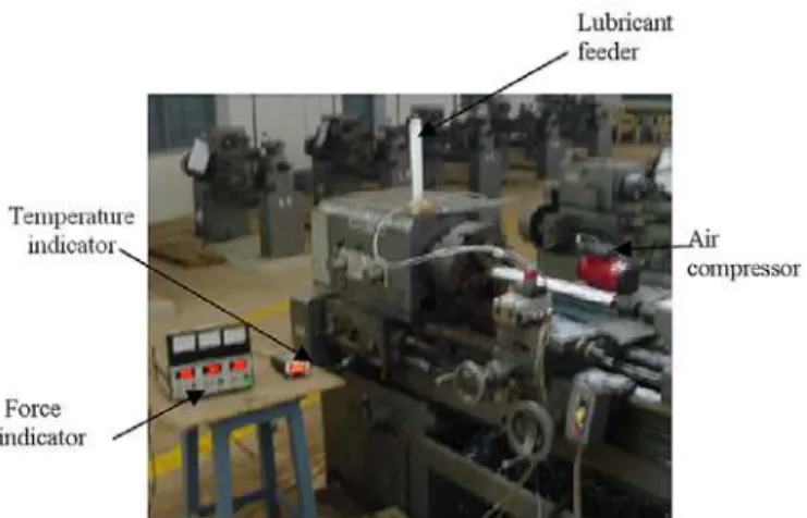
The cutting forces are measured with calibrated strain gauge dynamometer. The tool wear is measured off-line at the end of each cut under 30 x enhanced. The temperature is sensed by the embedded thermocouple (Venkatesh; (Chandrasekaran, 1982) (Srinivasa Rao et al., 2006). A thermocouple is placed at the bottom of the tool insert in the tool holder as shown in Fig. 1. The temperature measured by the thermocouple is only a representative figure for comparison purpose as this does not measure the cutting zone temperature. Calibration of the thermocouple is carried out in a
water bath with a thermometer and a maximum of 2oC difference is
noted over a range from 40oC to 95oC. Talysurf is employed for
measuring average surface roughness (Ra).
Figure 1. Tool holder with provision for thermocouple.
Flood coolant is applied at the rate of 0.11 m3/min. The
experimental setup developed for machining with solid lubricant powder is shown in Fig. 2. The solid lubricant powder is fed to a container attached to the tool post of the machine as shown in Fig. 3. The outlet of the container is connected to one end of a T-joint pipe while other end is facilitated with a convergent nozzle used for the flow of compressed air as shown in Fig. 4. Compressed air while passing through the nozzle creates low pressure at the T junction that sucks the powder along with self weight of the powder and allows it to flow freely through the other end. The outlet of T junction is arranged in such a way to ensure that solid lubricant powder flows continuously to the machining zone. After ensuring the setup for proper flow experiments are conducted in triplicate. Average of the results is considered and taken as the final value to compensate for the discrepancies in the process, if any. For economic viability, trial is done at low mass flow rates. The entire machining operation using solid lubricant powder is carried out in a closed chamber so that powder particles are not allowed to mix freely in air. A solid lubricant powder recovery system is used to reduce waste. This system contains a sieve to separate solid
lubricant powder from chips produced during machining process.
Finally, a magnetic separator is used to separate fine metal particles from solid lubricant powder. This system allows the powder to be reused.
Figure 2. Experimental setup showing the powder feeder.
Figure 3. Powder feeder attached to tool post.
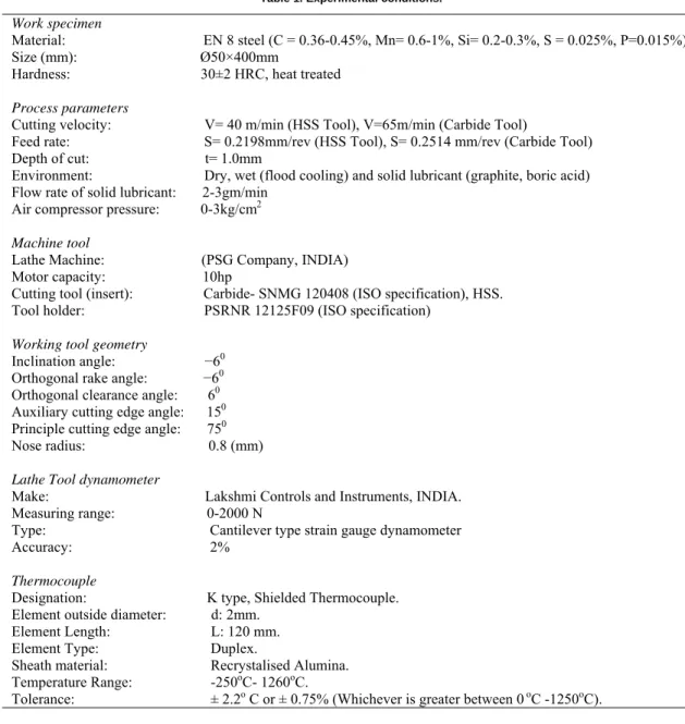
Table 1. Experimental conditions.
Work specimen
Material: EN 8 steel (C = 0.36-0.45%, Mn= 0.6-1%, Si= 0.2-0.3%, S = 0.025%, P=0.015%) Size (mm): Ø50×400mm
Hardness: 30±2 HRC, heat treated
Process parameters
Cutting velocity: V= 40 m/min (HSS Tool), V=65m/min (Carbide Tool)
Feed rate: S= 0.2198mm/rev (HSS Tool), S= 0.2514 mm/rev (Carbide Tool)
Depth of cut: t=1.0mm
Environment: Dry, wet (flood cooling) and solid lubricant (graphite, boric acid) Flow rate of solid lubricant: 2-3gm/min
Air compressor pressure: 0-3kg/cm2
Machine tool
Lathe Machine: (PSG Company, INDIA) Motor capacity: 10hp
Cutting tool (insert): Carbide- SNMG 120408 (ISO specification), HSS. Tool holder: PSRNR 12125F09 (ISO specification)
Working tool geometry
Inclination angle: −60
Orthogonal rake angle: −60
Orthogonal clearance angle: 60
Auxiliary cutting edge angle: 150
Principle cutting edge angle: 750
Nose radius: 0.8 (mm)
Lathe Tool dynamometer
Make: Lakshmi Controls and Instruments, INDIA.
Measuring range: 0-2000 N
Type: Cantilever type strain gauge dynamometer Accuracy: 2%
Thermocouple
Designation: K type, Shielded Thermocouple.
Element outside diameter: d: 2mm. Element Length: L: 120 mm.
Element Type: Duplex.
Sheath material: Recrystalised Alumina.
Temperature Range: -250oC- 1260oC.
Tolerance: ± 2.2o C or ± 0.75% (Whichever is greater between 0 oC -1250oC).
Results and Discussion
A comparative performance analysis of the solid lubricant application with dry and wet machining is done. Fig. 5 and Fig. 6 show the variation of main cutting force and longitudinal feed force with cutting time while machining under three different conditions for a period of 30min each. Results show that the cutting force is considerably less with application of solid lubricant compared to dry and wet machining. The lubricant effectiveness in minimizing the frictional affects at the tool and workpiece interaction in case of solid lubricant assisted machining is evident from the reduced cutting forces compared to that of dry and wet machining.
2 0 0 3 0 0 4 0 0 50 0 6 0 0 70 0 8 0 0 9 0 0
0 10 20 30 40
Machining T ime, mins
M
a
in
C
u
tt
in
g
F
o
rc
e
,
N Dry-HSS
Cutting Fluid-HSS
Boric Acid-HSS
Dry-Carbide
Cutting Fluid-Carbide
Boric Acid-Carbide
Figure 5. Variation of main cutting force with machining time.
50 100 150 200 250
0 10 20 30 40
Machining Time, mins
L
ongi
tudi
na
l F
e
ed
F
or
c
e
,
N
Dry-HSS
Cutting Fluid-HSS
Boric Acid-HSS
Dry-Carbide
Cutting Fluid-Carbide
Boric Acid-Carbide
Figure 6. Variation of longitudinal feed force with machining time.
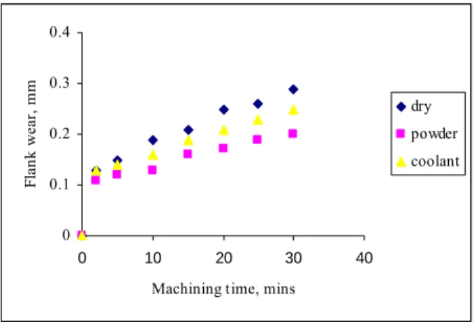
Figure 7 and Fig. 8 show a comparison of flank wear while machining in the three different conditions. Flank wear is observed to be considerably less in Boric Acid assisted machining for both the tool-work combinations. During cutting process the chip slides against the tool rake face at a high speed, and induces high cutting temperature. The effectiveness of the solid lubricant in any context is strongly affected by temperature, pressure, speed and environmental conditions; in the present case, cutting temperatures, cutting forces, cutting conditions and ambience. Under such high cutting temperature, the solid lubricant may melt and smear creating a thin lubricating film on the rake face of the tool. The substantial reduction of flank wear observed is due to the low coefficient of friction and sliding action. Low shear resistance within the contact interface is also one of the reasons for reduction of flank wear. Three important properties of the solid lubricant i.e. low friction coefficient, sliding between layers and low shear resistance are due to its lamellar structure only. Hence, lubricating action of this lamellar solid mainly depends on cutting conditions and tool-work combinations.
0 0.1 0.2 0.3 0.4 0.5
0 10 20 30 40
Machining time, mins
F
la
n
k
w
ea
r,
m
m
dry
powder
coolant
Figure 7. Variation of flank wear with machining time (HSS tool).
0 0.1 0.2 0.3 0.4
0 10 20 30 40
Machining time, mins
F
la
n
k
w
e
a
r,
m
m
dry
powder
coolant
Figure 8. Variation of flank wear with machining time (Carbide tool).
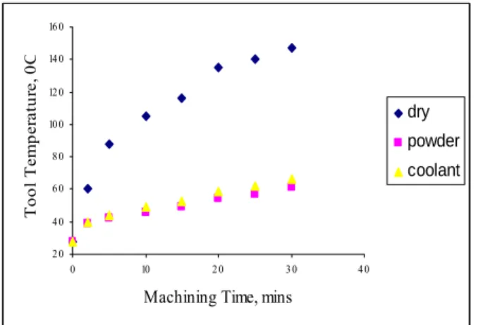
Figure 9 and Fig. 10 compare tool temperature measured at nodal point against cutting time for all the three cases. Temperature is lower in case of Boric Acid assisted machining compared to dry machining. The result is implied by the low coefficient of friction as
Boric Acid dehydrates above 1700C and softens at about 4000C. The
2 0 4 0 6 0 8 0 10 0 12 0
0 10 2 0 3 0 4 0
Machining T ime, mins
T
ool
T
e
m
p
e
ra
tur
e,
0
C
dry
pow der
coolant
Figure 9. Variation of tool temperature with machining time (HSS tool).
2 0 4 0 6 0 8 0 10 0 12 0 14 0 16 0
0 10 2 0 3 0 4 0
Machining Time, mins
T
o
o
l T
e
m
p
e
ra
tu
re
, 0
C
dry
powder
coolant
Figure 10. Variation of tool temperature with machining time (Carbide tool).
Variation of cutting force with flank wear in Boric Acid assisted machining is shown in Fig. 11 and Fig. 12. Cutting force increases with flank wear both in HSS and carbide tools. This may be attributed to increase in temperature with machining time, which leads to flank wear thus requiring higher specific energy and cutting force for material removal. Though the value of flank wear is different in both cases, the trend of cutting force variation with flank wear is the same. As tool wear is less in case of boric acid assisted machining compared to dry and wet machining, cutting forces tend to be lower with boric acid as lubricant.
Figure 13 and Fig. 14 compare surface roughness of the machined surface in the three conditions. The results indicate better surface finish with Boric acid, while machining with either of the tools, demonstrating its effectiveness. This could be due to the reduction in the cutting forces. The decrease in surface roughness due to boric acid can be attributed due to the inherent lubricating properties even at high temperatures. The lubricating action of the Boric Acid reduces the frictional forces at the tool, workpiece and chip interface. This decreases the temperatures at the cutting zone and results in lesser tool wear, thus resulting in surface quality improvement.
2 0 0 3 0 0 4 0 0 50 0 6 0 0 70 0 8 0 0 9 0 0
0 0 .1 0 .2 0 .3 0 .4
Flank Wear, mm
M
a
in
C
u
tt
in
g
F
o
rc
e
, N
HSS
Carbide
Figure 11. Variation of main cutting force with flank wear (boric acid).
50 10 0 150 2 0 0 2 50
0 0 .1 0 .2 0 .3 0 .4
Flank Wear, mm
L
o
ngi
tudi
na
l F
e
e
d F
or
c
e
,
N
HSS
Carbide
Figure 12. Variation of longitudinal feed force with flank wear (boric acid).
0 1 2 3 4 5
dry cutting fluid boric acid
S
u
rf
ac
e r
oug
hne
ss
R
a,
m
ic
ron
s
Series1
0 1 2 3 4 5
dry cutting fluid boric acid
S
u
rf
a
c
e
r
oughne
ss
R
a
, m
ic
ron
s
Series1
Figure14. Surface Roughness (Ra) for different lubricants (Carbide Tool).
Conclusions
In the present work cutting forces, tool wear, tool temperature and surface roughness of workpiece during machining under the lubricating action of Boric Acid are compared with dry and wet machining. The experimental results reveal that the use of Boric Acid solid lubricant is advantageous over dry and wet machining.
i Boric Acid improved the process performance by reducing the
cutting forces and tool wear. This is because of the formation of a boric acid film on the surfaces is lubricious and functioned due to its layered crystal structure and unique bond characteristics.
ii Better surface finish is achieved with the application of Boric Acid compared to dry machining and machining with conventional cutting fluids. The mechanism responsible is explained as low coefficient of friction at the tool workpiece interface with the formation of lubricating film.
iii Solid lubricants like Boric Acid do not possess a pathogenic clinical history. They are relatively free from hazards inherent with the use of conventional cutting fluids.
iv The results clearly demonstrate the suitability of Boric Acid as a lubricant in metal cutting.
References
Bagchi, H.; Mukharjee, N.P.; Basu, S.K., 1972, “Investigation of metal cutting using molybdenum disulphide as a cutting fluid”, Industrial Lubrication and Tribology, pp: 239-243.
Branneen, W.T.; Burt, B.D.; Mc Donald, R.A., 1990, “Phosphite amine lubricant for metal working and machining”, US Patent No.4, pp: 965-1002.
Brinksmeier, E.; Heinzel, C.; Wittmann, M., 1992, “Friction, cooling and lubrication in grinding”, Annals of the CIRP, Vol. 48 (2), pp:155 - 163.
Deng Jianhua, Cao Tongkun, Yang Xuefeng, Lin Jianhua, 2005, “Self-lubrication of sintered ceramic tools with CaF2 additions in dry cutting”,
International Journal of Machine Tools and Manufacture, Vol. 45, pp: 1-7.
Erdemir, A., 1991, “Tribological properties of boric acid and boric-acid-forming surfaces: part I, crystal chemistry and mechanism of self-lubrication of boric acid”, Lubr. Eng. Vol. 47, pp: 168-178.
Erdemir, A., 2008, “Synergistic effects of liquid and boric acid solid lubricant films on friction and wear of sliding steel surfaces”, Tribology Section, Materials and Components Technology Division, Argonne National Lab. In: http://www.luboron.com/pdf/SynergisticEffects.pdf
Erdemir, A.; Eryilmaz, O.L.; Fenske, G.R., 1999, “Self-replenishing solid lubricant films on boron carbide”, Surf. Eng, Vol. 15(4), pp:291-295.
Erdemir, A.; Fenske, G.R.; Erck, R.A.; Nicholas, F.A.; Bush, D.E., 1991, “Tribological properties of boric acid and boric- acid-forming surfaces. Part II, mechanisms of formation and self-lubrication films on boron and boric oxide-containing surfaces”, Lubr. Eng, Vol. 47, 179-183.
Erdemir, A.; Halter, M.; Fenske, G.R., 1997, “Preparation of ultra low-friction surface films on vanadium diboride”, Wear, Vol. 205, pp:236-239.
HMT - Hindustan Machine Tools, 1998 “Production Technology”, Tata Mc Graw Hill Publishing company, New Delhi.
Inasaki , I.; Toenshoff, H.K.; Howes, T.D., 1993, “Abrasive machining in the future”, Annals of the CIRP, Vol.42 (2), pp: 723-732.
Johnson, R.L.; Sliney, H.B., 1962, “Ceramic surface films for lubrication at temperatures of 20000F”, Ceram. Bull., Vol. 41, pp: 504-508.
Lathkar, G.S.; Basu, S.K., 2000, “Clean metal cutting process using solid lubricants”, Proc. 19th AIMTDR Conf., IIT Madras, Narosa pub., pp:15-31.
Liang, H.; Jahanmir, S., 1995 “Boric Acid as additive for core-drilling of alumina”, Journal of Tribology, Vol. 117, pp: 65-71.
Paul, S.; Chattopadhay, A.B., 1996, “Effects of cryogenic cooling on grinding forces”, International Journal of Machine Tools and Manufacture, Vol. 36, pp: 63-72.
Peterson, M.B.; Murray, S.L.; Florek, J.J., 1960, “Consideration of lubricants for temperatures above 10000F”, ASME Transactions, Vol. 2, pp:
225-234.
Rao, K.P.; Wei, J.J., 2001, “Perfomance of a new dry lubricant in the forming of aluminium alloy sheets”, Wear, Vol. 249, pp: 86-93.
Rekow, E.D.; Zhang, G.M.; Thompson, V.P.; Jahanmir, S., 1993, “Factorial design technique to investigate the effect of machine tool parameters and machining environment on surface finish”, J. Dent. Res. IADR 570.
Shaji, S.; Radhakrishnan, V., 2003, “An investigation on solid lubricant moulded grinding wheels”, International Journal of Machine tools and Manufacture, Vol. 43, pp: 965-972.
Sreejith, P.S.; Ngoi, B.K.A., 2000, “Dry machining: of the future”, Journal of Material Processing Technology, Vol. 101, pp: 287 - 291.
Srinivasa Rao, C.H.; Rao, D.N.; Rao, R.N.S., 2006, “Online prediction of diffusion wear on the flank through tool tip temperature in turning using artificial neural networks”, Proc. IMechE.Part B: Journal of Engineering Manufacture, Vol. 220, pp: 2069-2076.
Tan, X.C.; Liu, F.; Coo, H.J.; Zhang, H., 2002, “A decision making frame work model of cutting fluid selection for green manufacturing and a case study”, International Journal of Machine tools and Manufacture, Vol. 129, pp: 467-470.
Venkatesh, V.C.; Chandrasekaran, H., 1982, “Experimental methods in metal cutting”, Prentice Hall of India Pvt Ltd.
Venugopal, A.; Venkateswara Rao, P., 2004, “Performance improvement of grinding of SiC using graphite as a solid lubricant, Materials and Manufacturing Processes, Vol. 19 (2), pp: 177-186.