Registration Code: S-G1461938874
DETERMINATION OF THE CRITICAL ANGLE OF SEISMIC FORCES FOR
THE SAFETY ASSESSMENT OF 3D RC BUILDINGS USING LFA
D. Skoulidou(1), X. Romão(2), A. Athanatopoulou(3)
(1)
PhD student, Faculdade de Engenharia da Universidade do Porto, [email protected] (2)
Assistant Professor, Faculdade de Engenharia da Universidade do Porto, [email protected] (3)
Professor, Aristotle University of Thessaloniki, [email protected]
Abstract
In three-dimensional asymmetric buildings, the orientation of the applied forces with regard to the structural system as well as the vertical distribution of the lateral forces affect the structural response. The proposed study addresses the determination of the critical angle of incidence of the lateral static forces that are needed to carry out lateral force analysis within the context of procedures for the seismic safety assessment of existing structures. For this purpose, an analytical methodology is developed to obtain the critical angle of incidence that leads to the maximum demand in terms of storey displacements. The procedure is based on the properties of the centre of stiffness and the principal directions of single storey buildings and can be straightforwardly applied to single storey and multi-storey isotropic buildings with an arbitrary in-plan configuration. Isotropic are buildings that have proportional horizontal stiffness matrices and, as a consequence, possess principal directions. The proposed procedure is subsequently applied to general multi-storey buildings having any configuration in plan, as long as rigid diaphragms can be considered at the storey levels. Still, for the later type of buildings fictitious properties equivalent to the centre of stiffness and the principal directions have to be defined in advance. Finally, two case studies are presented and the applicability of the methodology is discussed.
1. Introduction
The concept of the angle of incidence of the seismic action, termed as ASI hereon, has intrigued the scientific interest and has constituted a challenging research topic among numerous earthquake related studies during the past years. The quantification of the structural demand depending on the orientation of the seismic action with respect to the building’s structural axes was recognized as early as 1975. At that time Newmark [1] suggested that the arbitrary orientation of the seismic components may be sufficiently taken into account by considering a combination involving 100% of the seismic action along one direction and 40% of the seismic action along the direction perpendicular to that. On the other hand, Rosenblueth & Contreras [2], following the same rationale, recommended that the percentage values should be 100% and 30% instead. Such directional combination rules were, since then, adopted by seismic design standards, including Eurocode 8 Part 1 (EC8-1) [3], for buildings not conforming with in-plan regularity criteria. These combination rules, complemented also by the use of the quadratic combination rule, are currently still considered valid despite the fact that many research results indicate the inadequacy of such conventions to produce conservative demand values, e.g. [4]. When performing non-linear dynamic analysis with ground motion acceleration records, the simultaneous application of the two horizontal components along the building’s structural axes is suggested by the standard. However, this conventional approach has been proven inadequate to predict the structural demand as well (e.g. [5, 6]).
Since the previously referred provisions have been shown to be inadequate to determine conservative estimates of the real structural demand, the research focus diverted towards the development of new techniques that would lead to the ASI producing the maximum demand (ASIcrit). It has to be noted herein that EC8
prescribes the application of the seismic action along the ASIcrit but does not establish further provisions on how
to determine it. The majority of the existing studies on the topic are oriented towards the design of structures and focus on local level demand parameters, e.g. internal element forces, concluding that no unique ASI exists that maximizes all parameters simultaneously. In addition, the ASIcrit of every parameter studied was found to be
influenced by several variables, including, for example, the frequency content and the intensity of the seismic action when nonlinear material properties are employed, and, in general, no constant trends for its evolution could be found. Among the limited amount of studies that suggest solutions to alleviate the complex issue of determining the ASI, Menun & Der Kiureghian [7] introduced the complete quadratic combination rule that determines the ASIcrit and the corresponding maximum response from results obtained from preliminary
standard analyses. Alternatively, Lopez et al. [8] suggested upper limits in the demand determined from response spectrum analysis by considering every possible ASI. Athanatopoulou [9] prescribed analytical expressions that lead to the exact ASIcrit and maximum demand for response history analysis and linear material properties by
manipulating the results obtained from preliminary analyses. In the domain of nonlinear analysis, where the results were found to be much more scattered, Cantagallo et al. [10] suggested that the seismic action should be applied along the lowest strength direction of the building, in order to lead to the maximum demand. On the other hand, Sebastiani et al. [11] introduced a simplified approach to evaluate the ASIcrit by performing
parametric pushover analysis in simplified models of the structure aiming to reduce the computational effort. Although, some improvements have been made towards determining the critical structural demand with respect to the directivity of the seismic action, no constant trends are still observed and the correlation of the structural response with the ASI remains unsolved.
In light of this, the focus of the current paper is to demonstrate an analytical procedure for the determination of the ASI that leads to the maximum value of a selected structural demand parameter, based on the structural characteristics and by taking into account the input seismic action. The analysis method considered in the proposed procedure is lateral force analysis (LFA), which is prescribed by EC8 both for seismic design and the safety assessment of existing structures. Only a few studies deal with LFA [12, 13] but they unanimously conclude there is no unique ASI that maximizes the demand for all parameters simultaneously and that neglecting the ASIcrit, i.e. applying the lateral forces only along the structural axes and adopting a directional
combination rule, may lead to unconservative results. Herein, in the context of the seismic safety assessment of existing structures, an analytical procedure is established for the determination of the ASIcrit that leads to the
critical demand in terms of displacements. Those demand parameters were selected for their ability to express global structural behaviour and due to the fact that limit states have already been developed in terms of
displacements and can be found in the literature. The proposed procedure lays its foundations in the concept of the centre of rigidity (centre of twist, centre of stiffness and shear centre) and the elastic axis of single storey buildings, thus leading to the exact solution in single storey and isotropic multi-storey buildings [14]. In the current paper, its applicability is extended for any type of storey buildings and illustrated for two multi-storey buildings. The results produced by the proposed methodology are verified with those obtained by parametric numerical simulation analyses for every ASI using an adequate angle step.
2. Presentation of the methodology
2.1 Fundamentals of the procedure
The methodology developed for the determination of the ASIcrit is based on the static behaviour of
three-dimensional (3D) single storey buildings with an arbitrary configuration in plan, as described in [15]. Some basic concepts of single storey structures and their behaviour under static loading are presented in advance to provide some background for the developed rationale. The presented procedure is derived for single storey buildings and is directly applicable to multi-storey buildings that possess principal bending directions. The same methodology is then extended for general multi-storey buildings after considering some additional assumptions related to the fictitious torsional axis and optimal principal directions previously defined in [16, 17].
In the current study the mechanical behaviour of the materials is considered linear elastic and the floor slabs are assumed as rigid diaphragms. Furthermore, the vertical elements are considered to be axially rigid. Single storey buildings with these properties always possess an elastic centre CS and principal axes (I, II, III),
where the horizontal plane I-II of the principal system is defined with respect to the structural axes X-Y with a translation along two perpendicular horizontal directions and a rotation ω about the vertical axis Z [15] (Fig. 1). Also, CS is the intersection of the vertical principal axis III (also termed elastic axis) with the floor diaphragm.
The importance of such properties lies in the fact that in the principal reference system CS(I, II, III) the stiffness
matrix takes a diagonal form and the static equilibrium can be described by three uncoupled equations:
I I I II II II III Cs Cs
K ⋅u =F , K ⋅u =F , K ⋅θ =M
(1)
where KI, KII, KIII are the principal stiffness matrix coefficients and [uI uII θCs] T
and [FI FII MCs] T
are the displacement and the loading vectors, respectively, with respect to CS(I, II, III). The translational principal
stiffness coefficients KI and KII correspond to the minimum and maximum horizontal stiffness of the system,
hence the corresponding principal periods TI and TII correspond to the maximum and minimum periods,
respectively. It has been proven that the flexibility coefficients (fi = 1/Ki) for each direction i lie on an ellipse
with a semi major axis a = fΙ and a semi minor axis b = fII [18]. In the same way, it can be proven that the
uncoupled fundamental periods given by:
unc,i i
T =2⋅ ⋅π m f⋅
(2)
also lie on an ellipse with a semi major axis a = TΙ and a semi minor axis b = TII, where m is the total mass of
the structure and i an arbitrary orientation. As a consequence, the uncoupled periods of the structure can be expressed as a function of the direction under consideration, expressed by the angle α΄ with respect to the principal axis I:
( )
( )
II unc 2 2 2 2 I I I I T α T T (α')= cos ' T + ins α' T ⋅ ⋅ ⋅(3)
Based on the properties of CS [18], a static force passing through the centre of stiffness causes a
translation without rotation of the floor diaphragm. In addition, a torsional moment about a vertical axis causes rotation of the diaphragm about Cs. Therefore, a horizontal static force F rotating about any point of the diaphragm, e.g. point O in Fig. 1, causes an elliptical translation of CS and a rotation of the diaphragm around
CS. The overall displacement of the floor can then be obtained as a superposition of two states of pure translation
within the planes I-III and II-III and of one state of pure rotation about the axis III, as illustrated in Fig. 1.
y' Cs y' A x'A x'Cs X Y O F=1 I II CS d A f1 f2 M=1*d I II CS A O F
=
+
A I II O CS X Y X YFig. 1 – Displacement of a single storey building subjected to a horizontal unit static force applied at O with an arbitrary direction α with respect to the structural axis X.
The displacement vector of CS, uCST=[uXCS uyCSθΖ], due to a horizontal force F applied at O with an arbitrary
orientation α΄ is determined as a function of the angle α΄ by:
I CS I I X CS II Y II II Z I CS II CS CS CS III III F F cos(α') Κ Κ u F F sin(α') u = Κ Κ θ F y' -F x' F cos(α') y' -F sin(α') x' Κ Κ ⋅ ⋅ = ⋅ ⋅ ⋅ ⋅ ⋅ ⋅
(4)
where FI and FII are the projections of F to the axes I and II, respectively, while the coordinates xCs΄ and yCs΄ of
CS correspond to the rotated system (as shown in Fig. 1). Similarly, the displacement of a generic point of the
diaphragm, e.g. point A in Fig. 1, may then be calculated according to Eq. (5) that defines the displacement of A uΑT=[uXΑ uyΑθΖ] with respect to the displacement of CS based on rigid body kinematics:
CS CS A A Z Y X A Y Y A Z Z Z u -y 'θ u u = u +x 'θ θ θ ⋅ ⋅
(5)
where xA΄ and yA΄ are the coordinates of point A determined with respect to CS(I, II, III) as shown in Fig. 1. By
combining Eq. (4) with Eq. (5), the total displacement of A may be obtained using the Pythagorean Theorem
:
(
) (
2)
2 2 2 A A A I I Cs II Cs II I Cs II Cs X Y A A I III II III F y '-F x ' F y '-F x ' F F u (α')= u (α') + u (α') = -y + +x Κ K Κ K ⋅ ⋅ ⋅ ⋅ (6)
In LFA, the lateral force F corresponds to the base shear determined according to a certain earthquake design standard and its derivation and combination with Eq. (6) is presented in the next sub-section.
2.2 Introducing the seismic action
The response spectrum used for the representation of the seismic action in the context of the seismic safety assessment procedure defined by EC8-3 [19] corresponds to the elastic ground acceleration response spectrum provided in EC8-1 [3]. The shape of the spectrum is divided into four branches, the limits of which are determined by the National Determined Parameters (NDP). The second branch corresponds to the constant spectral acceleration region, the third to the constant spectral velocity region and the fourth to the constant spectral displacement region. The spectral acceleration Se is defined as a function of the structural period, which
in LFA corresponds to the fundamental period of vibration in the horizontal direction under consideration. It was shown in section 2.1 and Eq. (3) that the uncoupled structural period can be expressed as a function of the angle α′, Tunc(α′). Accordingly, the Se can also be expressed as a function of the same angle. Hence, the resultant base
shear can be expressed by:
e unc
F( )α′ = S T( (α ·m·λ′))
(7)
where m is the total mass of the structure and λ is a modal mass correction factor used to account for the effective modal mass of the fundamental mode of vibration. The effective modal mass that corresponds to the first mode is on average 15% smaller than the total mass in buildings with at least 3 storeys and translational degrees of freedom in each horizontal direction.
2.3 Determination of the critical angle of incidence
By combining Eq. (7) with Eq. (6), the overall displacement of the structure is expressed only as a function of the angle α′ and depends on the structural and geometrical characteristics of the building, as well as on the shape of the response spectrum. To account for the spectrum shape and the value of the principal periods, the expression may take different forms. In the special case where both the principal fundamental periods TI and TII
fall onto the second branch of the spectrum, i.e. TI ≤ TC and TII≥ TB, the spectral acceleration is independent of
the uncoupled fundamental period for every direction and, therefore, F is constant for all α′, Fconst. In that case,
Eq. (6) takes the following form:
2 2
Α 2 Cs Cs Cs Cs
const A A
I III II III
cos(α') y '-sin(α') x ' cos(α') y '-sin(α') x '
cos(α') sin(α') u (α')=F × -y ' + +x ' K K K K ⋅ ⋅ ⋅ ⋅
(8)
Subsequently, the α′crit that leads to the maximum resultant horizontal displacement of A is calculated by
maximizing Eq. (8), i.e. deriving Eq. (8) with respect to α′, for α′ = [0º, 360º], and setting the derivative to zero: A
crit
du (α')
=0
α'
dα'
→
(9)
In this case, α′crit does not depend on the value of the force, which is a constant. In cases other than the one
expressed by Eq. (8), F is a function of the fundamental period. Therefore, Eq. (6) takes the following form:
2 2
Α 2 Cs Cs Cs
A A
I III II III
cos(α') y '-sin(α') x ' cos(α') y '-sin(α') x '
cos(α') sin(α') u (α')=F(α') -y ' + + K × x ' K K K Cs ⋅ ⋅ ⋅ ⋅
(10)
When both TI and TII belong to the same branch of the spectrum, e.g. TII > TC and TI < TD, Eq. (10) has only
one branch and the angle αcrit is determined by Eq. (9), i.e. deriving the equation for α′ = [0º, 360º]. When TI and
TII belong to different branches of the spectrum, Eq. (10) has more than one branch and each branch corresponds
to a certain range of angles. The limits of the branches are determined from Eq. (3) by replacing the uncoupled period by the appropriate NDP: TB, TC or/and TD. Finally, since α′crit is defined with respect to the principal axis
I, the ASIcrit with respect to the global axis X can be determined by adding angle ω to α′crit.
3. Extension of the methodology for multi-storey buildings
3.1 Buildings with a real elastic axis
The prerequisite for the application of the previously presented procedure is the diagonalization of the stiffness matrix and the decomposition of the static equilibrium equations. i.e. the existence of an elastic axis and principal bending directions. In multi-storey buildings, however, those properties generally do not exist [20]. Nevertheless, there are special categories of multi-storey buildings for which an elastic axis III and principal bending planes (I-III, II-III) can be defined and belong to one of the following categories of systems [18, 20]: systems with two horizontal axes of in-plan symmetry, isotropic systems, ortho-isotropic systems and complex-isotropic (coaxial) systems. In those systems, the static response may be obtained by the superposition of two states of pure bending within the planes I-III and II-III and one state of pure torsion about the axis III. The response of such systems may be then determined by analysing a torsionally uncoupled N-storey system along with a torsionally coupled single storey system, where N is the number of storeys. The procedure to define the properties of the torsionally coupled and the torsionally uncoupled systems that is described analytically in [18] leads to the following systems of equations:
I O I I II O II II III O III III
[k ⋅K ] u =f , [k⋅ ⋅K ] u =f , [k⋅ ⋅K ]⋅θ =m
(11)
where K̲O is a constant reference matrix of order N that corresponds to the torsionally uncoupled system. The
terms f̲I, f̲II and m̲III are the N-dimensional vectors of the loads and u̲Ι, u̲ΙΙ and θ̲III are the N-dimensional vectors
of displacements with respect to the principal reference system (I, II, III). Moreover, kI, kII, kIII are numerical
coefficients that correspond to the principal directions of the single storey system and are calculated by the diagonalization of the stiffness matrix that corresponds to the coupled single storey system. Finally, the uncoupled fundamental periods of the structure can be expressed by Eq. (3) and the procedure developed in section 2 can be implemented for the determination of the ASIcrit of the displacement of the structure. An
illustrative example of the implementation of the procedure in a 3-storey isotropic building is given in [14].
3.2 Buildings without a real elastic axis
Since the elastic axis and the principal bending directions are good descriptors for the behaviour of a building, efforts have been made to extend and generalize these concepts for general multi-storey buildings [16, 17, 21]. For that reason, the previously referred studies define a fictitious torsional axis as an approximation of the elastic axis by minimizing the sum of the squares of the rotations of all the diaphragms for a preselected vertical distribution of lateral forces. In addition, the optimal principal directions are defined as the two horizontal (and orthogonal) directions associated with the minimum and maximum stiffness of the building [16, 17].
From the definition of the optimum axis it can be deducted that its direct application to the procedure described in section 2.1 would require the diagonalization of an intrinsically non-diagonal matrix. To overcome this issue, an alternative approach is implemented herein for general multi-storey buildings that lays its foundations in the fundamentals of structural analysis by using the static condensation technique proposed by Guyan [22]. According to this technique, the definition of a stiffness matrix condensed to the degrees of freedom (dofs) of one storey, i.e. two translational and one rotational dofs, is performed prior to the application of the methodology presented in section 2. In the condensation procedure, the dofs of the storey under consideration
are defined as the masters (m) while the dofs of the rest of the storeys are defined as slaves (s). The static equilibrium of the structure is then expressed by:
mm ms m m sm ss s s K K x F = K K x F ⋅
(12)
where [xm xs] Tis the displacement vector of the master and the slave dofs and [Fm Fs] T
is the force vector acting on the master and on the slave dofs. The equilibrium of the condensed system is given by:
R m R
K ⋅x =F
(13)
where KR is the condensed stiffness matrix that corresponds to the master dofs and FR is the equivalent force
vector acting on the master dofs, respectively, expressed by:
-1 R mm ms ss sm K =K -K ⋅K ⋅K
(14)
-1 R m ms ss s F =F -K ⋅K ⋅F(15)
Since KR corresponds to an equivalent one storey structure, its diagonalization is possible and a new reference
system can be defined representing the fictitious principal reference system of the ith storey for which the condensation was carried out. Subsequently, the geometrical and mechanical parameters required in Eq. (6) are defined, namely KI, KII, KIII, xA′, yA′, xCs′, xCs′ and ω′, similarly referred as the fictitious parameters of the i
th
storey. Finally, Eq. (6) takes the following form:
2 2 Α ' ' A (α') - (α') +M (α') (α') - (α') +M (α') (α') (α') u (α')= RI -y RI Cs RII Cs R + RII +x ' RI Cs RII Cs R A I III II III F y ' F x ' F y ' F x ' F F K K K K ⋅ ⋅ ⋅ ⋅
(16)
where [FR I(α′); F R II(α′); F R I(α′)·y Cs′-FR II(α′)·x Cs′+MR(α′)] Tis the force vector determined by Eq. (15) transformed to the fictitious principal reference system.
Regarding the determination of the base shear in a way similar to the one defined in section 2.2 for single storey buildings, some assumptions need to be adopted in advance. In Eq. (7), the base shear is expressed with respect to the uncoupled natural periods along the principal directions of the structure. Since real principal directions do not exist in general multi-storey buildings, the procedure proposed in [17] is implemented for the definition of optimum principal directions. According to this procedure, an initial distribution of the base shear throughout the height is assumed. For this distribution of forces, the position in plan of the fictitious torsional axis is calculated and subsequently the optimum principal horizontal directions are determined. The fundamental uncoupled periods that correspond to these optimum directions TIopt and TIIopt will play the role of the principal
periods TI and TII, respectively. The fundamental periods for every other uncoupled direction will be assumed to
follow an ellipse according to Eq. (3). This assumption is expected to be close to the reality for buildings that are regular in elevation, i.e. buildings for which the LFA is allowed by common seismic analysis standards.
Having defined all the parameters required in Eq. (16), the ASIcrit may be determined according to the
procedure described in section 2.3. Nevertheless, some key-points that require special attention during the application of the procedure in multi-storey buildings are summarised hereafter. The whole procedure depends on the initial assumption of the vertical distribution of the base shear both for the definition of the optimum principal directions, as well as for the definition of the equivalent condensed vector of forces acting on the master dofs FR. When TIopt and TIIopt fall both on the second branch of the spectrum, the procedure leads to the
exact solution. In the remaining cases, the solution is an approximation to the reality due to the assumption that the uncoupled fundamental periods follow an ellipse. Nevertheless, the error is negligible for multi-storey buildings regular in elevation.
The uncoupled fundamental period used for the definition of the Se needs to be aligned with the direction
defined by the angle α′. An incompatibility may arise when the orientation of the optimum principal direction determined by the procedure prescribed in [17], noted as α01, does not coincide with the orientation ω′ of the
fictitious axis I determined from the condensed stiffness matrix of the ith storey. In that case the uncoupled period inserted in Eq. (7) should be modified to:
(
)
(
)
Iopt 0 IIopt unc 2 2 2 2 IIopt Iopt 1 01 T T T (α')= cos α'-α +ω' ⋅T +sin α'-α +ω' ⋅T ⋅(17)
The application of the methodology for the KR of the i th
storey results in the ASIscrit of the columns of the
respective storey. The implementation of the methodology in two case studies is presented in the next section as well as the discussion of the obtained results.
4. Examples of application
4.1 Characteristics of the considered seismic action
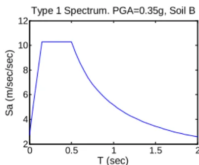
For the following case studies the seismic action will be represented by the Type 1 elastic response spectrum defined by EC8-1. The parameters describing the spectrum correspond to a ground type B (S = 1.2, TB = 0.15
sec, TC = 0.5 sec, TD = 2.00 sec), 5% viscous damping (η = 1) and ground acceleration equal to 0.35g. The
response spectrum is presented in Fig. 2.
0 0.5 1 1.5 2 2 4 6 8 10 12
Type 1 Spectrum. PGA=0.35g, Soil B
T (sec) S a ( m /se c/ se c)
Fig. 2 – Elastic response spectrum used for the analyses.
4.2 Considered structures
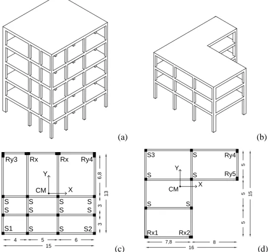
The following two case studies are analysed to illustrate the proposed methodology: a 5-storey building and a 3-storey building that are represented in Fig. 3(a) and 3(b), respectively. The 5-storey structure has the typical plan view of Fig. 3(c). All five storeys have a height of 3 m and the columns’ cross sections are square S 40×40 cm2 and rectangular Rx 80×40 cm2, Ry 40×80 cm2 with constant dimensions throughout the height. All beams have a cross section of 25×60 cm2. The 3-storey structure has the typical corner-shaped plan view shown in Fig. 3(d) and has a 4 m height first storey and two upper storeys with 3 m height each. The columns’ cross sections of the 3-storey building are square S 40×40 cm2 and rectangular Rx 60×40 cm2, Ry 40×60 cm2, constant throughout the height. The beam cross sections are all 25×55 cm2. The modulus of elasticity in both buildings is considered equal to 25 GPa. A 50% reduction of the stiffness is assumed according to the EC8-1 provisions. Both structures are subjected to the analytical procedure presented in section 3.2 and the ASIcrit for selected
vary from 0º to 360º in steps of 1º. The comparison of these results to validate the proposed methodology is then performed.
(a)
(b)
4 5 6 15 3 3 6, 8 13 X Y S1 S S S S S S S2 S S S S Ry3 Rx Rx Ry4 CM(c)
7,8 8 5 5 5 15 16 X Y CM S S Rx1 S3 S S Rx2 S Ry5 Ry4(d)
Fig. 3 – 3D representation of the 5-storey structure (a) and the 3-storey structure (b) and their typical plan views (c), (d), respectively (dimensions in m).
4.3 Results of the analyses
4.3.1 5-storey building
The 5-storey building has fundamental periods along the X and Y axes of 0.93 sec and 0.98 sec, respectively. By assuming a 1st mode distribution of the lateral forces and by applying the procedure described in [17], the location of the fictitious torsional axis is determined with respect to the CM(X,Y), (xfict,yfict) = (-0.47,0.88) m.
Subsequently, the angle α01 = 90.0 o
is determined, which defines the orientation of the optimum principal axis I with respect to X. The uncoupled fundamental periods along the optimum principal axes are TI = 0.97 sec and
TII = 0.92 sec. It is observed that both TI and TII fall on the third branch of the spectrum (Fig. 2), thus the base
shear will vary for different ASIs.
For the determination of the ASIcrit of the horizontal displacement of the vertical structural elements of
each storey, five static condensations are performed, each one considering the dofs of the respective storey as masters. For the sake of the present study, the ASIscrit results for the centre of mass CM and for the four corner
columns, shown in Fig. 3(c), are presented. The ASIscrit that lead to the maximum resultant displacement for
angles calculated analytically using the methodology presented in section 3.2 (ASIcr Anal
) while the second column presents the critical angles determined by the parametric analysis (ASIcr
Param
).
Table 1 – The ASIs that lead to the maximum resultant displacement of the columns of the 5-storey building, determined from the proposed analytical procedure (Anal) and from the parametric analysis (Param).
Elem Stor.
CM S1 S2 Ry3 Ry4
Anal. Param. Anal. Param. Anal. Param. Anal. Param. Anal. Param.
1st 220.0 219 168.9 169 210.5 210 306.0 306 246.9 246 2nd 253.6 253 168.9 169 218.4 218 123.6 123 252.8 253 3rd 258.6 258 169.7 170 222.2 222 123.2 123 255.4 255 4th 261.1 261 169.7 170 224.8 224 122.3 122 256.8 257 5th 263.2 263 168.7 169 227.7 227 120.8 121 258.0 258
4.3.2 3-storey building
The 3-storey structure has fundamental periods along the X and Y axis of 0.69 sec and 0.59 sec, respectively. Similarly to the procedure followed for the 5-storey building, but assuming a uniform distribution of the base shear along the height of the building, the fictitious torsional axis is determined with respect to the CM(X,Y), (xfict,yfict) = (1.38,-1.00) m. Subsequently, the angle α01 = 0.0
o
is determined. The uncoupled fundamental periods along the optimum principal axes, which are parallel to X and Y, respectively, are TI = 0.68 sec and
TII = 0.57sec. It is observed that both TI and TII fall on the third branch of the spectrum. For the determination of
the ASIcrit of the horizontal displacement of the different columns of each storey, three static condensations are
performed and the methodology presented in section 3 is applied. The results corresponding to the centre of mass CM and all five corner columns Rx1, Rx2, S3, Ry4 and Ry5, shown in Fig. 3(d), are presented in Table 2. Similarly to Table 1, the first column of each element shows the results of the analytical procedure (ASIcr
Anal
), while the second column presents the results obtained from the parametric analysis (ASIcr
Param
).
Table 2 – The ASIs that lead to the maximum resultant displacement of the columns of the 3-storey building, determined from the proposed analytical procedure (Anal) and from the parametric analysis (Param).
Elem
Stor.
CM Rx1 Rx2 S3 Ry4 Ry5
Anal. Param. Anal. Param. Anal. Param. Anal. Param. Anal. Param. Anal. Param.
1st 42.2 42 88.3 89 300.9 302 50.4 50 16.5 18 178.5 177
2nd 22.6 25 282.3 284 317.9 318 41.8 42 11.7 13 177.4 177
3rd 13.7 17 308.6 310 326.7 326 36.1 37 10.0 12 177.9 178
4.3 Discussion
Tables 1 and 2 summarize the results obtained from the application of the proposed methodology for selected elements of the 5-storey and 3-storey buildings, respectively, as well as the real ASIcr
Param
obtained from the parametric analyses. It is observed, as previously stated also by other researchers, that each column reaches its maximum displacement for a different ASIcrit and that the ASIcrit of one column also varies for different storeys.
Although the ASIscrit do not seem to follow any constant trends, their straightforward determination is possible
by the proposed methodology. It is observed that for all the analysed elements, the ASIcrit was determined with a
sufficient accuracy. The difference between the ASIcr Param
and ASIcr Anal
is negligible and does not exceed two degrees except in one case, represented by the bold font in Table 2, where the difference is three degrees. The errors of up to one degree may be explained by the resolution of the angle step used for the parametric analysis, while the errors larger than that are due to the assumption of a perfect elliptical shape to represent the relation between the uncoupled fundamental periods.
In order to quantify and assess the induced error, the difference between the displacement that corresponds to the ASIcrit obtained from the analytical procedure and the maximum displacement obtained from the
parametric analysis for all ASIs, normalized by the latter, is determined. Regarding the 5-storey structure, the error for all parameters was found to be lower than 0.01%. For the case of the 3-storey structure, Table 3 presents the results of the error. It is observed that for this case, the induced error is practically negligible also, since it does not exceed 0.03%. Based on these results, it can be considered that the proposed analytical methodology is able to determine adequately the ASIcrit for general multi-storey buildings.
Table 3 – The % error between the displacement that corresponds to the ASIcrit determined from the analytical
methodology and the maximum displacement obtained from parametric analysis for the 3-storey building.
Elem Stor. CM Rx1 Rx2 S3 Ry4 Ry5 1st 0 % 0.008 % 0.007 % 0 % 0.017 % 0.002 % 2nd 0.015 % 0.011 % 0 % 0 % 0.008 % 0 % 3rd 0.025 % 0.001 % 0.005 % 0.002 % 0.011 % 0 %
6. Conclusions
The current paper presented an analytical methodology for the determination of the ASIcrit in the context of the
seismic safety assessment of existing RC buildings with lateral force analysis procedures. The methodology comprises an extension of an existing study for the case of general multi-storey buildings in which the analysis with lateral forces is allowed by the standard earthquake analysis provisions. In the context of seismic safety assessment procedures, storey displacements were selected as demand parameters.
The methodology has been proven to lead straightforwardly to the exact value of the ASIcrit in buildings
with a real elastic axis, while its application for general multi-storey buildings remained a challenge. The use of structural condensation techniques led to the procedure proposed in the current paper which allowed the application of the methodology in those cases as well. The presented case study applications have shown that the ASIcrit calculated by the proposed methodology provides very good estimates of the real ASIcrit. The angles
determined by the proposed analytical procedure were verified by the parametric analysis results and the differences did not exceed two degrees except in one case. In the cases where there was a mismatch between the angles determined by the analytical procedure and the parametric analysis, errors in the maximum displacements were practically negligible. The observed errors in the angle determination are attributed to the resolution of the angle step during the verification by the parametric analysis and to the assumption of the relation between the uncoupled periods in the analytical procedure.
The competitive advantage of the presented methodology is the low demand in computational power and time, as opposed to the parametric analysis for different ASIs that would be required in order to reach the same results. It should be noted herein that the purpose of the paper is not to discuss the selection of the critical demand parameter that should be used for the seismic assessment procedure, but to provide an analytical solution for the case of storey displacements. According to this solution the ASIcrit that leads to the maximum
displacement of a specific column of a storey can be obtained straightforwardly, without the need for multiple analyses and without the use of the conventional combination rules provided by standards which are of questionable validity. Since the requirements of the methodology are the mechanical and geometrical characteristics of the structure, as well as the elastic response spectrum, the presented methodology may be easily implemented in a finite element software. Lastly, more buildings with different configurations in plan and in elevation need to be analysed for the validation of the methodology for a wider variety of buildings.
7. Acknowledgements
The first author would like to acknowledge the financial support from the Foundation of Science and Technology (FCT) of Portugal through the grant PD/BD/113681/2015.
8. References
[1] Newmark N (1975): Seismic Design Criteria for Structures and Facilities: Trans-Alaska Pipeline System. U.S. National
Conference in Earthquake Engineering, Ann Arbor, Michigan.
[2] Rosenblueth E, Contreras H (1977): Approximate Design for Multi-component Earthquakes. Journal of the
Engineering Mechanics Division, 103 (5), 881–893.
[3] CEN (2004): EN 1998-1 Eurocode 8: design of structures for earthquake resistance, part 1: general rules, seismic actions and rules for buildings. European Committee for Standardization.
[4] Lopez OA, Chopra AK, Hernandez JJ (2001): Evaluation of combination rules for maximum response calculation in multicomponent seismic analysis. Earthquake Engineering & Structural Dynamics, 30 (9), 1379–1398.
[5] Rigato AB, Medina RA (2007): Influence of angle of incidence on seismic demands for inelastic single-storey structures subjected to bi-directional ground motions. Engineering Structures, 29 (10), 2593–2601.
[6] Hosseini M, Salemi A (2008): Studying the effect of earthquake excitation angle on the internal forces of steel building´s elements by using nonlinear time history analyses. 14th World Conference on Earthquake Engineering, Beijing, China.
[7] Menun C, Der Kiureghian A (1998): A replacement for the 30%, 40%, and SRSS rules for multicomponent seismic analysis. Earthquake Spectra, 14 (1), 153–163.
[8] Lopez OA, Chopra AK, Hernandez JJ (2000): Critical response of structures to multicomponent earthquake excitation. .
Earthquake Engineering & Structural Dynamics, 29 (12), 1759–1778.
[9] Athanatopoulou AM (2005): Critical orientation of three correlated seismic components. Engineering Structures, 27 (2), 301–312.
[10] Cantagallo C, Camata G, Spacone E (2015): Influence of ground motion selection methods on seismic directionality effects. Earthquakes and Structures. 8 (1), 185–204.
[11] Sebastiani PE, Liberatore L, Lucchini A, Mollaioli F (2014): Simple models to predict the most critical incidence angle for buildings under bi-directional near-fault excitations. 2nd European Conference on Earthquake Engineering and
Seismology, Istanbul, Turkey.
[12] Morfidis KE, Athanatopoulou AM, Avramidis IE (2008): Effects of seismic directivity within the framework of the lateral force procedure. 14th World Conference on Earthquake Engineering, Beijing, China.
[13] Quadri SA, Madhurin M (2014): Investigation of critical angle of seismic incidence for the analysis of RCC frames.
12th IRF International Conference, Pune, India.
[14] Skoulidou D, Romão X (2016): Determination of the critical angle of seismic incidence in stardandised procedures for the seismic safety assessment of 3D RC buildings. 10o Congresso National de Sismologia e Engenharia Sísmica, Açores, Portugal.
[15] Roussopoulos A (1932): Distribution of horizontal forces by a rigid plate in spatial structures: case of seismic forces, their distribution and regime. Technika Chronika, Techical Chamber of Greece, 17, 871-884 (In Greek).
[16] Makarios TK, Anastassiadis K (1998): Real and fictitious elastic axes of multi-storey buildings: Theory. Structural
Design of Tall and Special Buildings. 7 (1), 33-55.
[17] Athanatopoulou AM, Doudoumis IN (2008): Principal directions under lateral loading in multistorey asymmetric buildings. Structural Design of Tall and Special Building. 17 (4), 773–794.
[18] Anastassiadis K (1989): Antiseismic structures. Volume I. ZITI, 1st vol. (In Greek).
[19] CEN (2005): EN 1998-3 Eurocode 8: design of structures for earthquake resistance, part 3: assessment and retrofitting of buildings. European Committee for Standardization.
[20] Riddel R, Vasquez J (1984): Existence of centers of resistance and torsional uncoupling of earthquake response of buildings. 8th World Conference on Earthquake Engineering. San Francisco, USA.
[21] Marino EM, Rossi PP (2004): Exact evaluation of the location of the optimum torsion axis. Structural Design of Tall
and Special Building, 13 (4), 277–290.