Diana Guerra de Paiva
Licenciatura em Engenharia Biomédica
Liquid Crystalline Microenvironments
For Tissue Engineering
Dissertação para obtenção do Grau de Mestre em Engenharia Biomédica
Orientador: Professor Doutor Pedro Granja, Investigador Principal,
INEB - Instituto de Engenharia Biomédica, Universidade do Porto
Co-Orientador: Doutora Susete Fernandes, Investigadora em
Pós-Doutoramento, CENIMAT/I3N
–
Departamento de Ciências dos
Materiais, Faculdade de Ciências e Tecnologia da Universidade
Nova de Lisboa
Júri:
Presidente: Prof. Doutora Célia Maria Reis Henriques Arguente: Prof. Doutora Maria Teresa Varanda Cidade Vogal: Prof. Doutor Pedro Lopes Granja
i Diana Paiva Dissertação de Mestrado em Engenharia Biomédica
Acnowledgements
I want to express my gratitude to Dr. João Paulo Borges, which not being an official supervisor, always helped and guided me; to Dr. Pedro Granja and Dr. Susete Fernandes for the guidance and support they gave to me. Thank you for the knowledge and work skills gave to me and the opportunity to work with different methodologies. I am grateful for the opportunity to perform my thesis in two excellent laboratories: CENIMAT|I3N and INEB – Instituto de Engenharia Biomédica and being kindly received in both. Thank you for the enthusiasm with my work and for your great ideas and support!
At CENIMAT|I3N, besides my co-supervisor, Dr. Susete Fernandes which had the patience to transmit her knowledge and enthusiasm for science, to Dr. Coro Echeverria for her support and help and to Dr. Daniela Gomes for the patient on our Scanning Electron Microscopy session at CENIMAT|I3N.
At INEB I would like to thank to MSc Sara Neves who helped me with her expertise and knowledge in rheology and Dra. Filipa Sousa, who introduced me to cell culture. Thank you both for the sincerity, orientation and suggestions. Thank you Ricardo Vidal, for the advice and collaboration in numerous situations and to all members of the Biocarrier group, which always kindly helped me through the thesis. Thank you to Dra. Paula Sampaio from IBMC (Instituto de Biologia Molecular e Celular) for the help with the Polarized Optical Microscope. To the IBMC Transmission Electron Microscopy technicians, thank you for their help and expertise. At CEMUP (Centro de Materiais da Universidade do Porto), to the Scanning Electron Microscopy technicians thank you for the aid.
I cannot forget of my fellow colleagues and friends both in CENIMAT and INEB who were always there for a conversation and a brief moment of relaxation.
To my friends that accompanied me through this 5 years adventure. To my boyfriend Miguel, who always had the patience to listen in difficult hours and always motivated and supported me. A big thank you.
iii Diana Paiva Dissertação de Mestrado em Engenharia Biomédica
Abstract
In this present work, gels with liquid crystalline (LC) phases were studied based on cellulose and collagen. The cellulose was further incorporated in a polymer matrix (polyvinyl alcohol) and in a biocompatible material (glycerol), in order to produce gels with LC phases. The LC phases and other properties of the gels were further investigated in order to determine relationships between structure/properties. Preliminary cellular studies were done to unravel the influence of the LC phase in cell proliferation and the changes in the LC phase due to the presence of the cells.
Nanocrystalline cellulose (NCC) with different aspect ratio, were obtained by acid hydrolysis with sulfuric acid at different reaction times. Gelation of collagen type I was not achieved. The NCC/PVA gels did not presented LC patterns.
NCC/glycerol gels with NCC concentration higher than 7% (w/w) showed, through polarized optical microscopy, a fingerprint texture characteristic of the chiral nematic ordering of the NCC. The pitch of LC phase, increase with the NCC length and no significant variations were observed in gels with higher NCC content. For cell culture studies the 7% (w/w) NCC concentration was selected and the pH of the gels was increased by incubation with culture medium and an increase in the pitch size was noticed. A negative zeta potential of the gels was observed even after pH increase. No chemically modifications were observed by ATR-FTIR after increasing the gels’ pH. Preliminary rheological studies gave a good indication of the materials’ viscoelastic properties and its thixotropic behaviour. Exploratory cellular tests showed low cell adhesion and cytotoxic tests led to conclude that 48 hours of incubation with culture medium is needed before any cellular studies.
This study shown that the NCC/glycerol gel is a promising material to use in tissue engineering applications.
v Diana Paiva Dissertação de Mestrado em Engenharia Biomédica
Resumo
Neste trabalho, géis com fases liquido-cristalinas (LC) de celulose e colagénio foram estudados. A celulose foi incorporada posteriormente numa matriz polimérica (álcool polivinílico) e num material biocompatível (glicerol). As fases LC, bem como outras propriedades dos géis foram posteriormente estudadas para relacionar as estruturas LC com as propriedades dos géis. Estudos celulares preliminares foram efetuados para determinar a influência da fase LC na proliferação celular e as alterações dessa mesma fase com a presença de células.
Diferentes tempos de hidrólise da celulose com ácido sulfúrico foram efetuados e celulose nanocristalina (NCC) com diferentes comprimentos obtida. A gelificação do colagénio não foi conseguida e os géis de NCC/PVA não apresentaram uma organização liquido-cristalina.
Géis de NCC/glicerol observados por microscopia ótica polarizada (POM), apresentam birrefringência e a partir da concentração de 7%NCC no gel, têm uma textura denominada “impressão
digital”, característica da fase LC nemática quiral. O passo dos géis aumenta com o comprimento das
NCC. Não se verificou uma variação significativa do passo para concentrações de NCC nos géis mais elevadas. A concentração de 7%NCC foi selecionada para os estudos celulares, tendo o pH dos géis aumentado para incubação com meio de cultura, observando-se o aumento do passo dos géis. Verificou-se um potencial zeta negativo tanto nos géis com e sem incubação em meio de cultura. Por ATR-FTIR não se observaram alterações significativas dos géis após aumento de pH. Com estudos reológicos preliminares, foi possível caracterizar as propriedades viscoelásticas e a tixotropia do material. Testes celulares preliminares demonstraram fraca adesão celular aos géis, contudo testes de citotoxicidade revelaram a necessidade de 48 horas de incubação dos géis antes de qualquer estudo celular.
Este trabalho demonstrou que géis de NCC/glicerol são promissores para serem utilizados em engenharia de tecidos.
vi Diana Paiva Dissertação de Mestrado em Engenharia Biomédica
Considerations
In nature, cellulose and collagen are one of the most common macromolecules that form liquid crystalline phases. It is believed that liquid crystal phases have a key role in tissue differentiation and is an aim of this thesis to prove this theory. [1] Previous works had shown the importance and the applicability of liquid crystals such as a thermotropic liquid crystals suitable for growth of mammalian cells [2][3] and the alteration of the liquid crystal conformation in the presence of certain chemical substances or physical changes. [4] The main goal of this thesis was to prepare liquid crystalline gels based on nanocrystalline cellulose and collagen. Physical and chemical characterizations of the gels were done and preliminary rheological and cellular studies were performed.
The research performed during this thesis was conducted in two different institutions: DCM –
Departamento de Ciências dos Materiais at Faculdade de Ciências e Tecnologia, Universidade Nova
de Lisboa (FCT/UNL) in the group SBM – CENIMAT|I3N and INEB – Instituto de Engenharia Biomédica at Universidade do Porto (UP) in the group BIOCARRIER.
Chapter I brings an overview of the state of the art of the use of liquid crystals in tissue engineering as well as their theoretical principles. It also introduces the main materials used during the experimental part of the thesis and its current usages in the tissue engineering field.
Chapter II describes the preparation of the studied biomaterials as well as, the characterization techniques and studies performed on the samples (physical, chemical and biological characterization, as well as, rheological experiments).
In the Chapter III the results obtained were presented and discussed.
vii
Diana Paiva Dissertação de Mestrado em Engenharia Biomédica
Contents
Acnowledgements ... iAbstract ... iii
Resumo ... v
Considerations ... vi
Abbreviations ... xvii
Chapter I – Introduction ...1
1. Liquid Crystals:...1
1.1. Liquid Crystals: Definition and Characterization...1
1.2. Liquid Crystals in biology: ...3
1.3. Liquid crystals in biomedical applications: ...4
2. Cellulose and collagen: two liquid crystalline biomaterials: ...6
3. Physical and chemical gels: ...8
3.1. Hydrogels: ...9
4. Polyvynil Alcohol (PVA): ... 10
5. Cell adhesion mechanisms: ... 11
5.1. Protein adsorption:... 11
5.2. Non-fouling biomaterials: ... 11
5.3. Improvement of cell adhesion in non-fouling materials:... 12
6. Fibroblasts: a cell culture perspective. ... 12
6.1. Fibroblasts: ... 12
6.2. Fibroblasts in tissue engineering: ... 13
6.3. Fibroblasts and liquid crystalline structures: ... 14
Chapter II - Materials and Methods... 15
1. Nanocrystalline Cellulose gels: ... 15
1.1. Materials: ... 15
1.2. Acid hydrolysis of cellulose: ... 15
1.3. NCC/glycerol gel formation: ... 16
viii
Diana Paiva Dissertação de Mestrado em Engenharia Biomédica 2. Collagen gels formation: ... 17
2.1. Gel formation: ... 17
3. Characterization of the Nanocrystalline cellulose and its gels: ... 18
3.1. Fourier Transform infra-red spectroscopy (FTIR): ... 18
3.2. X-Ray Diffraction:... 18
3.3. Scanning Electron Microscopy (SEM): ... 18
3.4. Polarized Optical Microscopy (POM): ... 19
3.5. Transmission electron microscopy (TEM): ... 20
4. Integrity tests: ... 22
4.1. Non-mobility test: ... 22
4.2. PBS stability test: ... 22
4.3. pH and culture medium stability test: ... 22
4.4. Swelling behaviour evaluation: ... 23
5. Chemical analysis of the NCC/glycerol gels: ... 23
5.1. Electro kinetic Analysis (EKA): ... 23
6. Rheology ... 24
6.1. Viscometry measurements: ... 24
6.2. Oscillatory measurements: ... 24
7. Cell culture ... 26
7.1. Specific cell-culture gel preparation methods: ... 26
7.2. Cell culture: ... 26
7.3. Cell Adhesion: ... 26
7.4. Citotoxicity assays: ... 27
7.5. Resazurin metabolic test: ... 27
Chapter III - Results and Discussion... 29
1. NCC synthesis and characterization ... 29
1.1. Synthesis: ... 29
1.2. Characterization: ... 30
2. Structural characterization of NCC gels ... 33
ix
Diana Paiva Dissertação de Mestrado em Engenharia Biomédica 2.2. Polarized Optical Microscopy (POM): ... 34
2.3. Transmission electron microscopy: ... 36
3. Integrity tests: ... 37
3.1. PBS stability test: ... 37
3.2. Non- mobility test: ... 37
3.3. pH stability test: ... 38
3.4. Swelling behaviour: ... 40
3.5. Electro kinetic analysis (EKA): ... 41
3.6. ATR-FTIR: ... 41
4. Rheology: ... 42
4.1. Frequency sweeps: ... 43
4.2. Viscometry assays ... 45
4.3. Stress sweeps ... 47
4.4. Additional rheological tests: ... 49
5. Cell culture ... 51
5.1. Cell Adhesion: ... 51
5.2. Cytotoxicity assays: ... 52
5.3. Final remarks: ... 53
6. Collagen gels ... 54
Chapter IV - Conclusion ... 55
Chapter V - Future directions ... 57
References: ... 58
xi Diana Paiva Dissertação de Mestrado em Engenharia Biomédica
List of figures
Figure 1.1 – Schematic of the thermal transitions regarding the liquid crystalline state. ...1 Figure 1.2 – Three dimensional representation of the cholesteric liquid crystalline phase (plywood
model). On each level the molecular arrangement is represented by parallel lines and they rotate continuously in a small and constant angle. P0 – pitch. [13] ...2
Figure 1.3 – Schematic of three phases of the thermotropic liquid crystals: Nematic, Smectic and
Cholesteric. Adapted from [9]. ...3
Figure 1.4 – Molecular structure of cellulose representing the cellobiose unit as a repeating unit showing
the non-reducing (left) and reducing (right) end-groups. This structure also shows that the repeated anydroglucopyranose units (AUG) are rotated of 180º with respect to each other, due to β -linkage constrains (n=DP, degree of polymerization). ...6 Figure 1.5– Illustration of: a) chemical gels; b) physical gels; c) crystalline chemical gel; d)
Liquid-crystalline physical gel. Adapted from [45]. ...9
Figure 1.6 – Illustration of the connective tissue cell family. The fibroblasts can in certain conditions of
extracellular matrix, growth factors, cell shape and hormones differentiate in other cells of the connective tissue family. Adapted from [67]. ... 13
Figure 2.1 – Schematic diagram of a Scanning electron microscopy (SEM) device. Adapted from [88].
... 19
Figure 2.2 – Schematic of a polarized optical microscope. Adapted from [90]. ... 20 Figure 2.3 –Schematic diagram of a Transmission electron microscopy (TEM) device. Adapted from
[88]. ... 21
Figure 2.4 – pH probe used to measure the pH of the gels during the pH integrity test. ... 23 Figure 2.5 – Shear rate ramps applied to the sample for the hysteresis loop tests. ... 24 Figure 2.6 – Oscillatory assays performed to the gels. A - Oscillatory stress sweep, followed by an application of the LVR conditions. B - Oscillatory test in which a shear stress out of the LVR is applied for 1 minute followed by the application of a shear stress within the LVR for 4 minutes; this was repeated 15 times for each gel. ... 25
Figure 3.1 – Schematic representation of the acid hydrolysis reaction of micro-cellulose to afford
nanocrystalline cellulose with sulfate half-ester groups in an acid form. ... 29
Figure 3.2 – FTIR spectrum of a thin film of nanocrystalline cellulose obtained by the reaction of acid
hydrolysis of microcrystalline cellulose during 130 min. ... 30
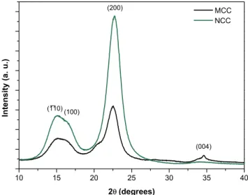
Figure 3.3 – XRD diffractograms of unmodified microcrystalline cellulose (MCC) and NCC obtained at
130 min of acid hydrolysis reaction time. The characteristic peaks of cellulose type I are highlighted in the diffractogram. ... 31
Figure 3.4 – SEM images of nanocrystalline cellulose obtained from reactions with different acid
xii Diana Paiva Dissertação de Mestrado em Engenharia Biomédica
Figure 3.5 – Photograph of a 2.12% (w/w) NCC aqueous suspension showing birefringence,
characteristic of the presence of a LC phase, resultant of the reflection of light of the suspension observed between cross polarizers. ... 33
Figure 3.6 – NCC/glycerol gel with 7%NCC content (w/w) in the gel. . ... 33 Figure 3.7 – Photographs of the NCC/PVA gels with different NCC/PVA ratio. NCC content % (w/w):
A –0.65%, B – 4.85% and C – 10%. All percentages of NCC presented are with regarding to the dry weight of PVA. ... 34
Figure 3.8 – Photographs obtained with POM taken between cross polarizers and a 20x magnification.
A – NCC/glycerol gel with 5% (w/w) NCC; B – NCC/PVA gel with 4.85% NCC dry weight of PVA. ... 34
Figure 3.9 – Pictures of NCC/glycerol gels (130 minutes acid hydrolysis time), observed through POM
with cross polarizers with a 20x magnification. A – NCC/glycerol gel with 7% (w/w) NCC; B – NCC/glycerol gel with 10% (w/w) NCC; C – NCC/glycerol gel with 18% (w/w) NCC. ... 35
Figure 3.10 – Pictures of NCC/glycerol gels with 7% (w/w) NCC content, observed through POM with
cross polarizers and a 20x magnification. A –NCCs40’ gel; B –NCCs70’ gel ... 36
Figure 3.11– Pictures of NCC/PVA gels with 4.85% (w/w) NCC of the dry weight of the polymer... 36 Figure 3.12 – Photographs of the NCC gels after the PBS stability test. The NCC/glycerol gel did not
suffer any structural deformation. A – NCC/glycerol gel with 5% NCCs concentration; B and C are NCC/PVA gels with 0.65% and C with 10% of NCCs concentration regarding the PVA dry weight. .... 37
Figure 3.13 – Photographs of the NCC/glycerol gels after two weeks of inversion. The gels did not alter
their position during the experience. In some photographs it is possible to observe a black mark of the initial position of the gel and confirm the absence of movement of the gel. A – NCC/glycerol gel with 5% NCCs concentration; B - NCC/glycerol gel with 10% NCCs concentration. ... 38
Figure 3.14 – Photograph of the NCC/glycerol gel after the pH stability test with cell culture medium.
The gel changes the color of the medium due to its acidity. ... 39
Figure 3.15 – Photographs taken through polarized optical microscopy with cross polarizers and 20X
magnification of the NCC/glycerol gels after the pH stability test. A – “Fingerprint” textures of the NCCs130’ gel after the pH equilibrium with PBS. B, C and D shows fingerprint textures from: A – NCCs130’; B-NCCs70’; C –NCCs40’ with pH equilibrium with culture medium. ... 40
Figure 3.16 – ATR-FTIR spectra of NCC/glycerol gels. Red –NCCs40’; Black –NCCs40’ with culture
medium incubation; Purple - NCCs70’; Light blue –NCCs70’ with culture medium incubation; Dark blue –NCCs130’ and Green –NCCs130’ with culture medium incubation... 42
Figure 3.17 – Frequency sweeps of the NCC/glycerol gels with 7% NCC (w/w) (A - NCCs40’, B - NCCs70’ and C - NCCs130’) with a fixed shear stress of 10 Pa. ... 44
Figure 3.18 – Thixotropic behaviour of the NCC/glycerol gels with 7% NCC (w/w) (A - NCCs40’, B - NCCs70’ and C - NCCs130’) assessed by the hysteresis loop experiment... 45
Figure 3.19 – Shear viscosity of the NCC/glycerol gels with 7% NCC (w/w) (A - NCCs40’, B - NCCs70’
and C - NCCs130’) obtained from the shear rate ramps performed for the hysteresis loop tests. ... 46
Figure 3.20 – A - Oscillatory stress sweep from 1 Pa to 4000 Pa followed by an application of the LVR
xiii Diana Paiva Dissertação de Mestrado em Engenharia Biomédica
NCCs70’ and 3 - NCCs130’) at 2Hz, immediately followed by the application of a frequency and shear
stress values within the LVR. ... 48
Figure 3.21 – Oscillating fixed stress of 4000 Pa at a 2Hz frequency applied for 1 minute followed by
the application of the LVR conditions for 4 minutes The samples used are NCC/glycerol gels with 7% NCC (w/w) (A - NCCs40’, B - NCCs70’ and C - NCCs130’). ... 49
Figure 3.22 – Gels incubated in cell culture medium after the rheological measurements: A – Gel
incubated and transferred from the well plate with a spatula; B – Gel prepared with the gel casters. .. 50
Figure 3.23 –Oscillation test of the NCCs40’ gel after incubation with culture medium, with fixed shear stress and frequency values, both within the LVR of the NCCs40’ gel (2 Hz, 10 Pa). ... 50
Figure 3.24 – Results from the 1st day of in vitro cell adhesion test for the NCCs130’, NCCs70’ and
NCCs40’. A –Results from Resazurin fluorescence test. B – Relative cell viability graphic. Significance
values were calculated by Mann-Whitney U test (p≤0.0001). ... 51
Figure 3.25 –Results from in vitro direct and indirect contact cytotoxicity assays for the NCCs130’ gel.
A –Results from Resazurin fluorescence test. B - Relative cell viability graphic. Significance values were calculated by Mann-Whitney U test (p≤0.0001). ... 52
Figure A1– Schematic of the sample response to an applied shear stress. Adapted from [112]. ... 65 Figure A2– Graphic of NCC’s length versus acid hydrolysis time and comparison with the data from
xv
Diana Paiva Dissertação de Mestrado em Engenharia Biomédica
List of tables
Table 1.1– Biological liquid crystals and type of LC phase: ...4Table 2.1 – Amount of NCC and glycerol used in the NCC/glycerol gels preparation. Final NCC content in the gels. ... 16
Table 2.2 – Amount of NCC and PVA used in the NCC/PVA gels preparation. Final NCC content in the gels. ... 17
Table 3.1 – Crystallinity index and crystallite size calculated from the x-ray diffractograms for MCC and NCC obtained with 130 minutes of acid hydrolysis... 31
Table 3.2– Measurements of width and length of NCC obtained with different hydrolysis time. ... 32
Table 3.3 – Pitch measurements on NCCs/glycerol gels. ... 35
Table 3.4 – pH measurements of the NCCS/glycerol gels ... 38
Table 3.5 – Pitch measurements of the NCC/glycerol gels after pH equilibrium with cell culture medium. ... 40
Table 3.6– Electro kinetic analysis results ... 41
Table 3.7– Storage and Loss modulus and phase angle values of the of the NCC/glycerol gels with 7% NCC (w/w) (NCCs40’, NCCs70’ and NCCs130’) from the frequency sweep measurements, at 2 Hz and using a 10Pa shear stress. ... 45
Table 3.8– Summary of the properties of the NCC/glycerol gels with 7% NCC (w/w) (NCCs40’, NCCs70’ and NCCs130’) retrieved from oscillatory stress sweep test followed by application of LVR conditions for 5 minutes. ... 47
xvii Diana Paiva Dissertação de Mestrado em Engenharia Biomédica
Abbreviations
LCs– Liquid Crystals
NCC– Nanocrystalline Cellulose
LCTFs – Liquid Crystal Tunable Filters SLMs– Spatial Light Modulation n– Director (unitary vector) P –Cholesteric pitch
AGU–Anydroglucopyranose DP – Degree of Polymerization PEG– Polyethyleneglycol PVA – Polyvynil alcohol Gly– Glycine
Pro– Proline
Hyp– Hydroxyproline PCL– Polycaprolactone PC– Phosphorylcholine
SBMA– Sulfobetaine Methacrylate CBMA– Carboxybetaine Methacrylate HDNF –Human Dermal Neonatal Fibroblasts FBS – Fetal Bovine Serum
DMEM –Dulbecco’s Modified Eagle Medium
EDTA –Ethylenediamine Tetracetic Acid PBS – Phosphate-buffered Saline
DF-1 – Dermal Fibroblast Culture Medium
FTIR– Fourier Transform infra-red spectroscopy ATR – Attenuated Total Reflectance
SEM– Scanning Electron Microscopy CCD– Charged Couple Device
xviii Diana Paiva Dissertação de Mestrado em Engenharia Biomédica
MCC – Microcrystalline Cellulose
1 Diana Paiva Dissertação de Mestrado em Engenharia Biomédica
Chapter I
–
Introduction
1. Liquid Crystals:
1.1. Liquid Crystals: Definition and Characterization
Liquid crystals (LCs) are widely used in different fields such as tissue engineering [2], drug delivery [6] and electronics, for example as a component in a TV screen. [7] LCs are well known for their intermediate state between isotropic liquids and crystalline solids with a three dimensional structure (figure 1.1). Thus, their chemistry and physics has been profoundly studied throughout the years, having a rapid advance after 1960. The discovery of the liquid crystalline state was made by the botanist Freiderich Reinitzer in 1888. Reinitzer described a colour arise when melting cholesteric acetate and cholesteric benzoate. In addition, two melting points of the cholesteric benzoate were registered and for the first time the term liquid crystal was applied. [8] In 1904, Otto Lehmann, a German physicist, with whom Reinitzer corresponded, proceeded with the study of this state of matter and later associated these properties with some biological samples. From 1960 with the application of liquid crystals in televisions and other electronic devices, numerous progresses were made in this field. [9]
Figure 1.1 – Schematic of the thermal transitions regarding the liquid crystalline state.
2 Diana Paiva Dissertação de Mestrado em Engenharia Biomédica
temperature, pressure or concentration is a precursor of a mesophase or a liquid crystalline phase) and also on the temperature and pressure conditions. [8]
Thermotropic LCs integrate rod-like, disk-like or banana-shaped molecules that arrange in three different phases: nematic, cholesteric and smectic. [11] The most common liquid- crystal phase is the nematic, identified by a long range orientational order with the direction of a dimensionless vector n, called director. In the nematic phase molecules tend to align in the same
direction as the long axis, that is, in the same direction as the director with no specific positional order. A cholesteric phase or chiral nematic phase is formed by optically active organic compounds (chiral molecules), a mixture of different types of these compounds or a mixture of optically active compounds with nematic liquid crystals. A chiral molecule is one that cannot be superposed to its mirror image. [9] Cholesteric liquid crystals have a helical twist: the director vector, n, pursues a helical form. The distance for a 360ᵒ turn is denominated pitch. Nematic LCs
have an infinite pitch and by chemical or mechanical processes they can be converted to the cholesteric liquid crystalline phase. In the figure 1.2 is represented a three dimensional scheme of this phase, where the molecules are represented by parallel lines and rotate in each level by a constant and small angle. When the rotation reaches 180ᵒ, half pitch is defined. This model is called plywood model. [12]
Figure 1.2 – Three dimensional representation of the cholesteric liquid crystalline phase (plywood model). On each level the molecular arrangement is represented by parallel lines and they rotate continuously in a
small and constant angle. P0 – pitch. [13]
Chiral nematic LCs have unique optical properties. When a perpendicular beam of light with a wavelength much smaller than the pitch reaches the LC, it is broken in two: one perpendicular and other parallel to the alignment axis – this phenomenon is called birefringence. When the pitch is reduced, the beam is converted into a circular polarized wave and the LC shows optical activity. This optical property is dependent on the wavelength of the irradiation beam and on the dielectric constant of the LC material. [9]
3 Diana Paiva Dissertação de Mestrado em Engenharia Biomédica
In figure 1.3 are represented three phases of the thermotropic liquid crystals:
Figure 1.3 – Schematic of three phases of the thermotropic liquid crystals: Nematic, Smectic and Cholesteric. Adapted from [9].
Usually lyotropic liquid crystals are formed by an amphiphilic molecule and a solvent [11] at a given temperature and relative concentrations. These molecules self-aggregate in a minimum energy supramolecular structure and the most prevalent form is the lamellar, where the double layers are parallel to each other and are separated by the solvent. Other lyotropic arrangements consist in cubic, hexagonal, micellar and gel. [9] The most common phase in lyotropic liquid crystals is the chiral nematic but achiral phase like smectic and nematic are also observed. [14]
1.2. Liquid Crystals in biology:
Liquid crystallinity is found in numerous biological molecules such as, proteins, carbohydrates, fats, acid nuclei and virus. Furthermore, the liquid crystalline phase is proved to be involved in the beginning of the formation of biological molecules and it is considered an important step of the differentiation process of cells and tissue [1]; LCs are also responsible for the morphogenesis of tissue, tendons and ligaments. [15] For instance, it was observed that procollagen had pre-cholesteric phases that induced the structure of some animal tissues, which are anisotropic and present a fibrillary structure. [16][17]
4 Diana Paiva Dissertação de Mestrado em Engenharia Biomédica
Cellulose, particularly nanocrystalline cellulose (NCC), in aqueous suspensions, shows liquid crystalline behaviour, being a lyotropic LC, and has a chiral nematic arrangement. [19] On the other hand, collagen molecules are triple helical, thus, also chiral nematic and posteriorly organize into cross-striated fibrils and in a three dimensional network. [20] This type of assembly is present in compact bones, connective tissues and cornea. In human compact bone, collagen type I has arced textures due to the superposition of different molecules orientations at the section plane. [17] In cuticles, the collagen molecules form concentric circles. [12]
In table 1.1 a summary of some biological liquid crystals and its corresponding liquid crystalline phases is presented:
Table 1.1 – Biological liquid crystals and type of LC phase:
Biologic liquid crystal Liquid Crystalline Phase
DNA [9] Chiral Nematic RNA [9] Chiral Nematic Proteins [9] Chiral Nematic Phospholipid bilayer [18] Smectic
Myelin [14] -
Haemoglobin [9] Nematic Chitin [18] [19] Chiral Nematic Cellulose [18] [19] Chiral Nematic Collagen [20] Chiral Nematic
Liquid crystalline behaviour enhances some properties of the biological materials such as elasticity, resistance to load and stress. [21] This characteristic also allows efficient packing and self-assembly of plywood structure and sensor/actuator abilities. [22]
1.3. Liquid crystals in biomedical applications:
5 Diana Paiva Dissertação de Mestrado em Engenharia Biomédica
Chiral nematic printed LC films are being used for temperature and humidity actuators. These LCs are implemented as power generators, smart textiles, artificial muscles, and sensors. The pitch and wettability of these LC superficies change with the radiation beam (temperature). [23]
Another employment of LCs in this field includes: liquid-crystal tunable filters (LCTFs) and spatial light modulators (SLMs). LCTFs are used in spectroscopy, acquiring the spectral signature of a cell, tissue or a biological particle. As an example, the spectral signature of the haemoglobin, present in the blood vessels of human conjunctiva, can be detected by the LCTFs and used to diagnose anaemia by measuring the haemoglobin levels. Allied with optical fibres this technique also allows endoscopic diagnosis. SLMs are used in DNA manipulation and in the investigation of cellular behaviour as well as in in vitro fertilization practices. These devices brought more phase
contrast and led to advances in scanning microscopy. LCs are also used to produce, on a larger scale, lasers with higher optical range and optical power that, with further research, will bring advantages in the biomedical field. LCs nematic droplets can function as lenses with a focal length that can be modulated with an electric field. They can substitute bifocal eyeglasses by switching to near or far vision with the electric stimulus. [11]
A variety of molecules such as antigens, are added to liquid crystals to form chemical and biological sensors. When a surface interaction occurs in the LC, its conformation changes, forming a simple and rapid sensor that doesn´t need biological markers or any kind of energy to function. [11] On the other hand, it was reported that an endotoxin aggregated to LC droplets’ defects, is able to change the droplet´s conformation. [24] Brake et al. observed an alteration of the alignment in LCs, when phospholipids are added to the liquid crystal aqueous interface. [25] In the field of tissue engineering, hydrogels and silicon elastomers with LC properties were applied to the study of cell behaviour. Liquid crystals were added to a cell culture of mammalian cells and it was observed cell proliferation, proving the non-toxicity of certain LCs to this type of cells. [2] Liquid crystalline collagen was reported to align fibroblasts in a parallel direction to the collagen matrix direction, supporting the role of LCs in tissue formation. [26] It was also used to understand the influence of the matrix architecture on cell behaviour. [3] Collagen fibrils, hydrated with a liquid crystalline phase, were shown to successfully grow an amount of fibroblasts, close to the number of fibroblasts presented in the connective tissue, representing an enormous breakthrough in tissue regeneration and in the production of new materials similar to skeletal tissue [27], corneal and in the regrowth of peripheral nerve axons. [28] Genetically engineered liquid crystalline films of virus M13, coated with peptides, are proved to aid in the growth of nerve cells. [29]
6 Diana Paiva Dissertação de Mestrado em Engenharia Biomédica
able to encapsulate, in its lyotropic layer, substances of low and high molecular weight such as, chemical drugs, proteins, peptides and nucleic acids for drug delivery systems. [6]
2. Cellulose and collagen: two liquid crystalline
biomaterials:
Cellulose is the most common and important natural organic polymer and is a long-chain polysaccharide with repeating unites of D-anhydroglucopyranose linked by a β-1,4 glycosidic bond. It´s molecular structure is represented in figure 1.4. The main properties of cellulose are hydrophilicity, chirality, degradability and the formation of supramolecular assemblies by hydrogen bonds, due to the presence of three reactive hydroxyl groups. [31] Cellulose can be found in plants, some bacteria, algae and fungi. [32]
Figure 1.4 – Molecular structure of cellulose representing the cellobiose unit as a repeating unit, showing the non-reducing (left) and reducing (right) end-groups. This structure also shows that the repeated
anydroglucopyranose units (AGU) are rotated of 180º with respect to each other, due to β- linkage constrains (n=DP, degree of polymerization).
Improvement of the knowledge of the reactivity and structural features of cellulose has motivated the search for new types of cellulose-based materials - ethers, esters and nanocellulose.
On the basis of its functions, dimensions and preparation methods three categories of nanocellulose can be considered: microfibrillated cellulose, bacterial nanocellulose and nanocrystalline cellulose. [33]
7 Diana Paiva Dissertação de Mestrado em Engenharia Biomédica
rises above a critical point, observed by the appearance of birefringence and a characteristic fingerprint texture. [34] NCC can also show a parallel alignment when exposed to a magnetic field. [35] Nanocrystalline cellulose has been studied for various tissue engineering applications in the past few years. NCC can be used as scaffolds, films, porous sponges and as hydrogels reinforcement agents, increasing their mechanical properties and biocompatibility. [32] Burt et al. studied the ability of NCC to bind to water soluble antibiotics and cationic NCC to bind to non-ionized hydrophobic anticancer agents, proving that these systems are good drug carriers either in the form of films, hydrogels or microspheres. In blood vessel replacements, NCC also improved the mechanical properties of implant matrices of collagen, gelatin, alginate, chitosan, cotton gauze, polyethylene glycol (PEG) and polyvinyl alcohol (PVA). [36] Yang et al. produced injectable hydrogels of carboxymethyl cellulose and dextran reinforced with cellulose nanocrystals and aldehyde-functionalized NCC, as a chemical cross-linking agent. These hydrogels, with high dimensional stability in swelling experiments and improved mechanical properties, exhibit non-significant cytotoxicity when in contact with 3T3 fibroblast, which opens its use to several biomedical applications such as drug delivery systems or tissue engineering matrices. [37]
Collagen is the most common protein present in the human body and is the main structural element of tissue, skin, bone and cartilage. It is formed by three filaments of polypeptides combined in a left-handed triple helix with 300 nm long and 1.5 nm of diameter. Collagen is characterized by Gly–Pro–Hyp–Gly–X–Y sequences where Gly is glycine; Pro is proline, Hyp is hydroxyproline, X and Y are amino acids, linked by hydrogen bonds between –CO and –NH groups, and by covalent bonds. [26] Its precursor is procollagen, a molecule with N and –C terminals groups that are posteriorly removed to form collagen. [16]
There are 19 types of collagen known. Type I collagen forms most of the extra cellular matrix proteins of dense connective tissue. The hierarchical organisation of these fibrils increases the elasticity of skin, the resistance to stress or shear in tendons, the load in bone and transparency of the cornea. In vitro research proved the existence of liquid crystalline chiral
nematic phase of type I collagen with a long-range helical order. [20] A major interest in collagen in tissue engineering field has grown due to collagen’s biocompatibility, biodegradability, low immunogenicity and toxicity as well as good cell adhesion properties. [27]
8 Diana Paiva Dissertação de Mestrado em Engenharia Biomédica
structures. [41] Kofidis et al., showed, with in vitro studies, that projected collagen devices
colonized with cardyomiocites with continuous and synchronized contractions are close to be suitable to repair cardiac tissue. [42] Collagen type I alone is used as bone substitutes and tissue grafts due to its osteoconductive activity. Furthermore, mixtures of hydroxyapatite with demineralized bone collagen are employed as bone grafts materials. [43]
3. Physical and chemical gels:
Gels are a viscoelastic soft material, which combines a solvent and an elastic cross- linking network. The solvent is captured and adhered in the solid arrangement. If gels are formed by strong chemical bonds they are thermally irreversible and they cannot be disassembled. On the other hand, gels formed by weak and non-covalent interactions can be dismantled. [44] A chemical gel is a polymer 3D network chemically bounded to each other by covalent bonds. Physical gels are 3D assembled structures of fibrous low molecular weight compounds. The interactions between molecules to form fibrous structures are hydrogen bonds, -and donor-acceptor interactions. [45]
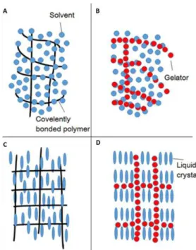
Liquid crystalline chemical gels are formed by in situ polymerization of monomers that can or cannot be liquid crystals with reactive groups in inert liquid crystal solutions. LC physical gels arise from the self-assembly of a fibrous low molecular weight structure (gelator) that imprisons the liquid crystal. The transition of sol-gel of the gelator and the isotropic-anisotropic transition of the liquid crystal occur in the gel formation process. [45] Figure 1.5 shows the illustration of physical and chemical gels as well as of the physical and chemical liquid crystal gels.
Liquid crystalline gels can be thermoreversible and have phase transitions: isotropic liquid-isotropic gel and isotropic gel-liquid crystalline gel that are independent of each other but dependent of the temperature. [45]
9 Diana Paiva Dissertação de Mestrado em Engenharia Biomédica
Figure 1.5 – Illustration of: a) chemical gels; b) physical gels; c) crystalline chemical gel; d) Liquid-crystalline physical gel. Adapted from [45].
3.1. Hydrogels:
Hydrogels are hydrophilic polymer networks that are capable of swell and adsorb water in a quantity higher than its weight. They present a physical structure similar to a biologic cellular matrix and can be used to modulate and study the cellular behaviour and tissue morphogenesis. Furthermore, hydrogels are suitable for a wide range of biomedical applications: 3D matrices for tissue engineering, drug delivery systems, injectable fillers for minimally invasive surgeries and composite biomaterials. [47]
Physical and chemical hydrogels are distinguished by the definition applied to gels (see physical and chemical gels). When the variation of physical condition such as pH, temperature, ionic strength or application of external forces occurs, the hydrogel may disintegrate and dissolve. [48]
10 Diana Paiva Dissertação de Mestrado em Engenharia Biomédica
hydrogels. [51] NCC, which have higher degree of crystallinity, surface area and pore volume are used to produce hydrogels and are gelated with, for instance, the addiction of certain polysaccharides. [52] Others examples of NCC hydrogels can be found in the literature. For example, the NCC are gelated with polymers, as polyethylene glycol and poly(methyl vinyl ether-co-maleic) acid, to produce hydrogels with enhanced physical properties. [50] In another research, NCC were incorporated into hydrogels based on cyclodextrin/polymer inclusion and these hydrogels, can possibly be used as a controlled drug delivery vehicle. [34]
Collagen hydrogels are easy to handle, although they present weak mechanical properties and non-controllable swelling. Concentrated collagen hydrogels were studied to surpass these disadvantages and it was shown that the hydrolysis of the gel was retarded comparing to collagen gels. Furthermore, they favour cell growth and do not contract drastically, making them suitable for dermal substitution. [53]
Elastomeric hydrogels are being developed by Betre et al., for biomedical applications due to its elasticity similar to skin, blood vessels, lungs and muscle. These gels are prepared from a
mixture of α-elastin with polycaprolactone (PCL) that stimulate chondrocyte adhesion and
proliferation. Chondrocytes were implanted in a collagen, alginate and K-elastin composite and the cartilage formation was observed. [54][55]
4. Polyvynil Alcohol (PVA):
PVA is a synthetic polymer that is widely used due to its biocompatibility and ability to produce macroporous hydrogels suitable for tissue engineering [56] and drug delivery systems [57]. PVA has good elastic and mechanical properties, such as tensile strength, and it can be dissolved in water. [57] Hydrogels of PVA and NCC were reported by Abitbol et al. and are formed by cyclic freezing and thawing. This method allows the formation of hydrogels with good stability at room temperature and prevents toxicity derived from PVA. These hydrogels present a similar water content of the biological tissues, have good elasticity and are thermoreversible at 50°C. [58] The crystallites formed in the freeze cycles act as a cross-linking agent forming a hydrogel with a pure crystalline network.
11 Diana Paiva Dissertação de Mestrado em Engenharia Biomédica
5. Cell adhesion mechanisms:
5.1. Protein adsorption:
To occur cell adhesion, firstly there has to exist protein adsorption by the biomaterial’s surface. A monolayer of proteins is able to adhere on the biomaterial shortly after the first contact protein-biomaterial. This monolayer is fundamentally responsible for cell adhesion and for a positive response of the body to an implanted biomaterial or, in case of scaffolds, cell proliferation. [49]
The cell membrane possesses integrins, which are receptors that bind to specific protein types. The proteins that enhance cell adhesion differ from cell line to cell line. As an example, fibronectin improves cell adhesion in fibroblasts but the contrary is shown with endothelial cells. Albumin is also known to decrease cell adhesion in fibroblasts and vitronectin enhances the adhesion of endothelial cells. Protein absorption is a competitive process and thus, concentration of different proteins should be taken into account in the culture medium. [49]
The proteins’ size, charge, structure stability and unfolding rate are some of the properties that influence the interaction with the material’s surface. For instance larger proteins, or proteins with a higher unfolding rate and even less stable proteins have more binding sites and thus lead to a more efficiently cell adhesion. Proteins near the isoelectric point, (the pH at which the molecule exhibits zero charge), have a better cell adhesion rate. [61]
Several studies also show that hydrophobic surfaces can more easily irreversibly bound to proteins due to the protein unfolding on the surface. At low ionic strengths, cationic proteins bind to anionic surfaces, as well as anionic proteins bind to cationic surfaces. These protein preferences are due to the ion-ion coulombic forces. [62]
The cell adhesion process is also influenced by surfaces with textures, which extends its surface area, heterogeneity and chemical composition of the surface. [61]
In contrast, the osmotic repulsion, dehydration between protein-surface, chain compression and protein hydrophobic exposure opposes to protein bounding. Van der Waals forces and desorption of water molecules also favour the protein-surface adhesion. [49]
In conclusion, protein adsorption is a complex mechanism and it is still being studied. The main reason for a biomaterial resist to protein adsorption relies on the retention of bound water by the surface molecules.
5.2. Non-fouling biomaterials:
12 Diana Paiva Dissertação de Mestrado em Engenharia Biomédica
applications such as implanted devices, urinary catheters, diagnostic assays, biosensors, affinity separations, microchannel flow devices, intravenous syringes and tubing. In a non-biomedical field non-fouling materials are used as biofouling-resistant heat exchangers and ship bottoms. [49] They are also used in in vivo nanoparticle-based diagnostics and microarrays. Currently, few
non-fouling materials can be used in biomedical applications without suffering any kind of degradation such as PEG, phosphorylcholine (PC) and sulfobetaine methacrylate (SBMA) and carboxybetaine methacrylate (CBMA). [63]
5.3. Improvement of cell adhesion in non-fouling materials:
For tissue engineering purposes, good protein adhesion to the materials or surfaces are essential. Hence, several physical (etching, roughening and photolithographic techniques) [64] and chemical (cross-linking of polyelectrolyte multilayer films [64], addition of RGD peptide [65], oxidation, fluorination and silanization [49]) methods have been developed to improve cell adhesion in biomaterials.
6. Fibroblasts: a cell culture perspective.
6.1. Fibroblasts:
Fibroblasts are mesenchymal cells responsible by production of growth factors and the main components of the extracellular matrix such as, interstitial collagens, proteoglycans, glycoproteins, cytokines, and proteases. [66] They are part of the connective tissue family, which also includes cartilage (chondrocyte) and bone (osteoblast and osteocyte) cells. They are found dispersed through the connective tissue of an organ and repair the human tissue by migrating to the wounded site and then excrete the extracellular matrix. [67]
13 Diana Paiva Dissertação de Mestrado em Engenharia Biomédica
Figure 1.6 – Illustration of the connective tissue cell family. The fibroblasts can in certain conditions of extracellular matrix, growth factors, cell shape and hormones differentiate in other cells of the connective
tissue family. Adapted from [67].
Recent studies also showed that fibroblasts have an important role in the angiogenesis process. [72] Furthermore, researches concluded that fibroblasts can differentiate into endothelial cells as well as, endothelial cells can differentiate into fibroblasts. This recent discovery opened new possibilities for in situ tissue repair. [73]
6.2. Fibroblasts in tissue engineering:
In 1975, the first techniques to culture fibroblasts were established by Rheinwald and Green with 3T3 murine fibroblasts. Fibroblasts are vastly used in cell culture on account of its individual behaviour (they do not form clusters) and the ability to adhere to plastic surfaces. In specific, dermal fibroblasts can be easily expanded from a small skin sample without refined purification methods, by enzymatic degradation or explant culture. For fibroblasts to grow there is no need for growth factors and one culture expand rapidly (24-72 hours) in the presence of serum. [74]
As previously mentioned, fibroblasts are able to migrate to injury sites and to differentiate into another connective tissue lineage cells, including bone, cartilage and adipose cells. Based on these unique properties, numerous studies were carried out until today focusing in fibroblasts and their potential in tissue engineering.
14 Diana Paiva Dissertação de Mestrado em Engenharia Biomédica
conducted investigations regarding implantable arterial grafts obtained by entrapment of human dermal fibroblasts in fibrin. Their team created grafts with similar aorta’s retention strength. [81] Co-culture of bone marrow fibroblasts and endothelial cells in polycaprolactone substrates showed good results for bone tissue engineering. [82]
6.3. Fibroblasts and liquid crystalline structures:
Fibroblasts were already used with liquid crystalline materials, demonstrating the importance of the liquid crystals in new therapies based in tissue engineering techniques.
Fibroblasts were successfully cell cultured in collagen type I gels with liquid crystalline textures. Furthermore, after one month of incubation, the number of fibroblasts is approximately the same as estimated in the connective tissue. [27] Kirkwood et al., as previously described in these chapter, observed the directional growth of fibroblasts according to the chiral nematic phase of the type I collagen gels, opening new perspectives in recreating the original connective tissue textures in vitro, for posterior tissue engineering purposes. [26]
15 Diana Paiva Dissertação de Mestrado em Engenharia Biomédica
Chapter II - Materials and Methods
1. Nanocrystalline Cellulose gels:
1.1.
Materials:All materials were used as received unless stated otherwise. Microcrystalline cellulose, Avicel® PH-1010, 50 m particle size, was purchased from Sigma-Aldrich. Sulfuric Acid (95-97%,
p.a) was used in the acid hydrolysis reaction of cellulose and was purchased from Merck. Glycerol (pharmaceutical grade) was purchased from Laborspirit and polyvinyl alcohol (95%, Mw=95000
g/mol) was purchased from Acros Organics. Dilutions were always performed using ultrapure water from a Millipore Elix Advantage 3 purification system. Collagen, from bovine Achilles tendon, was purchased from Sigma-Aldrich (St. Louis – USA). Glacial acetic acid (99.7%, p.a.) and ammonia (25%, p.a.) were purchased from Panreac. Yellow food dye was supplied by Globo.
Cryopreserved Human Neonatal Dermal fibroblasts (HNDF) were purchased from ZenBio. Modified Eagle Medium (DMEM), with 10% fetal bovine serum (FBS), the essential culture medium was acquired from Dulbecco’s. The solution of 0.25% trypsin/2.21 mM EDTA (ethylenediamine tetraacetic acid) were purchased from Gibco. FBS was supplied by EC approved origin, LDA. Resazurin (resazurin sodium salt at 0.1 mg/mL) was purchased from Sigma-Aldrich. Phosphate-buffered saline (PBS) was prepared at INEB by a laboratory technician.
1.2.
Acid hydrolysis of cellulose:16 Diana Paiva Dissertação de Mestrado em Engenharia Biomédica
centrifuge at 14000 rpm for an hour in order to concentrate the suspension. The resulting suspension was placed in a Spectra/Por® 4 cellulose membrane (from Spectrum), with a cut-off of 12-14 KDa, and dialyzed against ultrapure water until a constant pH value was achieved (normally ~5.5 to 6.0). [84]
The amount of NCC in a given suspension was controlled by gravimetric study (10 measurements). In this procedure small quantities of NCC suspension were dry, on an oven at 60 ºC, until constant weight. Higher contents of NCC in a suspension could be obtained by centrifugation. All suspensions were sonicated, with an ultrasonic processor UP400s (400W, 24kHz, Hieslcher Ultrasonics GmbH), prior to use.
Pictures of NCC suspension’s birefringence, observed by placing the suspension vial
between two cross polarizers sheets (from Edmund Optics), were acquire by using a Casio EX-F1 Exilim Pro camera. A light source was used behind the vial.
1.3.
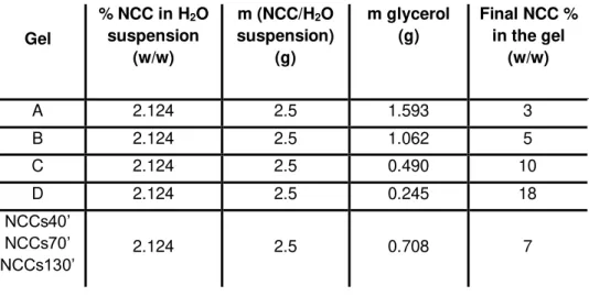
NCC/glycerol gel formation:Gelation was performed according to Dorris et al. procedure. [87] Typically glycerol was added to the NCC suspension and the mixture was stirred vigorously for about 30 minutes or until a homogeneous suspension was achieved. Then the mixture was placed in an oven at 60ºC until almost all the water is evaporated. The evaporation of the water was controlled by gravimetric method, this is, until constant weight. The NCC/glycerol ratio was adjusted by changing the amount of glycerol added to the NCC suspension. For instance, to obtain a gel with 5% (w/w) of NCC, to 5g of 2.5% (w/w) NCC suspension 2.5g of glycerol was added and this ratio was used for further concentration calculations. Gels with different NCC contents were obtained and are summarized in table 2.1.
Table 2.1 – Amount of NCC and glycerol used in the NCC/glycerol gels preparation. Final NCC content in the gels (value rounded to the integer).
Gel
% NCC in H2O suspension (w/w) m (NCC/H2O suspension) (g) m glycerol (g)
Final NCC % in the gel
(w/w)
A 2.124 2.5 1.593 3
B 2.124 2.5 1.062 5
C 2.124 2.5 0.490 10
D 2.124 2.5 0.245 18
NCCs40’
NCCs70’
17 Diana Paiva Dissertação de Mestrado em Engenharia Biomédica
To distinguish the gels with different hydrolysis times, the following nomenclature will be used through the study of the NCC/glycerol gels with 7% (w/w) of NCC in their composition:
NCCs40’: gels containing NCC with 40’ sulphuric acid hydrolysis time;
NCCs70’: gels with 70’ NCC sulphuric acid hydrolysis time;
NCCs130’:gels with 130’ NCC sulphuric acid hydrolysis time.
The remaining concentrations of NCC in the NCC/glycerol gels do not follow any specific nomenclature.
1.4.
NCC/PVA gel formation:Gels of NCC and PVA were prepared according to Abitbol et al. by cyclic freezing and thawing. PVA was dissolved in a ratio of 15g of PVA to 100g of water. After complete dissolution, the aqueous suspension of NCC was added to this mixture and left under stirring for 24 hours. The resultant suspension was placed in an oven at 90ºC during 6 hours proceeded by 24 hours of stirring at room temperature. 5 freeze-thawing cycles were performed to the sample. The freeze cycle lasted 18 hours at -18 ºC and the thawing cycle 4 hours at room temperature. To study the most viable gel for cell culture, gels with different NCC/PVA ratios (table 2.2) were prepared. [58]
Table 2.2 – Amount of NCC and PVA used in the NCC/PVA gels preparation. Final NCC content in the gels.
Gel % NCC in H2O
suspension (w/w)
m (NCC/H2O suspension)
(g)
m PVA (g) m H2O (g) NCC % of dry
weight of PVA
A 2.124 2.833 0.604 1.256 10
B 2.124 0.304 1.000 6.370 0.65
C 2.124 2.354 1.038 4.617 4.85
2. Collagen gels formation:
2.1. Gel formation:
18 Diana Paiva Dissertação de Mestrado em Engenharia Biomédica
3. Characterization of the Nanocrystalline cellulose and its
gels:
3.1.
Fourier Transform infra-red spectroscopy (FTIR):Dry samples of NCC, as thin films, were analyzed by FTIR. Thin films of NCC suspensions were casted onto polystyrene molds by solvent casting methods. NCC films were analyzed at Cenimat|I3N by a FTIR Thermo Nicolet 6700 spectrometer coupled with an attenuated total reflectance (ATR) sampling accessory (Smart iTR). ATR-FTIR spectra were recorder with an incident angle of 45º, from 4000-600 cm-1, with 4 cm-1 resolution, 32 scans at room temperature.
ATR-FTIR spectra of the NCC gels, before and after exposure to cell culture medium, were acquired at INEB with a Perkin-Elmer 2000 system 2000 XR-analysis.
3.2.
X-Ray Diffraction:The structural analysis of NCC and microcrystalline cellulose was achieved by collecting X-Ray Diffraction patterns. This was done using a XRD PANalytical (model X’Pert Pro) in Bragg– Brentano geometry with Cu K⍺line radiation (λ=1.5406 Å) at 45 kV and 40 mA, the instrument being equipped with an X’Celerator detector. The XRD patterns were collected with a scanning step of 0.0334° over the angular 2θ range 10°–40°, with a total acquisition time of 4 min. To analyze the diffractograms, specific software (OriginPro 8) was used that allows the characterization of the peak parameters such as position, intensity, width and shape.
3.3.
Scanning Electron Microscopy (SEM):19 Diana Paiva Dissertação de Mestrado em Engenharia Biomédica
Figure 2.1– Schematic diagram of a Scanning electron microscopy (SEM) device. Adapted from [88].
Non-conductive materials have to be coated with a thin, electrically grounded layer of metal such as gold or by a non-metal as carbon. This layer diminishes the negative charge of the electron beams irradiating the sample’s surface. The coating procedure has some disadvantages: at higher magnifications the image may be from the metal instead of the sample and if the layer’s thickness is more than 200 Å, the electron beam may not reach the material in an EDS analysis. [49]
SEM (Zeiss Auriga at CENIMAT|I3N), was used to study the size and shape of nanocrystalline cellulose obtained at different acid hydrolysis times. An electron beam with 2Kv was applied to the samples with an aperture size of 30 µm. An aqueous suspension of NCC was
placed in circular transmission electron microscopy (TEM) grids. The water of the sample was completely dried at room temperature and coated with carbon (thickness layer 20 nm). The lengths and diameter of individual nanoparticles, observed in the SEM images, were measured using ImageJ software (version 1.48, http://imagej.nih.gov/ij/)). The distribution of the particles length and width were achieved with 100 measurements.
3.4.
Polarized Optical Microscopy (POM):20 Diana Paiva Dissertação de Mestrado em Engenharia Biomédica
second polarizer called analyser, absorbs almost all the light and only the beams that passed through an anisotropic environment are displayed, otherwise dark background is shown. A digital camera is used to record images of the samples and is placed above the objectives and the image is acquired by a semi-transmitting mirror. [89]
Figure 2.2 – Schematic of a polarized optical microscope. Adapted from [90].
Polarized optical microscopy was used to observe liquid crystalline textures in NCC/PVA and NCC/glycerol gels. To analyse the liquid crystalline phases a 90° difference between the analyser and the first polarizer had to be settled, this is, the image was acquire between cross polarizers. In the LC phase, the light is scattered according to the pitch of the sample and only the beams parallel to the analyser are observed. Optical microphotographs of the samples were taken using a transmission mode in an Olympus BX51 microscope coupled with an Olympus DP73 camera (CENIMAT|I3N) and Olympus BX50 at INEB. The pitch from the fingerprint texture observed in the acquired images was measured with the ImageJ software. The distribution of the pitch values was achieved with 100 measurements in each condition.
3.5.
Transmission electron microscopy (TEM):21 Diana Paiva Dissertação de Mestrado em Engenharia Biomédica
formed by transmission electrons, meaning, the electrons pass through the sample due to its thickness or transparency. The collision of these electrons with a fluorescent screen or a CCD generates the image. Black and white images are created. The black images occur when few electrons are transmitted. On the other hand, white images are created when a large number of electrons pass through the sample, thus are transmitted.
Figure 2.3 – Schematic diagram of a Transmission electron microscopy (TEM) device. Adapted from [88].
TEM enables the assessment of chemical compounds present in the sample and the crystallinity of the material. The sample preparation for TEM is a very complex procedure: the sample has to be completely dried due to the propagation of the electron beams and so vacuum was applied. Furthermore, the specimen has to be very thin so it has lower resistance to the electrons (“electron transparent”) and has to be resilient to the high energy electron beams. [92]
22 Diana Paiva Dissertação de Mestrado em Engenharia Biomédica
4. Integrity tests:
4.1.
Non-mobility test:After total removal of water from the NCC/glycerol gel, these were inverted and placed at rest during two weeks.
4.2.
PBS stability test:In order to understand the stability of the gels described in 1.3 was executed a simple test. The test consisted in placing 1ml of PBS, mixed with a yellow food dye, on top of a gel, placed in a vial. The set was closed and incubated at 37º C during six days. The test was performed in both NCC/glycerol and NCC/PVA gels. If the form and shape of the gels remain constant after this PBS stability test, a non-mobility test was conducted to the NCC/glycerol gels (see 4.1).
4.3.
pH and culture medium stability test:This test was carried out with the objective of increasing the pH of the NCC/glycerol gels to a suitable pH for cell culture and to ensure the stability of the gels after this procedure.
To increase the pH of the NCC/glycerol gels to a pH of 7, 1ml of PBS was deposited in the top of the gel and incubated at 37ºC for 4 hours and then the PBS was removed. The procedure was repeated four times, wherein the gel was left in the incubator overnight in the last procedure. The experimental work was performed in a 0.04% CO2 atmosphere incubator.
To determine the behaviour of the NCC/glycerol gels in cell culture medium as well as the pH of the gel after this treatment, 1ml of cell culture medium was added to the gel and the set was incubated at 37ºC during 24 hours in an atmosphere of 5% CO2. The same procedure was
repeated in a 0.04% CO2 atmosphere.
pH measurements were performed with a pH micro probe from Lazar Research laboratories, model PHR-146B, that can be observed in figure 2.4. Calibration of the equipment was executed previously to any measurements using the appropriate standard solutions.
23 Diana Paiva Dissertação de Mestrado em Engenharia Biomédica
Figure 2.4 – pH probe used to measure the pH of the gels during the pH integrity test.
4.4.
Swelling behaviour evaluation:
NCC/glycerol gels were submerged in PBS at 37ºC and weighted at precise time intervals. An attempt to remove the excess of water from the samples surface was done by placing the sample within filter papers.
5. Chemical analysis of the NCC/glycerol gels:
5.1.
Electro kinetic Analysis (EKA):24 Diana Paiva Dissertação de Mestrado em Engenharia Biomédica
6. Rheology
The rheological properties of the NCC/glycerol gels: NCCs40’; NCCs70’ and NCCs130’ were studied with a rotational rheometer, (Kinexus Pro, Malvern Instruments, Malvern, UK). A brief explanation of the theory behind the methodology used is described in the supporting information (Annex I). For both viscometry and oscillatory measurements, the samples were allowed to rest after loading, for at least 30 min, before start applying any deformation.
6.1.
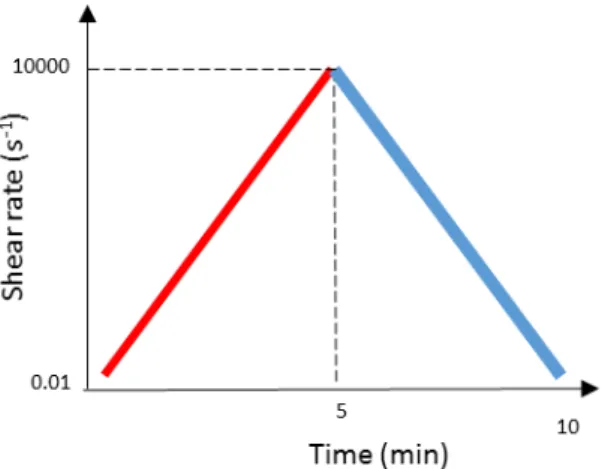
Viscometry measurements:Viscometry assays to the gels were performed using a cone (Ø 40 mm, 0.5°) and plate geometry, with a 0.015 mm gap and at 25°C, to assess the thixotropy of the gels through a hysteresis loop. This test was performed by means of an increasing ramp of shear rates (0.01 s -1– 10000 s-1), immediately followed by a decreasing ramp with the same shear rate values (Figure
2.5). The test was performed for a total of 10 minutes (5 minutes per shear rate ramp).
The dynamic shear viscosity of the samples could also be obtained from these assays. The area of the hysteresis loop is a measure of the thixotropic degree of the material, and depends on the experimental conditions such as test duration, maximum shear rate applied and shear history of the sample prior to the experiment. [95]
Figure 2.5 – Shear rate ramps applied to the sample for the hysteresis loop tests.
6.2.
Oscillatory measurements:25 Diana Paiva Dissertação de Mestrado em Engenharia Biomédica
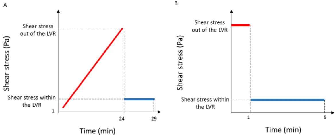
were performed from 0.01 Hz to 50 Hz to determine the behaviour of the material with the increasing of the frequency applied as described in the literature.[96] In addition, oscillatory stress sweeps from 1 Pa to 4000 Pa, immediately followed by an oscillation test with fixed frequency and stress within the LVR of the gels for 5 minutes, were conducted as represented in figure 2.6 - A. This stress sweep test was adapted according to Shona Pek at al., that studied the effects of a thixiotropic matrix to posteriorly use in mesenchymal cells [97]. With these assays, it was assessed the ability of the gel to return to its initial viscoelastic properties after a transition to a liquid state. Both the yield stress and the complex shear stress of each gel needed for a solid-liquid transition of the material to take place were also determined.
A test sequence was designed to study the ability of the gels to recover the solid like properties after being stressed with a high shear stress value (out of the LVR and that allows a solid-liquid transition) as performed by Sharma et al.[98] The sequence (Figure 2.6 - B) was repeated 15 times for each gel and consisted on applying a shear stress (out of the LVR) for 1 min, followed by the application of a different shear stress (within the LVR) for 4 min.
Figure 2.6 – Oscillatory assays performed to the gels. A - Oscillatory stress sweep, followed by an application of the LVR conditions. B - Oscillatory test in which a shear stress out of the LVR is applied for 1
minute followed by the application of a shear stress within the LVR for 4 minutes; this was repeated 15 times for each gel.
To study the differences of the viscoelastic properties of the gels after cell culture conditions (48 hours in cell culture medium), was used a fixed frequency and a fixed shear stress within the LVR of the gels, previously determined. The gel was placed in a gel caster (QGel® 3D disc casters (Lausanne, Switzerland) and incubated in the conditions described in section 4.3. After incubation, gel discs were cored out with a biopsy punch cylinder of 8 mm of diameter. For the oscillatory measurements, a parallel plate geometry (Ø 8 mm) was used with a 1.5 mm gap due to the use of the gel caster with the same diameter.


![Figure 2.3 – Schematic diagram of a Transmission electron microscopy (TEM) device. Adapted from [88]](https://thumb-eu.123doks.com/thumbv2/123dok_br/16537291.736591/43.892.334.579.234.662/figure-schematic-diagram-transmission-electron-microscopy-device-adapted.webp)