Engineering
ISSN: 1809-4430 (on-line)
_________________________
2 Universidade Estadual de Campinas/ Campinas - SP, Brasil.
APPLICATION OF OPTICAL METHOD IN MEASURING MECHANICAL VIBRATIONS IN A CANTILEVER BEAM
Doi:http://dx.doi.org/10.1590/1809-4430-Eng.Agric.v37n1p84-90/2017
MARCOS V. G. DA SILVA1*, INÁCIO M. DAL FABBRO2, ANTÔNIO C. L. LINO3
1*Corresponding author. Faculdade de Jaguariúna/ Jaguariúna - SP, Brasil. E-mail: [email protected]
ABSTRACT: The pertinent literature discloses a family of optical profile measuring techniques highlighting the moiré methods. The Moiré technique is based on the interference of two superimposed optical grids which produce fringe patterns which can be processed to analyze the DYNAMIC MEASUREMENT IN MATERIALS mechanical behavior. The goal of this research is to experimentally determine the mechanical displacement of a slim cantilever beam by means of Moiré technique with Phase Shift. Photomechanical experimental arrangement included a digital camera, a multimedia projector and a PC. The occurrence of oscillations has been adequately analyzed. The results showed data from which useful information can withdraw, being of great importance to support agricultural machinery projects and development.
KEY WORDS: Moiré Technique, Material Mechanical Behavior Analysis, Deformation, Strain, Agricultural Machinery.
INTRODUCTION
Stress and stress analysis is of common occurrence in a optimization of product development. More precise analysis test a particular element using experimental techniques (MAZZETI FILHO 2004). Strain-gages technique are frequently employed to obtain deformation as well as displacement measures, however they generate punctual data and no continuous fields, requiring many sensors conveniently distributed and positioned, which demands in increased cost and installation time (RI et al., 2010).
Profile-measuring techniques are frequently employed in generating the topography of mechanical components which can be associated to interferometry, as well as to solutions of statics and dynamical problems (GOMES et al., 2009).
Moiré techniques are based on optical interferometry, showing ability in determining displacement fields, however, the fringes should be spatially differentiated to generate deformation and stress fields. Advantages of moiré methods include certain advantages over similar techniques, as low sensitivity to external noises, presenting movement magnifying ability, require low cost experimental setup, generating fast measurement and suitable for large displacement (GLEICE et al., 2011).
Moiré phenomenon takes place when two optical grids of same mesh density are superimposed, generating wave like patterns named moiré fringes (SILVA, 2011).
These fringes are generated by the shadow moiré technique as well as by the projection moiré method (PORTO et al., 2011). In the shadow moiré technique, the optical grid is projected onto the testing object surface, generating the second grid in real time (GAZZOLA et al., 2012). Phase shifting technique grids out of phase by 90o are projected onto the objected surface, generating interference. In that case the fringes are visualized after adequate image processing (SILVA et al., 2012).
The pertinent literature discloses many references on the application of moiré methods
in studying stress-strain solutions. MAZZETI FILHO et al. (2004) reported a complete displacement field in sugar cane cutting discs. ALBIERO et al. (2012) reported the determination of an isodeformation map of bamboo specimens by means of moiré methods applied to compression tests. GAZZOLA et al. (2010) reported the determination of a qualitative stress-strain map of a wooden beam subjected to torsional loading.
VIEIRA (2006) reported a vibrational analysis of a cantilever beam with the application of the shadow moiré technique, determining the transversal displacement of the elastic line previewed in the Euler-Bernoulli beam theory by applying a modal analysis. That method allowed an instantaneous visualization of the moiré fringes, as well as the displacement on the beam.
This research intended to study the application of the moiré method with phase displacement in order to determine the displacement field of cantilever beam under controlled vibration.
MATERIAL AND METHODS
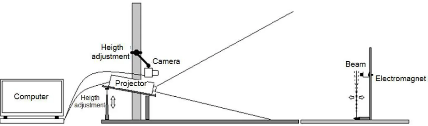
The experimental part of this research was carried out in the Laboratory of Optics in the Faculty of Agricultural Engineering at the State University of Campinas, as well as at Agricultural Institute of Campinas in Jundiai, SP. The experimental setup as shown on Figure 01 included a PC, a NEC/VT560 LCD projector, a SAMSUNG/SDC-312 CCD camera, a SAMSUNG/SH-HMX20C movie camera, and a UDB1000 DDS with a range of 1 to 60 MHz to feed the solenoid with different wave patterns and frequencies.
A phase shifting moiré technique was employed to obtain the deformation mapping of the slim beam movement.
FIGURE 1. Proposed experimental setup.
Image processing was carried under the support of the software ImageJ and Idea which were associated to routines which permitted the creation of a methodology able to generate three dimensional digital models with dynamic analysis.
The tested specimen was represented by a 300 mm long by 30 mm wide and 1mm thick steel piece, clamped at one of its end, here considered as a cantilever beam which was painted with white opaque color to improve the contrast with the projected grid. Four sinusoidal grids out of phase by ¼ of period were projected onto the testing body having their images captured by the camera. These images were considered as reference planes.
These four image groups were then submitted to the IDEA software in order to obtain
the beam topography at each moment of the beam deformation. Due to the intrinsic program characteristics, the quota of each point of the beam is given in radians.
A second test was carried in slow motion, capturing the images at a rate of 300 frames s-1, enabling a better analysis of the beam displacement map.
Unlike the results reported by VIEIRA (2006), the slim beam of this study has been kept in equilibrium position in which the nodes were not revealed due to the low exciting frequency. Beyond that, the proposal of this research was solely to identify the laminar line displacement.
The analysis reported by VIEIRA (2006) was supported by the shadow moiré technique where the nodes were detected through the fringes frequency, meanwhile, the method employed by this research relayed on the profile generated by the multiplication of fringes, differing, that way, from shadow moiré method. The phase shifting technique allows a multiplication factor of four times generated by a unique grid, in which the out of phase angle is of 90o by phase.
RESULTS AND DISCUSSION
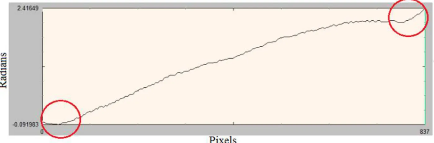
The deformation at the beam border exhibited similar abnormality as reported by MAZZETI FILHO (2004) which used the shadow moiré method and LINO (2008) which used the phase shift projection moiré method, as shown on Figure 02 highlighted by a red circle.
FIGURE 2. Border abnormalities exhibited by the testing beam.
LINO (2008) comments that the application of Gaussian filter to digital images generated the border abnormality, suggesting the application of the Fourier transform to avoid such occurrence. However, the Fourier transform filtration to correct this anomaly requires a very long computational time, turning unfeasible in the present case due to the large number of images to be processed.
However, another possible solution consists in selecting an area, larger than the effective beam area, as it can be observed on Figure 03, applying the Gaussian filter and cutting the extra area, excluding the defective border, as observed on Figure 04 with no alteration of the original length i.e., 837 pixels, as it is also observed on Figure 02.
FIGURE 4. Border defects minimization.
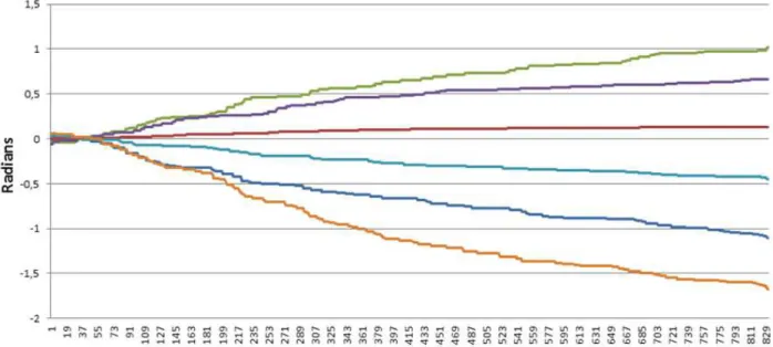
Image processing was carried after the correction of border effects, facing, however, the limiting value of 30 frames s-1 imposed by the CCD camera enabling the system of capturing six beam displacements holding a sampling rate of 5 Hz, observing that the oscillating cycle was repetitive which was independent of the time interval required to capture the beam movement.
FIGURE 5. Displacement of the testing cantilever beam obtained through the moiré technique.
TABLE 1. Displacement of testing beam vibration by a square wave input of a frequency of 5Hz.
Time
(sec) Displacement
(Δt) (rad) (mm)
1 1.02 15.28
2 0.66 10.00
3 0.13 1.30
4 -0.45 -6.74
5 -1.10 -16.47
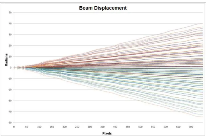
values results obtained from the moiré technique. Figure 06 shows the identification of 60 displacements generated from the same Hz frequency square wave, however with new calibration.
FIGURE 6. Beam displacement obtained by the Moiré technique.
Displacement numerical values were obtained with the support of the Idea software by drawing a medium line along the beam length, as represented on the Figure 07. Later, line values were converted into coordinate values and transferred to the applicative EXCEL for graphical representation and conversion to scalar quantities.
FIGURE 7. Beam topographical elevation model showing a midline selection.
FIGURE 8. Displacement in function of time.
Note in Figure 9 that the displacement of the fringe, is highlighted and denotes the displacement at the time which the projected grid dephased 90 degrees each, allowing visualization of 8 fringes at each displacement. Thus obtaining a total of 32 fringes to the final result, providing a higher definition of the sample captured by the camera.
FIGURE 9. Fringe displacement in relation to the stage.
VIEIRA (2006) reported the results of another research carried out on a beam of 50 mm length vibrating at a frequency of 29.36 Hz, being possible to identify 24 fringes by means of a shadow moiré technique using grid density of p = 1.55 lines mm-1. This research also presents the
results of tests carried on a beam of 30 mm length using a p = 0.07 lines mm-1 mesh density grid, demonstrating that exists higher effectiveness of the projection technique with phase displacement, observing that with a smaller number of grid lines a larger number of fringes in a smaller testing body, generating higher precision in determining the beam topography and displacement.
REFERENCES
ALBIERO, D.; ARAUJO, M. C.; FERRAZ, A. C. O.; DAL FABBRO, I. M.; MACIEL, A. J. S. Moiré optical technique for evaluation of cashew nuts (Anacardium Occidentale, L.) isostrain. varia. Scientia Agrarias, Cascavel, v. 9, n. 2, p. 9-20, julho, 2012.
GAZZOLA, J.; DAL FABBRO, I.M.; SORIANO, J.; ENES, A.M.; KUNINARI, F.; Shadow moiré
applied to torsional stress distribution mapping. Agricultural Engineering Journal. Sophia, v. 48, n.2, p. 61-65. Oct. 2010.
GAZZOLA, J., DAL FABBRO, I.M., SORIANO, J., SILVA, M. V. G., RODRIGUES, S. Photomechanical analysis of wooden testing bodies under flexural loadings. Engineering and Technology, Istanbul, v. 70, p. 396-401, outubro, 2012.
GLEICE, C. A.; YANAGY Jr., T.; SILVA, E.; BRAGA Jr., R. A.; CAMPOPS, A. T. Recuperação de topografia de ovos por meio da técnica de moiré e calibração independente. Engenharia
Agrícola. Jaboticabal, v. 31, n. 2, p. 211-218, mar./abr, 2011.
GOMES, T. S.; BRAGA JR., R. A.; LINO, A. C. L.; RABELO, G. F., COSTA, R. M. Calibração da técnica de moiré aplicada a perfilometria de protótipos mecânicos. Revistas Ciência e
Agrotecnologia. Lavras, v. 33, n. 2, p. 574-579, mar./abr., 2009.
MAZZETI Filho, V. Utilização da interferometria de moiré no estudo de tensões dinâmicas em
discos flexíveis. 115 p. Dissertação de Mestrado em Engenharia Agrícola – Faculdade de Engenharia Agrícola, Universidade Estadual de Campinas, 2004.
PORTO, F.; GURGEL, J. L.; FARINATTI, P, T, V. Topografia de moiré como método de
avaliação postural: revisão do estado da arte. Revista Brasileira de Geriatria e Gerontologia. v. 3, n. 14, pp. 567-577, 2011.
RI, S.; FUJIGAKI, M.; MORIMOTO, Y. Sampling moiré method for accurate small deformation distribution measurement. Experimental Mechanics. v. 50, n.4, p. 501-508, 2010.
SILVA, M. V. G., GAZZOLA, J., DAL FABBRO, I. M., LINO, A. C. L. Topographical image transference compatibility generated through moiré technique applying parametrical softwares of
computer assisted design World Academy of Science. Engineering and Technology. v.70,
p.391-395, 2012.
SILVA, M. V. G. Determinação das dimensões espaciais de corpos sólidos por Técnicas de
Moiré. 76 p. Dissertação de Mestrado em Engenharia Agrícola – Faculdade de Engenharia
Agrícola, Universidade Estadual de Campinas, 2011.
VIEIRA, M. A. P. Análise vibracional de viga engastada utilizando a técnica de moiré: um
estudo de caso. Dissertação de Mestrado. UNICAMP Junho de 2006.