Faculdade de Engenharia
Analysis of morphing, multi-stable structures actuated by
piezoelectric patches
Pedro Miguel dos Santos Carvalho Portela
Licenciado em Engenharia Mecˆanica
pela Universidade do Porto, Faculdade de Engenharia
Disserta¸c˜ao submetida para satisfa¸c˜ao parcial
dos requisitos do grau de
Mestre em Engenharia Mecˆanica
Disserta¸c˜ao realizada sob a orienta¸c˜ao de Professor Doutor Pedro M. P. R. C. Camanho
do Departamento de Engenharia Mecˆanica e Gest˜ao Industrial
Professor Doutor Ian Paul Bond
do Departamento de Engenharia Aeroespacial da Universidade de Bristol
por
Pedro Miguel Portela
Submetido ao Departamento de Engenharia Mecˆanica e Gest˜ao Industrial em Julho de 2005, para satisfa¸c˜ao parcial dos requisitos na obten¸c˜ao do grau de
Mestre em Engenharia Mecˆanica
na Universidade do Porto, Faculdade de Engenharia
Resumo
As estruturas de geometria vari´avel, estruturas m´orficas, adaptam activamente a sua forma reagindo a solicita¸c˜oes exteriores ou simples-mente por forma a aumentar o seu rendimento. As superf´ıcies de con-trolo existentes actualmente em aeronaves comerciais s˜ao necess´arias para manter o seu controlo e estabilidade mas n˜ao podem ser consid-eradas estruturas m´orficas. Alguns exemplos de estruturas m´orficas consistem em asas com varia¸c˜oes de ˆangulo de varrimento, incidˆencia e dihedro. Estas aplica¸c˜oes muito espec´ıficas e, essencialmente, do dom´ınio da avia¸c˜ao militar combinam estruturas articuladas r´ıgidas com actuadores ”cl´assicos” do tipo hidr´aulico, pneum´atico ou elec-tromagn´etico para efectivar as mudan¸cas de forma. A pesquisa e investiga¸c˜ao actual est´a a focar a sua aten¸c˜ao em combina¸c˜oes de ac-tuadores feitos com materiais activos, do estilo piezoel´ectricos, magne-toestrictivos e ligas de mem´oria de forma, com estuturas e mecanismos complacentes. Esta combina¸c˜ao, quando bem conseguida, permite au-mentar a fiabilidade e diminuir o consumo energ´etico dos actuadores ao mesmo tempo que reduz drasticamente o seu tamanho. O ponto fraco reside nas estruturas subjacentes que normalmente tˆem uma capacidade de carga muito reduzida.
Este trabalho explora a possibilidade de criar estruturas m´orficas com-binando estruturas multi-est´aveis com um tipo especial de actuador piezoel´ectrico. Este conceito foi estudado no passado por investi-gadores da Virginia Polytechnic Institute and State University. Foi efectuado um esfor¸co adicional para produzir um modelo de elemen-tos finielemen-tos que permitisse perceber melhor os fen´omenos associados. A flexibilidade do M´etodo dos Elementos Finitos permitiu tamb´em testar uma grande variedade de configura¸c˜oes e assim escolher a mais eficiente. Os resultados obtidos foram verificados experimentalmente atrav´es da produ¸c˜ao de um laminado comp´osito assim´etrico bi-est´avel accionado por um actuador piezoel´ectrico.
Orientadores:
Dr. Pedro P. Camanho Universidade do Porto Dr. Ian Paul Bond University of Bristol
by
Pedro Miguel Portela
Submitted to the Department of Mechanical Engineering and Industrial Management
in July 2005, as partial fulfillment of the requirements for the degree of Master in Mechanical Engineering
at the University of Porto, Faculty of Engineering
Abstract
Morphing or shape changing structures can actively modify its ge-ometry in order to better adapt to exterior loading or to increase performance. Control surfaces in today’s aircrafts are necessary for a controlled flight and cannot be considered as morphing structures. Previous designs of morphing aircraft structures include wings with variable sweep, incidence and dihedral angle. These designs combined stiff structures with mechanisms and powerful actuators to perform the desired shape change. Current research is focusing on combina-tions of active materials such as piezoelectric materials, magnetostric-tive materials and shape memory alloys with compliant structures and mechanisms to achieve macro scale geometric changes. These combi-nations, when successful, allow for an increase e reliability, a reduction in power consumption as well as in actuator size. The problem areas are usually the underlying compliant structures that have a reduced load carrying capability.
This work explores the possibilities of creating a morphing structure using multi-stable structures combined with a piezoelectric actuator. This concept has been tested in the past by researchers in Virginia
Polytechnic Institute and State University. Considerable effort was
put here on the accurate Finite Element Modelling of such structures in order to better understand the underlying physics and to be able to design such structures. Experimental measurements and tests were performed on both the bi-stable laminates and on the morphing plate that was manufactured.
Supervisors:
Dr. Pedro P. Camanho University of Porto Dr. Ian Paul Bond University of Bristol
par
Pedro Miguel Portela
Pr´esent´ee au D´epartement de Genie Mechanique et Gestion Industrielle en julliet 2005, comme accomplissement partiel des exigences pour le degr´e de
Maˆıtre en Inginerie M´ecanique
Resum´
e
Les structures de g´eom´etrie variable, structures morphiques, adaptent activement sa forme en r´eagissant aux sollicitations ext´erieurs ou, plus simplement, de fa¸con `a augmenter sa performance. Les surfaces de contrˆole qu’on trouve actuellement dans les avions commerciaux sont n´ecessaires pour maintenir son contrˆole et stabilit´e, mais ne peu-vent pas ˆetre consid´er´es structures morphiques. Quelques exemples d’estructures morphiques sont les aigles avec des variations d’angle de balayage, incidence et di´edre. Ces applications tr`es sp´ecifiques et essentiellement du domaine de l’aviation militaire combinent des structures articul´ees rigides avec des actuateurs ¿ classiques À de
type hydraulique, pneumatique ou ´electromagn´etique pour r´ealiser les changements de forme. L’investigation actuelle fait attention aux combinassions de actuateurs fait a partir des mat´eriaux actifs, comme des mat´eriaux pi´ezo´electriques, magn´etostrictifs et avec m´emoire de forme, avec des structures et m´ecanismes accommodantes. Cette com-binaison, si bien accompli, permet de augment la fiabilit´e et diminuer la consumation ´energique des actuateurs au mˆeme temps que r´eduit sa taille drastiquement. Les probl`emes se trouvent au niveau des struc-tures subjacentes que ont normalement une capacit´e de charge tr`es r´eduite. Ce travail explore la possibilit´e de d´evelopper des structures morphiques en combinant des structures multi stables avec un type sp´ecial d’actuateur pi´ezo´electrique. Ce concept a ´et´e ´etudi´e par des investigateurs de la¿Virginia Polytechnic Institute and State
Univer-sity À. Un effort suppl´ementaire a ´et´e fait pour produire un model de
El´ements Finits que permettait de mieux comprendre les ph´enom`enes associ´es. La flexibilit´e de la m´ethode des El´ements finits a permit de essayer une grande vari´et´e de configurations et choisir la plus effi-ciente. Les r´esultats obtenus ont ´et´e v´erifi´es exp´erimentalement a travers de la production d’un lamin´e composite asym´etrique bistable activ´e par un actuateur pi´ezo´electrique.
Superviseurs:
Dr. Pedro P. Camanho University of Porto Dr. Ian Paul Bond University of Bristol
I would first like to express my gratitude to my supervisors, Dr. Pe-dro Camanho from the Universiy of Porto, Dr. Ian Bond and Dr. Paul Weaver from the University of Bristol for their encouragement, support and for giving me all the conditions both at the University of Bristol, where most of the experimental work was performed and at the University of Porto, where most of the analysis part of the project was done.
I would also like to thank Dr. Kevin Potter from the University of Bristol for introducing me to the world of asymmetrical laminates and for helping me in the manufacturing and testing of some specimens. A special thanks to the staff and post-graduate students of the Aerospace Engineering Department of the University of Bristol for making me feel at home away from home. I also wish to thank my fellow co-workers and friends at the Department of Mechanical Engineering of the University of Porto and at INEGI, Porto for their honest friend-ship and for being excellent team players.
To my parents, to whom I dedicate this work, I wish to acknowledge all that they did for me to get this far. To Carolina, for believing in me and for her constant support.
Finally, the financial support of the Portuguese Science Foundation (FCT) through the grant SFRH\BM \16199\2004 is gratefully ac-knowledged.
Resumo . . . iii
Abstract . . . iv
Resum´e . . . v
Acknowledgments . . . vi
1 Introduction and objectives 1 1.1 Motivation . . . 1
1.2 Bibliographical survey . . . 4
1.3 Multistable laminates . . . 13
1.3.1 Classical lamination theory at a glance . . . 13
1.3.2 Laminate thermal stresses . . . 18
1.4 Macro-Fibre composite actuators . . . 21
1.4.1 Piezoelectric effect and materials . . . 21
1.4.2 Macro Fibre Composite . . . 23
2 Initial Exploratory Investigation 27 3 Finite Element Simulations 33 3.1 Introduction and scope . . . 33
3.2 Modelling the curvature development . . . 34
3.2.1 Theory . . . 34
3.2.2 Model description . . . 36
3.2.3 Moisture effects and stress relaxation. . . 42
3.3 Modelling the snap-through event . . . 46
3.3.1 Theory . . . 46
3.3.2 Model description . . . 48
3.3.3 Discussion of results . . . 52
3.4 Modelling the piezoelectric actuator . . . 54
3.4.1 Theory . . . 54
3.4.2 Model description . . . 57
3.4.3 Modelling the actuation effect . . . 58
3.4.4 Discussion of results . . . 60
3.5 Additional FE Models . . . 66
3.5.1 Rectangular [0◦/90◦] slab . . . . 66
3.5.2 Combined [0◦/90◦] + [0◦/45◦] laminate . . . . 67
3.5.3 Chess board laminate . . . 68
3.5.4 Laminate with two MFC’s . . . 71
3.6 Conclusions . . . 71
4 Experimental results 73
5 Conclusions 77
6 Future Work 81
1-1 Depiction of how birds adapt their wing geometry for different
flight regimes. . . 2
1-2 The F14- Tomcat . . . 3
1-3 Flight profile, adapted from [1] . . . 3
1-4 Rockwell B-1B Lancer with variable sweep wings . . . 6
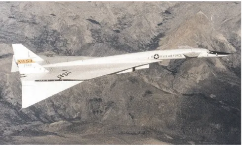
1-5 Valkyre XB-70 with rotating wingtips . . . 7
1-6 Classification of morphing aircraft technology, adapted from [2] . 8 1-7 Schematics of the Active Fibre Composite actuator . . . 11
1-8 The MFC patch actuator . . . 12
1-9 Schematics of a hollow piezoelectric fibre [3] . . . 12
1-10 Laminate coupling relationships . . . 18
1-11 Shapes obtained with CLT and with non-linear FEA. . . 20
1-12 Example of extreme shape change accomplished with an asymmet-rical laminate. . . 20
1-13 Polarization of piezoelectric crystals. . . 22
1-14 Piezoelectric strains. . . 22
1-15 Layers of an MFC actuator [4] . . . 24
1-16 MFC voltage versus strain characteristics. . . 25
2-1 Manufacturing of the plates. . . 27
2-2 Direction in which the MFC should be bonded. . . 28
2-4 The bi-stable laminate, the MFC patches and the adhesive before
bonding. . . 29
2-5 Vacuum bag used to cure the adhesive. . . 29
2-6 MFC patch bonded to the CFRP laminate. . . 30
2-7 Spring effect. . . 30
2-8 Two MFCs bonded to the laminate. . . 31
3-1 FE model boundary conditions . . . 35
3-2 Representation of the analysis steps used . . . 37
3-3 FE plot of the deformed plate at the beginning of the snap-through step. Scale factor=1 . . . 37
3-4 Definition of parameters used to calculate the curvature . . . 38
3-5 Definition of principal curvatures directions . . . 38
3-6 FE contour plots of the three principle curvatures for the three different lay-ups . . . 39
3-7 Comparison between FE shapes and those of the manufactured laminates. . . 40
3-8 Boundary conditions used on the [45◦/ − 45◦] T laminate models . 41 3-9 Solution failure if load maximum is reached . . . 47
3-10 The arc length method implemented in Abaqus . . . 47
3-11 FE plots of the two stables states for the three different laminates 49 3-12 Evolution of the applied load with the step increment . . . 49
3-13 Measured force versus displacement. Taken from [5] . . . 50
3-14 Measured force [5] versus displacement. . . 51
3-15 Maximum force versus plate length plot. Polynomial fit allows to extrapolate for shorter or longer plates . . . 52
3-16 Schematics of the solution proposed by Schultz . . . 55
3-17 Variation of the MFC’s elastic properties with temperature . . . . 55
3-18 Development of curvature during cool down. . . 56
3-20 FE mesh of the laminate and the active area of MFC patch after
the curing step . . . 59
3-21 Schematics of the insufficient actuation power . . . 60
3-22 Design tree of the FE models analyzed . . . 60
3-23 Typical LPF plot for a successful snap-through . . . 62
3-24 LPF curve for the T800 fibre with M8557 actuator . . . 62
3-25 Design curve of MFC actuated bi-stables plates . . . 63
3-26 LPF plot for the moistened AS4 fibre laminate with an M8557 actuator . . . 64
3-27 Contour plots of the strain field caused by the MFC . . . 65
3-28 Rectangular asymmetrical laminate. Pictures of the two stable states and the FE model. . . 66
3-29 Schematics of the two stable states. . . 67
3-30 The mixed laminate before and after snap-through. . . 68
3-31 Rectangular asymmetrical laminate. Pictures of the two stable states and the FE model. . . 69
3-32 Chess board laminate curvatures. . . 70
3-33 Laminate with two MFC bonded to each side. . . 71
4-1 Measurement of the critical loads. . . 74
1.1 Comparison of typical performance of smart materials . . . 10 1.2 MFC engineering properties . . . 24
3.1 Mechanical properties of the AS4-8552 and the T800-977-2 pre-pregs used in the FE models . . . 36 3.2 Comparison between measured curvature and curvature obtained
with FE . . . 40 3.3 Typical values for a and b parameters . . . . 44 3.4 Typical values for c and d parameters . . . . 44 3.5 Maximum moisture content and time to reach it for three different
materials . . . 44 3.6 Effect of moisture content on the curvature. . . 45 3.7 Comparison of measured versus FE calculated critical loads . . . . 51 3.8 Effect of moisture content of the critical force . . . 52 3.9 Mechanical properties of the MFC . . . 57 3.10 Artificial mechanical properties of the MFC . . . 57
4.1 Summary of the plates manufactured in the second experimental campaign. . . 73 4.2 Summary of the measured critical loads. . . 74
AFC . . . Active Fibre Composite
CFRP . . . Carbon Fibre Reinforced Plastics
CTE . . . Coefficient of Thermal Expansion
FE . . . Finite Element
IBC . . . .Individual Blade Control
IDE . . . Interigitated Electrode
LPF . . . Load Proportionality Factor
MFC . . . .Macro Fibre Composite
MFCX . . . Microfabrication by Coextrusion
PFC . . . Piezoelectric Fibre Composite
PVDF . . . Polyvinyllidene Fluoride
PZT . . . .Lead Zirconate Titanate
SMA . . . Shape Memory Alloy
Aij . . . Components of the extensional stiffness matrix.
Bij . . . Components of the membrane coupling stiffness matrix.
Dij . . . Components of the bending stiffness matrix.
Davg
x . . . Average diffusity.
d33,d31 . . . Piezoelectric constants.
E1 . . . .Young’s modulus in the fibre direction.
E2 . . . Young’s modulus in the transverse fibre direction.
G12 . . . Shear modulus.
NT . . . Resulting thermal tractions.
MT . . . .Resulting thermal bending moments.
Nx,Ny,Nxy . . . Inplane traction components.
Mx,My,Mxy . . . Bending moment components.
Mm . . . Maximum moisture content.
P0 . . . Dead load.
Ptotal . . . Total load.
¯
Qij . . . Reduced stiffness matrix.
u,v . . . Displacement field.
u0,v0,w0 . . . Midplane displacement field.
αk
i . . . Component of the coefficients of thermal expansion in the ply coordinate
system.
α∗
i . . . Equivalent coefficient of thermal and moisture expansion.
βki . . . Moisture expansion coefficient in the ply coordinate system. ∆M . . . Percent weight gain through moisture absorption.
∆T . . . Temperature difference.
εi . . . Mechanical strain components.
Introduction and objectives
1.1
Motivation
Smart technologies, including sensors, actuators, support hardware and electron-ics have given rise to a large field of research in Aerospace Engineering. These technologies promise to provide large improvements in aircraft system safety, af-fordability and environmental compatibility [1]. A smart device senses and reacts to its local environment to achieve an overall system benefit, such as to increase performance and maintain operational worthiness in the event of failure. These so called smart technologies are currently being implemented as vibration sensing and suppression devices, as well as in health monitoring systems. The existing sensing and actuation technologies are mostly based on piezoelectric materials, shape memory alloys and magnetostrictive materials. When subjected to me-chanical loading, piezoelectric materials respond by generating an electric field and they strain conversely when an electric field is applied to them. They re-spond very quickly although the strains and blocking forces generated are very small. On the other hand, shape memory alloys (SMA) when activated respond slower but provide a higher blocking force. Piezoelectric materials are therefore frequently used when small strains and high frequency response are necessary.
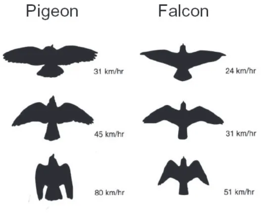
Birds and insects served as an inspiration to the aviation’s pioneers that mim-icked the wing shapes and their flapping movement, hoping it would produce
enough lift to get them of the ground. One of the most remarkable characteris-tics of birds is their ability to adapt their wing geometry in order to maximize lift according to the different flight conditions and to use the wings to produce both lift and propulsion. Figure 1-1 depicts how birds adjust the their wing geometry for different flight regimes and speeds.
Figure 1-1: Depiction of how birds adapt their wing geometry for different flight regimes.
Technology abandoned the flapping wings concept immediately after realizing the potential of fixed wings. Nowadays, aircrafts have fixed wings that produce lift and engines that produce propulsion separately.
The idea of a configurable structure, one that can change its shape and geom-etry to better respond to a particular load case, has always been on the engineers’ minds. The same way a bird can sweep its wings back and forward and configure them for high lift or low drag, engineers always wished to be able to design a wing that can be reconfigured depending on the flight regime. Airplanes today
are a design compromise. They have a fixed-wing structure that is not ideal for any part of a typical flight. Some military aircraft, like the 1970’s Grumman’s F14-Tomcat, have sweeping wings that provide some extent of morphing and adaptability.
Figure 1-2: The F14- Tomcat
Ideally, aircraft designers would like to be able to optimize their designs for every flight regimes depicted in Figure 1-3.
1. Takeoff 2.Climb
3.Cruise and weather avoidance
4.Descent
5.Landing Exterior noise, high lift
Efficiency, ride comfort, interior noise
Efficiency, damage tolerance, airframe state, control affectors
Efficiency, failure recovery
Controls, high lift, failure recovery
Figure 1-3: Flight profile, adapted from [1]
This requires a quantum leap in the areas of material science, actuation and sensing technologies as well as control engineering. The main objective of the
work presented herein is to provide a better understanding of possible shape changing, active structures. Piezoelectric actuators based on piezoelectric fibres are used to produce structural snap-through of asymmetrical carbon fibre rein-forced plastic (CFRP) laminates. Depending on the lay-up, composite laminates can, after cure, exhibit two structural and energetically stable shapes. Structures like these are called bi-stable structures. Transition from one stable shape to another can be achieved by applying an external load. When this load reaches a critical level, determined by the residual stress field and its geometry, the struc-ture will snap-through to the other stable shape through a buckling mechanism. Piezoelectric patches bonded to the surface of asymmetrical laminated carbon fibre reinforced plastics plates are used to trigger the snap-through event. In the remainder of this chapter a bibliographical survey will be made on the topics of morphing structures and state of the art actuation technologies. Next, a spe-cial section on multistable composite structures followed by another one on the Macro-Fibre Composite (MFC) actuator will give some theoretical background on the working principles of the two components of the morphing concept un-der study. Chapter two will report on the procedures and results of a first set of experiments. These initial experiments revealed some unexpected difficulties that were the motivation for the work reported in chapter three. Chapter three describes in detail the Finite Element (FE) Models developed to design a work-ing morphwork-ing plate. Special care was given to the simulation of the snap-through phenomenon, long term behaviour of asymmetrical laminates and the effect of the MFC actuator in the laminate. Based on the results from the FE models, a new set of experiments is described in chapter four, followed by a set of conclusions and recommendations for further work.
1.2
Bibliographical survey
The initial objectives of this project were to study the possibility of using em-bedded technologies to trigger snap-through of asymmetrical laminates. These
were then to be adapted to a morphing structure concept. The bibliographical survey was dispersed into different fields: morphing structures in general, asym-metrical laminates, snap-through of asymasym-metrical laminates and recent actuator technologies (embedded piezo-fibres, SMA, MFC’s, etc).
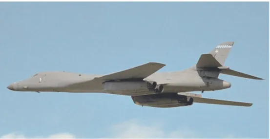
The expression ”Morphing Structures” is very undefined. In this text a mor-phing structure will be defined as one capable of macroscopic geometric changes in order to better adapt to environmental circumstances. Because of the resources available in aerospace industry and due to the clear advantages that these tech-nologies can bring, morphing structures applications are currently under study for airplanes wing geometry changes, replacement of mechanically driven control surfaces, helicopter blade control, reliable actuators for space mission, etc. If a morphing aircraft is defined merely as an aircraft that changes its configuration in-flight, it can be seen that morphing aircraft is not a new concept. Extending flaps, elevators, ailerons and wing twisting can be considered geometric changes and can be technically termed as morphing. However these changes are either necessary enablers for a controlled flight or contributors to the improved aero-dynamic performances of an aircraft. As a result, these technologies do not necessarily allow an aircraft to perform different types of mission tasks. Histor-ically the first efforts into morphing aircrafts was to design a wing that would allow the aircraft to fly in at least two speed regimes. The first design appeared in the 1920’s and was based on a wing with variable incidence. The variable sweep wing design was introduced in 1944 by German Messerschmidt and is still the most popular morphing design. It encountered many technical challenges but most were corrected and several high performance sweep wing airplanes such as Mig-23 (USSR, 1967), Grumman F-14 Tomcat (1970), and Rockwell B-1B Lancer (1983), Figure 1-4 still fly today.
Figure 1-4: Rockwell B-1B Lancer with variable sweep wings
Morphing concepts based on small wing planform changes work mainly as a replacement or enhancement of control surfaces. Rotating wingtips were used in North American’s Valkyre XB-70 (1964) to replace ailerons and elevators.
The pivoted wingtips acted both as elevators and ailerons to control the pitch (rotated together) and roll (rotated opposite). Camber control of wings using control surfaces has been extensively utilized in the aircraft industry. Most of these designs use discrete and rotating leading and trailing edge controls. Out of the two, the leading edge control surfaces are much less popular. The F-16 Fighting Falcon, developed by General Dynamics and first flown in 1974, uses leading edge flaps to change the camber of its wings. The wing has also a set of “flaperons” that combines the roles of flaps and ailerons. Recently, NASA’s Active Aeroelastic Wing (AAW) programme tested the idea of using wing twist for primary maneuvering roll control at transonic and supersonic speeds. NASA-Ames Mission Adaptive Wing Research program focus was to produce a smooth camber change avoiding the discontinuous curvature. The wing developed during this programme had an internal mechanism to flex the outer wing skin and produce a high camber section for subsonic speeds, a supercritical section for transonic speeds, and symmetrical section for supersonic speeds. Due to
Figure 1-5: Valkyre XB-70 with rotating wingtips
smoothness of the resulting wing surface, the drag was found to decrease by around 7 percent at the wing design cruise point to over 20 percent at an off-design condition, [2].
Several research groups have proposed solutions for achieving macroscopic wing morphing by using compliant mechanisms, [6]-[7]. A compliant mechanism is a single piece flexible structure that delivers the desired motion by undergoing elastic deformation as opposed by a rigid body motion in conventional mecha-nisms. It is designed to accomplish with one piece what conventional mechanisms can do with multiple pieces. It must be designed to be flexible enough to transmit motions, yet stiff enough to withstand the external loads, [6]. These mechanisms can have dramatic applications in aircraft systems as is demonstrated by Flexsys, Inc in their website (http://www.flxsys.com/).
Using innovative piezoelectric actuators, Straub et. al. [8], [9], have demon-strated a morphing concept for individual blade control of rotorcraft blades. Because of the combination of forward movement with rotation that helicopter blades have, the lift produced by each blade varies during one cycle. To solve this problem and to keep the aircraft balanced helicopter blades have trailing edge flaps that are extended and retracted in each cycle and their pitch angle
is changed accordingly. This is accomplished by a very complex mechanism at the root of the blade. Replacing this mechanism by a piezoelectric based de-vice would increase reliability an significantly reduce weight. A classification of current aircraft morphing technologies is shown in Figure 1-6.
Figure 1-6: Classification of morphing aircraft technology, adapted from [2]
Jha and Kudva, [2] identified the several technical challenges that face a mor-phing aircraft design. From the structures’ perspective, new and efficient ways of changing structural shape and size are demanded. A compliant skin in a slid-ing wslid-ing, for example, needs to be flexible to accommodate the change in the internal structures. This in turn makes it a non-load-carrying part and degrades the overall structural stiffness. For the flexible skin design, high strain materials with good structural properties and requiring less actuation force needs to be developed. In parallel, the configuration change of aircraft in-flight will require the actuators to work against aerodynamic and friction forces. It is imperative to find new ways of actuation by using aerodynamic forces, for example, for supple-mental actuation, so as to minimize the space, weight, and power requirements.
Recently, Schutlz [10] proposed a novel morphing concept based on asym-metrical CFRP laminates. If a composite laminate does not have a symasym-metrical stacking sequence, thermally induced stresses that develop during the curing process will cause an out of plane curvature. This curvature can be tailored by adjusting the stacking sequence and pre-preg thickness. Depending on the plate’s geometry these thermally induced stresses may cause the laminate to have more than one stable configuration or shape. Morphing can be obtained by a snap-through mechanism triggered by an external force. The main advantage of using these structures is that they will hold one of the stable shapes without the need of a constant applied load. Hence they can carry loads in both states as long the crit-ical snap-through load is not reached. Schultz [11]- [10] used piezoelectric patches bonded to the surface of the laminate to induce snap-through with a shear force. He successfully produced a morphing laminate based on MFC actuators and was able to make good predictions of the snap-through loads for a patch bonded in the middle of the plate. Dano [12] used SMA wires that, when heated, applied a bending moment to the plate. Hufenbach et. al [13], [14] developed optimiza-tion algorithms to dimension such laminates as well as produced a SMA based morphing, bi-stable laminates. Both Schultz and Dano were concerned with a semi-analytical approach to predict the two stable shapes of such laminates as well as the required snap-through loads. There is a significant amount of work done in the prediction of room temperature shapes of asymmetrical laminates, [15],[16]. Most of this work is based on semi-analytical Rayleigh-Ritz methods although non linear FE analysis has also been successfully used, [17], [18].
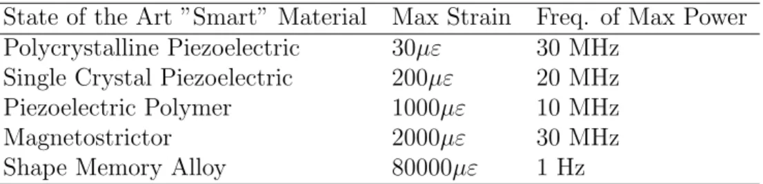
To effectively produce a morphing structure, a way must be found to acti-vate the shape changes in the bi-stable laminate. Ideally, the actuator would be powerful enough to provide the necessary loads but small and light enough to minimize its effect on the assembly. Embedding the actuator into the structure would protect it from accidental damage and is preferred to surface mounted actuation technologies. The speed at which the actuators respond can also be critical depending on the application. The following table presents a comparison
of the actuation strain that current state of the art smart materials can deliver, together with the maximum frequency at which they can operate.
State of the Art ”Smart” Material Max Strain Freq. of Max Power Polycrystalline Piezoelectric 30µε 30 MHz
Single Crystal Piezoelectric 200µε 20 MHz
Piezoelectric Polymer 1000µε 10 MHz
Magnetostrictor 2000µε 30 MHz
Shape Memory Alloy 80000µε 1 Hz
Table 1.1: Comparison of typical performance of smart materials
Piezoelectric materials are typically used for vibration suppression where high bandwidth response is desirable. On the contrary, shape memory alloys deliver significantly more force but at a quasi-static rate. Recently there has been a significant amount of effort made to increase the strain output of piezoelectric materials and embed them into a substrate. Most of these new devices are based on fibrous piezoelectric materials. Just as advanced composites offer many ben-efits over traditional engineering materials for structural design, actuators that utilize the active properties of piezoelectric fibres can improve upon many limita-tions encountered in monolithic piezoceramic devices used to control structural dynamics. The idea of a composite material consisting of an active piezoceramic fibrous phase embedded in a polymeric matrix phase remedies many of the re-strictions imposed by monolithic wafers (brittleness, large add-on mass, limited ability to conform to curved surfaces). Typically, crystalline materials have much higher strengths in the fiber form, where the decrease in volume fraction of flaws leads to an increase in specific strength. Also, in addition to protecting the fibers, the flexible nature of the polymer matrix allows the material to more eas-ily conform to the curved surfaces found in more realistic industrial applications. Presently, there is an ever-increasing number of research grade and commercially available composites containing piezoelectric fibers. However, there exist four industry leading types of promising actuators for intelligent structure:
1. The 1-3 Composites has round or square piezoelectric fibres embedded in a polymer matrix and aligned through the thickness of the device. These
devices are typically used for ultrasound and acoustic control applications
2. The Active Fibre Composite was developed by the Active Materials and Structures Lab at MIT and are another type of piezoceramic fibre compos-ite. The device uses uniaxially aligned piezoceramic fibres surrounded by a polymer matrix and can include inactive glass fibres for increased structural strength.
Figure 1-7: Schematics of the Active Fibre Composite actuator
3. Finally, the Macro Fibre Composite actuator was developed at NASA Lan-gley Research Center. The design principle is the same as the AFC’s but the piezoelectric fibers used have a rectangular cross-section. This way, a larger area of piezoelectric material is in contact with the electrodes thus in-creasing the overall performance. Rectangular fibres can be easily obtained by cutting from traditional ceramic wafers.
One last class of fibre based piezoelectric actuators still under research are those consisting of hollow piezoelectric fibres. The major drawback to the AFC ap-proach described above is the requirement of the electric field to pass through the polymeric resin serving as matrix to the fibres. Due to the placement of the electrode on the matrix surface, electric field losses are significant, requiring high voltages for actuation. Furthermore, this approach limits the matrix to
electri-Figure 1-8: The MFC patch actuator
cally nonconductive materials which is particularly a problem in large structure and air vehicle applications where metals and carbon fibers are almost exclusively utilized in construction. Hollow fibers, individually electroded on both the in-side and outin-side surfaces are activated by an electric field applied directly across the fibre, generating longitudinal strain due to the piezoelectric d31 mode. The
piezoelectric modes are defined in Section 1.4.1
Figure 1-9: Schematics of a hollow piezoelectric fibre [3]
Even though the longitudinal strain is decreased by half by using the d31
mode instead of the d33 mode in conventional AFC’s, it is possible to reduce
only through the fibre’s thickness. The electric field losses in the matrix are also reduced. Another benefit of the hollow fibre topology is that the inner electrode is isolated from the matrix enabling the fibre to be embedded in electrically conductive matrices. Published studies [3] suggest that design parameters such as fibre aspect ratio, volume fraction and matrix/fibre modulus ratio play a role in the performance characteristics. Hollow piezoelectric active fibre composites are not yet commercially available, as is the case of the MFC actuators. They are, however, considered likely candidates to provide actuation for small morphing structures.
1.3
Multistable laminates
In order to understand why certain laminates assume two stable geometries it is necessary to briefly review the fundamentals of classical lamination theory.
1.3.1
Classical lamination theory at a glance
Knowledge of the variation of stress and strain through the laminate thickness is essential for the definition of the extensional and bending stiffness of a laminate. The following assumptions are considered
1. The laminate is assumed to be a series of perfectly bonded plies. Moreover, the bonds are presumed to be infinesimally small as well as non-shear-deformable. That is, the displacements are continuous across ply bound-aries so that no relative slippage can occur relative to another.
2. The laminate is assumed to be ”thin”. That is to say, that a line origi-nally straight and perpendicular to the middle surface is assumed to re-main straight and perpendicular to the middle surface after deformation. The consequence of this is that the shearing strains in planes perpendicular to the middle surface are ignored, i.e. γxz = γyz = 0.
3. Finally, the normals are presumed to have constant length so that the strain perpendicular to the middle surface is ignored as well, i.e. εzz = 0
The displacement field resulting from these assumptions is given by:
u = u0− z ∂w0 ∂x (1.1) v = v0− z ∂w0 ∂y
The laminate strains have been reduced to εx, εy and γxy by virtue of the
Kirchhoff hypothesis. For small strains (linear elasticity), these are defined in terms of of displacements as:
εx = ∂u ∂x (1.2) εy = ∂v ∂y γxy = ∂u ∂y + ∂v ∂x
Thus, introducing the derived displacements from equations (1.1) into equa-tion (1.2): εx = ∂u0 ∂x − z ∂2w 0 ∂x2 (1.3) εy = ∂v0 ∂y − z ∂2w 0 ∂y2 γxy = ∂u0 ∂y + ∂v0 ∂x − 2z ∂2w 0 ∂x∂y or: εx εy γxy = ε0 x ε0 y γ0 xy + z κx κy κxy (1.4) where:
ε0 x ε0 y γ0 xy = ∂u0 ∂x ∂v0 ∂y ∂u0 ∂y +∂v∂x0 (1.5) and: κx κy κxy = − ∂2w0 ∂x2 ∂2w 0 ∂y2 2∂2w0 ∂x∂y (1.6)
By substitution of the strain variation through the thickness (equation 1.3) in a stress-strain relation, the stresses in the kth layer can be expressed in terms
of the laminate middle-surface strains and curvatures as
σx σy τxy = ¯ Q11 Q¯12 Q¯16 ¯ Q12 Q¯22 Q¯26 ¯ Q16 Q¯26 Q¯66 ε0 x ε0 y γ0 xy + z κx κy κxy (1.7)
The terms ¯Qij are the transformed reduced stiffnesses, i.e. stiffness given in
the global coordinate system. The terms ¯Qij are related to the reduced stiffnesses
in the local coordinate system by equations 1.8.
¯
Q11 = Q11cos4θ + 2(Q12+ 2Q66) sin2θ cos2θ + Q22sin4θ (1.8)
¯
Q12 = (Q11+ Q22− 4Q66) sin2θ cos2θ + Q12(sin4θ + cos4θ)
¯
Q22 = Q11sin4θ + 2(Q12+ Q66) sin2θ cos2θ + Q22cos4θ
¯
Q16 = (Q11− Q12− 2Q66) sin θ cos3θ + (Q12− Q22+ 2Q66) sin3θ cos θ
¯
Q26 = (Q11− Q12− 2Q66) sin3θ cos θ + (Q12− Q22+ 2Q66) sin θ cos3θ
¯
Q66 = (Q11+ Q22− 2Q12− 2Q66) sin2θ cos2θ + Q66(sin4θ + cos4θ)
The terms Qij are the reduced stiffness in the ply coordinate system and are
Q11 = E1 1 − ν12ν21 (1.9) Q12 = ν12E2 1 − ν12ν21 = ν21E1 1 − ν12ν21 Q22 = E2 1 − ν12ν21 Q66 = G12
The resultant membrane forces and bending moments acting on a laminate are obtained by integration of the stresses in each layer or ply through the laminate thickness Nx Ny Nxy = Z t/2 −t/2 σx σy τxy dz = N X k=1 Z zk zk−1 σx σy τxy k dz (1.10) and Mx My Mxy = Z t/2 −t/2 σx σy τxy zdz = N X k=1 Z zk zk−1 σx σy τxy k zdz (1.11)
Substitution of equation 1.7 into equations 1.10 and 1.11 yields
Nx Ny Nxy = N X k=1 ¯ Q11 Q¯12 Q¯16 ¯ Q12 Q¯22 Q¯26 ¯ Q16 Q¯26 Q¯66 k Z zk zk−1 ε0 x ε0 y γ0 xy k dz + Z zk zk−1 κx κy κxy k zdz (1.12)
and Mx My Mxy = N X k=1 ¯ Q11 Q¯12 Q¯16 ¯ Q12 Q¯22 Q¯26 ¯ Q16 Q¯26 Q¯66 k Z zk zk−1 ε0 x ε0 y γ0 xy k zdz + Z zk zk−1 κx κy κxy k z2dz (1.13) These equations can be rearranged in terms of the midplane strains and cur-vatures as Nx Ny Nxy = A11 A12 A16 A12 A22 A26 A16 A26 A66 ε0 x ε0 y γ0 xy + B11 B12 B16 B12 B22 B26 B16 B26 B66 κx κy κxy (1.14) and Mx My Mxy = B11 B12 B16 B12 B22 B26 B16 B26 B66 ε0 x ε0 y γ0 xy + D11 D12 D16 D12 D22 D26 D16 D26 D66 κx κy κxy (1.15) where Aij = N X k=1 ( ¯Qij)(zk− zk−1) (1.16) Bij = 1 2 N X k=1 ( ¯Qij)(zk2− zk−12 ) (1.17) Dij = 1 3 N X k=1 ( ¯Qij)(zk3− zk−13 ) (1.18)
In equations 1.18 the Aij are the extensional stiffness, the Bij are the
bending-extension or membrane coupling stiffness and the Dij are bending stiffness. When
a laminate stacking sequence is symmetrical about the midplane, the Bij
only and no curvature, the same way that bending moments will cause curvature and no in-plane strains. In unsymmetrical laminates however the coupling terms are nonzero and thus, membrane forces will cause out of plane curvatures. The different effects of the coupling terms can be seen in Figure 1-10.
Figure 1-10: Laminate coupling relationships
1.3.2
Laminate thermal stresses
The equations of lamination theory for thermal stress analysis can be derived following essentially the same procedure as used for mechanical loading, but with the use of thermo-elastic lamina constitutive equations. It is assumed that the total strains are the superposition of mechanical strains.
{ε} = {ε0} + z{κ} + {εt} = {εσ} + {εt} (1.19) The final form of the thermo-elastic laminate analysis is:
N + Nt M + Mt = A B B D ε0 κ (1.20)
The equivalent thermal force per unit length and thermal moment per unit length are given respectively by:
{Nt} =
Z H
−H
{Mt} =
Z H
−H
[ ¯Q]k{εt}kzdz (1.22)
When a temperature change 4T is applied to the laminate, in-plane strains appear and are a function of the materials coefficients of thermal expansion (CTE).
ε = α4T (1.23)
From the expressions above, it would be safe to assume that, given that the Kirchhoff hypothesis are valid and that the material engineering constants and CTE are know, a closed form solution for the curvature development of laminates during the curing cycle could be obtained. In fact, some commercially available design softwares use CLT to predict laminate stresses due to temperature changes do processing. According to the results provided also by linear FEA, square asymmetrical [0◦/90◦] laminates have only one stable configuration with equal
curvature in both its principal axes. This defines a saddle. Experiments and geometrically non-linear FEA show that this is not true. In fact, the laminates assume a cylindrical shape with large curvature in one principal direction and a negligible curvature in the perpendicular direction. Additionally, the laminate is bi-stable, meaning that it can be snapped to another configuration where the axis of the cylinder shape rotates by 90◦, Figure 1-11.
Figure 1-11: Shapes obtained with CLT and with non-linear FEA.
Clearly, the curvature development is a geometrically non-linear phenomenon. The combination of asymmetrical stacking sequences is limitless. Varying the ge-ometric parameters and number of plies, interesting shapes and functional struc-tures can be created, outperforming the traditional ”black aluminum” concept. Figure 1-12 shows the two stable shapes of a long [0◦/90◦] rectangular slab.
Figure 1-12: Example of extreme shape change accomplished with an asymmet-rical laminate.
There is a pending issue that needs to be resolved before these structures take their places in the designers’ drawing boards. There is no closed form method to develop a multi-stable, asymmetrical laminate based on derived requirements except for those particular cases which have already been extensively studied (square plates with simple cross ply stacking sequences). It is foreseeable that multi-stable laminates will be part of a structural system built of traditional
materials. Integrating these laminates into traditional, symmetrical ones or even into metallic structures has not yet been tried or tested.
1.4
Macro-Fibre composite actuators
1.4.1
Piezoelectric effect and materials
The piezoelectric effect was discovered by Pierre and Jacques Curie when they were 21 and 24 years old in 1880. The word piezo is Greek for ”push”. The piezo-electric effect is demonstrated by crystals that become piezo-electrically polarized when subjected to a mechanical strain. Owing to its asymmetric crystalline structure, piezoelectric materials generate an electric field across the materials when a me-chanical strain in applied to them (direct piezoelectric effect). This relationship is reversible, so the application of an electric field to a piezoelectric material will induce a mechanical strain (converse piezoelectric effect). Some natural materials such as quartz and tourmaline display piezoelectric properties, but the effects are relatively small. Improvements in piezoelectric performance have been achieved with the development of polycrystalline ferroelectric materials such as Barium Titanate (BaTiO3) and Lead Zirconate Titanate (Pb(Zr,Ti)O3). PZT is the
most widely used material in actuator applications. It is available in a variety of forms to account for different performance demands. Crystals in raw PZT fibres are randomly orientated, as they have not been exposed to an electric field. In this state they are ferroelectric isotropic materials, displaying poor piezoelectric performance. To demonstrate useful piezoelectric properties, the PZT must be permanently polarized, providing an anisotropic material. Remnant polarisation is achieved by applying a sufficiently large electric field to the material, aligning crystals in the required direction. A ferroelectric crystal that is spontaneously polarized will try to minimize its electrostatic energy by forming Weiss domains. Weiss domains are regions in which aligned cells are parallel to one another. The application of a suitable electric field will generate a homogenous region in the PZT material, orientated in the desired direction. To achieve remnant
polariza-tion, an electric field of sufficient strength must be applied for a prolonged time period and at an elevated temperature. Ideal poling conditions for the Type 5H2 PZT material are an electric field strength of 2kV/mm, for a time of 20 min-utes at a temperature between 50-60◦C. When the electric field is removed there
is some relaxation and crystals deviate from their position, Figure 1-13. This reorientation of crystals is small and the anisotropic material properties remain [19].
Figure 1-13: Polarization of piezoelectric crystals.
Once the PZT is polarized, only a small fraction of the polarizing field is needed to activate it. An electric field applied in the polarization direction will result in a longitudinal strain x3 and a transverse strain x1 = x2, Figure 1-14.
Figure 1-14: Piezoelectric strains.
The relations between the applied field and the strains are given by equations ( 1.24) and ( 1.25).
x3 = d33E3 (1.24)
x1 = d31E3 (1.25)
The first equation is known as the d33 mode of activation while the second
governs the d31mode. The longitudinal piezoelectric constant is two times larger
than the transverse constant. A number of actuators combine the piezoceramic with a displacement amplification mechanism to tackle the inherent limited stroke of the piezoceramics. Architectures such as stacks, bender actuators, unimorph actuators and building block actuators are only a few examples of how this limita-tion can be surpassed. The simplest form of amplificalimita-tion, the stacks, consists of thin piezoceramic patches stacked to linearly increase their overall deflection while maintaining a low voltage requirement. The bender actuator architecture uses the internal piezoelectric strain to indirectly induce actuator motion. Benders consist of two or more layers of piezoelectric material that are poled and acti-vated such that layers on opposite sides of the neutral axis have opposing strains. A special case of the bender actuator architecture is a unimorph. A unimorph is a composite beam, plate, or disk with one active layer and one inactive layer, or substrate. RAINBOW, ceramic biased oxide wafer (CERAMBOW), Crescent, and THUNDER actuators are typically referred to as unimorph benders [20].
1.4.2
Macro Fibre Composite
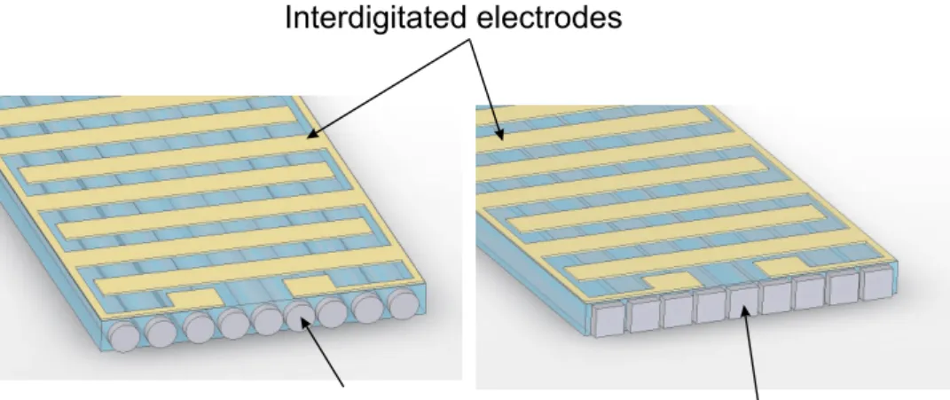
The Macro Fibre Composite (MFC) actuator is part of an emerging technology that strives to improve the current state of the art for structural actuation, which currently relies heavily upon monolithic piezoceramic materials. The MFC is a layered, planar actuation device that employs rectangular cross section, unidi-rectional piezoceramic fibers embedded in a thermosetting polymer matrix. This active, fiber-reinforced layer is then sandwiched between copper-clad Kapton film layers that have an etched interdigitated electrode pattern. During
manufactur-ing, these layers are laid-up by hand and then cured in a vacuum hot-press. After the epoxy matrix that bonds the package together is fully cured, a high DC voltage (1500 V) is applied to the electrodes, thereby poling the piezoceramic material in the plane of the actuator and establishing the poling direction parallel to the PZT fibers. This in-plane poling and subsequent in-plane voltage actua-tion allows the MFC to utilize the d33piezoelectric effect, which is much stronger
than the d31 effect used by traditional PZT actuators with through-the-thickness
poling.
Figure 1-15: Layers of an MFC actuator [4]
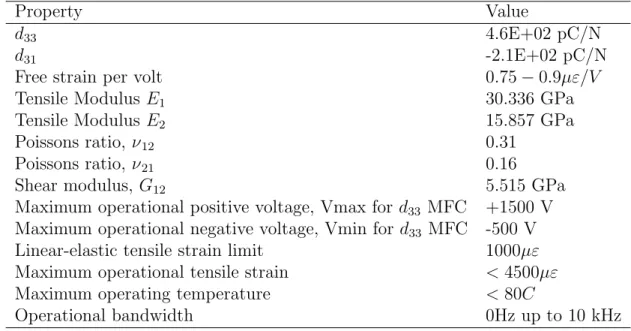
A summary of the most important MFC engineering properties are listed in Table 1.2.
Property Value
d33 4.6E+02 pC/N
d31 -2.1E+02 pC/N
Free strain per volt 0.75 − 0.9µε/V
Tensile Modulus E1 30.336 GPa
Tensile Modulus E2 15.857 GPa
Poissons ratio, ν12 0.31
Poissons ratio, ν21 0.16
Shear modulus, G12 5.515 GPa
Maximum operational positive voltage, Vmax for d33 MFC +1500 V
Maximum operational negative voltage, Vmin for d33 MFC -500 V
Linear-elastic tensile strain limit 1000µε Maximum operational tensile strain < 4500µε
Maximum operating temperature < 80C
Operational bandwidth 0Hz up to 10 kHz
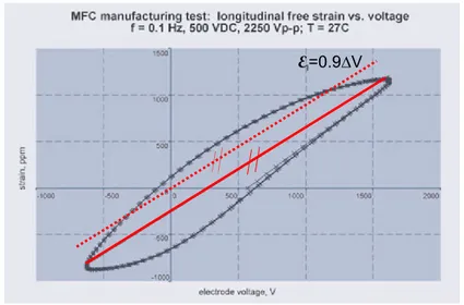
The performance indicator of this actuator is its free strain per applied voltage value. The voltage versus strain characteristics is nonlinear and shows hysteresis, Figure 1-16.
Figure 1-16: MFC voltage versus strain characteristics.
The free-strain per volt value is an approximate linear proportionality factor obtained from the line shown in solid red. In this work, the MFC actuation will be recreated by an equivalent thermal expansion coefficient. Thermal expansion is considered a linear effect represented by a single value and it is difficult to represent the nonlinear behaviour as well as the hysteresis. In fact, the true simulated behaviour is the one shown in dashed red line in Figure 1-16.
Initial Exploratory Investigation
Supported by published results, a first set of experiments was prepared early in the project. The objective of these first experiments was to use available rect-angular MFC patches measuring 85 mm by 28 mm in square [0◦/90◦] laminates.
The pre-preg used was the AS4/8552 carbon fibre/epoxy combination and the standard procedure to manufacture the plates was used (Figure 2-1).
Five curved, bi-stable, 150 mm by 150 mm plates were manufactured. The next step was the bonding of the MFC on the plate’s surface. The direction and alignment of the MFC’s is critical and it should be bonded in a way that when activated the actuator ”flattens” the plate, Figure 2-2.
Figure 2-2: Direction in which the MFC should be bonded.
The bonding surface needs to be prepared with sandpaper first. The surface is considered ready to receive the adhesive when water wets it and sticks to it, instead of forming bubbles (wet-out test).
Figure 2-3: Preparing the laminate’s surface.
Both the MFC and the laminate are cleaned with acetone and kept in closed bags to avoid contamination.
Figure 2-4: The bi-stable laminate, the MFC patches and the adhesive before bonding.
Araldite Rapid epoxy adhesive was chosen for the preliminary tests because it was readily available. This adhesive cures at room temperature and has a high viscosity. A layer of adhesive was applied to the laminate’s bonding surface with a spatula and the patch was placed and kept in place with the help of tape. A vacuum bag was used to ensure that a uniform pressure was applied as well as any air bubbles trapped in the epoxy layer would disappear during the cure.
Figure 2-5: Vacuum bag used to cure the adhesive.
Figure 2-6 shows the MFC patch bonded to the laminate after the adhesive cured. The overflow of epoxy can be clearly seen and results in a odd looking bond. The bondline thickness also looks to thick.
Figure 2-6: MFC patch bonded to the CFRP laminate.
Immediately after the cure a problem was detected. Although it was still possible to manually snap the plate to the other state, it required much more effort. Additionally, the plate did no remain in the alternative state for long but rather snapped back to its original configuration. Figure 2-7 illustrates this: as an external force is applied (green) there is an opposing spring-like force (red) that develops and prevents the laminate from snapping through. The magnitude of this spring-like force is significant. The laminate also became much thicker and stiffer when compared to laminates produced at the same time but without patches.
Figure 2-7: Spring effect.
Nevertheless the patch was tested and was actuated by a 1500 V DC power supply. As expected, little or no movement was seen. In another attempt, two MFC patches were bonded using the exact same procedure described above. The idea was to double the actuation force keeping the same underlying bi-stable
structure, Figure 2-8.
Figure 2-8: Two MFCs bonded to the laminate.
Again, the results were very clear once the adhesive layer was cured. The stiffness of the laminate increased even more and it was even more difficult to snap. By the end of these first experimental investigations several questions were unanswered:
1. What is the appropriate actuator size?
2. What is its effect on the laminate’s stiffness?
3. How powerful does the actuator need to be?
4. Can the MFC be used to trigger snap-through in both ways?
To answer these questions a reliable FE analysis model had to be developed. This is the topic of the next chapter.
Finite Element Simulations
3.1
Introduction and scope
After the initial experiments that lead to unexpected results, it was decided to develop a simulation based on finite element (FE) analysis. Finite element mod-elling was used for several purposes. First, to reproduce the cured shapes of the asymmetrical laminates. This is not a new approach for this problem as FE predictions of asymmetrical laminates’ shapes are documented for example in reference [15]. The cure of [0◦/90◦], [0◦/45◦], [45◦/ − 45◦] square laminate
were simulated and their shapes and snap-through behavior was compared to experimental data. This first task was useful to gain insight on the snap-through phenomenon. It was also necessary to confirm the analysis procedures and sim-plifying assumptions typical of FE analysis (i.e. boundary conditions, applied loads and the material properties). The second purpose of the FE analysis was to simulate the combined laminate/actuator system. The model should be help-ful in predicting the changes in the laminate’s stiffness due to the presence of the actuator. Having accomplished this, the model should also help predict the volt-age required to induce the snap-through effect of the laminates. Again, a square [0◦/90◦] laminate with a MFC actuator bonded to it was modelled. This
config-uration was chosen because of available experimental data not only in literature, [10], but also in the tests performed during this project. Finally, a large number
of models were created in order to chose the best laminate/MFC configuration. The parameters for this design process were:
1. Stacking sequence;
2. Laminate size;
3. Laminate thickness;
4. Actuator size;
5. Actuator orientation.
In the following sections these analysis and methods will be described in detail and the results will be presented and discussed.
3.2
Modelling the curvature development
3.2.1
Theory
The first task in the modelling effort was to accurately predict the cured shapes and snap-through phenomenon of the asymmetrical laminates. For that purpose, a square laminate plate with side length of 150mm was modelled. The plates’s geometry and boundary conditions are depicted in Figure 3-1. The central node was clamped. Although the plates’ nominal length was 150mm, is was necessary to include some geometric imperfections into the FE model. The sketch is not a perfect square but rather a rectangle with side lengths of 149 mm by 151 mm. This is considered to be acceptable as the manufactured plates will also include imperfections in its dimensions and due to fibre misalignments. Using perfectly square plates in the FE model will make the analysis converge to unstable saddle shapes instead of stable cylindrical ones. The reason why this happens is still not clear. However, a hypothesis was formulated that this is related with the fact that the FEM developed does not handle the inertia forces. A good argument in favour of this hypothesis is the fact that this only happens in an implicit static
Figure 3-1: FE model boundary conditions
analysis (i.e. using Abaqus/Standard, for example). If instead of an implicit method an explicit method or a implicit direct-integration dynamic method is used to predict the cured shapes, the perfectly square plate will converge into a cylinder. In an explicit or direct-integration dynamic method, Abaqus solves the dynamic equilibrium equation in which the inertia effects are considered. An Abaqus/Explicit model was created that verified this. The main disadvantage of explicit models is the associated computational cost. Although the effort asso-ciated to a time step is very small, it is usually necessary to have thousands of time steps before an analysis is complete. In this particular case this increases the total run time from a couple of minutes to several hours or even days using a PC. The implicit direct-integration dynamic method solves the dynamic equi-librium equations for dynamic quantities at time t + ∆t based not only on values at t, but also on these same quantities at t + ∆t. But because they are implicit, nonlinear equations must still be solved [21]. The total run time is shorter than in explicit models but still too long to be useful for design purposes. Thus, an explanation for the problem was, in principle, found. Although a way was found to make perfectly square plates converge into a cylinder instead of into a saddle, the traditional method of including a geometric imperfection was adopted any-way. The reason for this is the time it takes to run an explicit analysis compared to an implicit one and the accurate results that the implicit method provides regardless of the geometric imperfections introduced. In every model, nonlinear
geometry was considered.
3.2.2
Model description
Two materials were used for the initial tests and, consequently for the analysis: the AS4-8552 and T800-977-2 carbon fibre prepreg. The mechanical properties of these two prepregs used in the models are listed in table 3.1 SI units were used in all the models.
Property Value (AS4-8552) Value (T800-2020)
E1 135 GPa 294 GPa E2 9.5 GPa 9.5 GPa ν12 0.3 0.3 G12 5 GPa 5 GPa G13 7.17 GPa 7.17 GPa G23 3.97 GPa 3.97 GPa α1 −2 × 10⁻⁸/◦C −2 × 10⁻⁸/◦C α2 −3 × 10⁻⁵/◦C −2.25 × 10⁻⁵/◦C tply 0.255 mm 0.180 mm
Table 3.1: Mechanical properties of the AS4-8552 and the T800-977-2 pre-pregs used in the FE models
Although the T800 fibre is much stiffer then the AS4 one, the pre-preg ply thickness is roughly 60% of the AS4 one. Since the snap-through phe-nomenon is achieved by applying a bending moment, it is the flexural stiff-ness that plays a central role. The bending stiffstiff-ness matrix is computed as: [D] = 1 3 2 X k=1 £¯ Q¤k¡z3 k− zk−13 ¢
The cubic dependence of the ply thickness is noto-rious. Hence, a 60% change in ply thickness will have a significant effect in the laminate’s bending stiffness. Thus, the T800 material was used in the second set of experiments and in the following FE models unless otherwise specified in the text.
General purpose composite shell elements were used (type S4R). The meshes have approximately 900 elements. The analysis was divided into two different steps as shown in Figure 3-2. An initial temperature field of 180◦C was imposed
max-imum temperature which is taken as the stress-free temperature as well. Step one is a simple *STATIC step where large deformation theory was used (NLGEOM) to calculate the plate’s deformation due to a temperature change of ∆T = 160◦C.
Figure 3-2: Representation of the analysis steps used
Figure 3-3 represents the plate at the end of this first step together with the undeformed mesh.
Figure 3-3: FE plot of the deformed plate at the beginning of the snap-through step. Scale factor=1
This displacement field shown in Figure 3-3 is qualitatively in good agreement with that observed in real plates. The curvatures were calculated as part of the output (*OUTPUT FIELD, SE) and compared to those measured in the real plates. The procedure to measure the curvature was taken from reference [10] and consists of tracing the contour of the laminate onto a white paper.
Figure 3-4: Definition of parameters used to calculate the curvature
The geometric parameters described in Figure 3-4 were measured and the curvatures were calculated using the equations (3.1)
R = sin µ tan−1 µ d h ¶¶√ d2+ h2 sin µ π − 2 tan−1 µ d h ¶¶ (3.1) κ = 1 R
The curvature directions and the way they are defined is shown in Figure 3-5.
Figure 3-6 shows the Abaqus output plot for the surface curvatures of [0◦/90◦],
[45◦/ − 45] and [0◦/45◦] square 150 × 150 mm laminates.
Figure 3-6: FE contour plots of the three principle curvatures for the three dif-ferent lay-ups
These plots show that, as expected, the distribution of curvatures is affected by the plates’ boundaries. The middle section has a relatively constant curvature and this can be compared to measurements in real plates.Figure 3-7 pictures a qualitatively comparison between shapes obtained in the FE models and the ones observed in the manufactured laminates.
Figure 3-7: Comparison between FE shapes and those of the manufactured lam-inates.
Measured (1/m) Finite Element (1/m) Error(%)
κy 6.51 6.65 2.1
Table 3.2: Comparison between measured curvature and curvature obtained with FE
For the [45◦/ − 45◦] laminates a different set of boundary conditions had to
be used, Figure 3-8. Clamping the middle node was not enough to prevent the laminate to converge into an unstable shape regardless of the geometric imper-fection used. Again, the explicit version of this model converged effortlessly into the stable shape without the need for geometric imperfections and with only the middle node clamped.
Figure 3-8: Boundary conditions used on the [45◦/ − 45◦]
T laminate models
The curvature measurements were made after the plates were dried and dis-sicated.

![Figure 1-6: Classification of morphing aircraft technology, adapted from [2]](https://thumb-eu.123doks.com/thumbv2/123dok_br/19177656.943916/30.892.192.727.318.624/figure-classification-morphing-aircraft-technology-adapted.webp)
![Figure 1-12 shows the two stable shapes of a long [0 ◦ /90 ◦ ] rectangular slab.](https://thumb-eu.123doks.com/thumbv2/123dok_br/19177656.943916/42.892.208.709.714.832/figure-shows-stable-shapes-long-rectangular-slab.webp)