16 artigo 452
TECHNICAL NOTE
1- Orthopedic Physician, Hospital Samaritano in São Paulo, SP and Hospital Antonio Giglio in Osasco - São Paulo, SP, Brazil.
2- Doctor and Professor of the Department of Orthopedics and Traumatology of the Faculty of Medical Sciencies, UNICAMP – Campinas, SP, Brazil.
Work carried out at the Orthopedics and Traumatology Service (SOT) of the Hospital Samaritano of São Paulo (HS-SP) – Hip Group. Correspondence: Rua Capote Valente, 154, ap.61 – CEP 05409-000 – São Paulo, SP. E-mail: [email protected]
Received for publication: 11/15/2010, accepted for publication: 05/25/2011.
THE MINUS
®SySTEM MINIMALLy INVASIVE TECHNIqUE
FOR THE TREATMENT OF TRANTROCHANTERIC FRACTURES
Rogério Naim Sawaia¹, William Dias Belangero²
The authors declare that there was no conflict of interest in conducting this work
This article is available online in Portuguese and English at the websites: www.rbo.org.br and www.scielo.br/rbort
ABSTRACT
The MINUS system was developed as a minimally invasive procedure that uses a diaphyseal cephalic extra-medullary implant for the treatment of transtrochanteral fractures of the femur in elderly patients. The implant consists of a sliding screw coupled to a plate adapted to the minimally invasive technique. The surgical access is approximately three centimeters in length located on the lateral surface of the hip, below the projection of the small trochanter. A perfectly adapted instrument was used for the procedure, which also requires the use of an image
intensifier, reducing surgery time and rate of bleeding. The objective of this study is to present a new instrument and implant, developed specifically for treatment with the minimally invasive technique, reducing the length of the conventional surgical access from 10 to three centimetres. This new implant was given the commercial name of MI-NUS System.
Keywords - Surgical Procedures, Minimally Invasive; Hip Fractures; Femoral Fractures; BoneScrews
INTRODUCTION
The advent of minimally invasive techniques has provided better results from treating complex fractures produced by high-energy trauma, gener-ally associated with severe soft-tissue lesions(1). This
treatment methodology has also been shown to be advantageous for intertrochanteric fractures of the femur, thereby reducing the bleeding and pain and providing earlier rehabilitation for these patients, who are mostly elderly(1-7).
Today, the principle used is one of relative sta-bility through intra and extramedullary implants, represented by sliding pin plates and intramedullary nails(7-11). Among sliding screw systems, the biggest
representative is the implant known as the dynamic hip screw (DHS)®, which is considered to be the gold standard(4,5,9) for treatment of these fractures.
The technique uses a wide access route, with bleed-ing levels proportional to the size of the incision(12).
METHOD
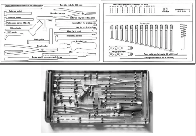
The MINUS system is composed of a sliding pin coupled to a plate with three holes and instruments that were developed specifically for introducing this implant(13). Below, the instruments and implant are
described:
Instruments
One depth measurement device for sliding pins: alu-minum B221M;
One plate guide: aluminum B221M;
Two bits (ø 3.2 x 250 mm): stainless steel AISI 420; One external jacket: stainless steel AISI 420;
One external jacket: stainless steel AISI 420;
One plate guide screw (M6 x 1): stainless steel AISI 420; One bit protector: stainless steel AISI 420;
Figure 1 – Box containing instruments and implants. Schematic drawing and photograph.
Sliding pins
Key for cortical screws Internal key for sliding pins External key for sliding pins
Male (ø 13 mm)
Impacting device
Ratchet key
Mill
Screw depth measurement device Depth measurement device for sliding pins
External jacket
Internal jacket
Plate guide screw (M6 x 1)
Bit protector 135º guide
Two bits (ø 3.2 x 250 mm)
Rotation forceps
T key
Plate guide
Rotation key
28 30 32 34Self-tapping cortical screws (ø 4.5 mm)36 38 40 42 44 4648 50 52 54
Forceps 54
50 40 30 20 0
60mm 65mm 70mm 75mm
80mm 85mm 90mm 95mm
100mm105mm
110mm115mm120mm
Minus plate (2)
Four calibrated wires (ø 2.5 x 230 mm) Four guidewires (ø 2.5 x 300 mm)
0 120 110 100 90 80 70 60
115 105 95 85 75 65 One rotation forceps: stainless steel AISI 420;
One rotation key: stainless steel AISI 420; One male (ø 13 mm): stainless steel AISI 420; One screw depth measurement device: stainless steel AISI 420;
One impacting device: stainless steel AISI 420; One external key for sliding pins: stainless steel AISI 420; One internal key for sliding pins: stainless steel AISI 420; One key for cortical screws: stainless steel AISI 420; Four calibrated guidewires (ø 2.5 x 230 mm): stain-less steel ASTM F138;
Four calibrated guidewires (ø 2.5 x 300 mm): stain-less steel ASTM F138;
Note: All the instruments are milled, except for the forceps and rotation keys, which are forged.
Implant
Self-tapping cortical screw (ø 4.5 mm), of lengths 28 mm to 54 mm, in 2-mm steps: stainless steel ASTM F138 or titanium alloy ASTM F136;
Sliding pin with hexagonal head, of lengths 60 mm
to 120 mm, in 5 mm steps): stainless steel ASTM F 138 or titanium ASTM F136;
MINUS plate with three holes: forged titanium ASTM F136 / ASTM F620; plate thickness: 6.5 mm
Note: All the implants are milled, with the excep-tion of the plate, which is forged (Figure 1).
SURGICAL TECHNIqUE:
Figure 2 – Positional of the patient on the conventional table.
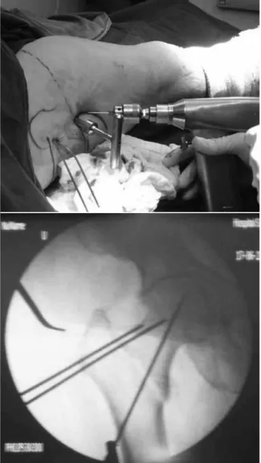
Figure 3 – Reduced fracture, provisionally fixed with two percu-taneous Kirchner wires.
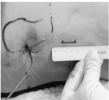
Figure 4 – Determination of starting point for the access route.
After the reduction, the fracture is provisionally fixed using two Kirschner wires, of diameter 2.0 mm, which are inserted into the lateral face of the greater trochanter and go through the upper part of the femo-ral neck towards the femofemo-ral head (Figure 3).
The incision is made 2 cm below the base of the lesser trochanter, at the intersection point with the femoral diaphysis. When this reference point is frac-tured or avulsed, the incision is started 2 cm distally to the end of the projection of the calcar, and is 3 cm in length (Figure 4).
After opening the skin, subcutaneous cellular tis-sue and fascia lata, the vastus lateralis muscle is
Figure 5 – Positioning of the guidewire using the 135º guide.
Figure 6 – Introduction of the MINUS plate.
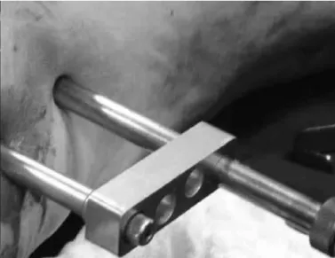
Figure 7 – Plate in position and stabilized with a distal screw using the extramedullary guide.
lata. The sliding pin chosen should be 5.0 mm longer than the measurement, so that it remains protruding on the lateral face of the lateral cortical bone of the femur, thus making it easier to fit the plate on the screw. The plate should be slid close in to the bone, below the musculature, with the tube turned towards the surgeon, using the plate forceps. As soon as it has been introduced, it is turned through 180° on its axis, so that the tube is introduced over the screw (Figure 6). Since these are elderly patients with flac-cid musculature, this part of the procedure is carried out without great difficulty. Using the external guide, the plate holes are located and drilling for the distal screw is started, in order to position the plate at the
center of the diaphysis (Figure 7). The two distal screws are introduced percutaneously by means of a 0.5 cm accessory route, and the proximal screw through the main route. After this, the final closure is performed (Figure 8).
FINAL REMARKS
Figure 8 – Final appearance of skin closure.
Figure 7B – Plate in position and stabilized with a distal screw using the extramedullary guide.
Several studies have compared the two systems and have not found significant differences in relation to length of the surgery, blood loss, consolidation and postoperative mortality(18-20).
Other types of minimally invasive implants can also be used, such as external fixators and, most re-cently, percutaneous compression plating (PCCP)(1),
which has not yet been tested on a large scale.
REFERENCES
1. Kuzyk PR, Guy P, Kreder HJ, Zdero R, McKee MD, Schemitsch EH. Mini-mally invasive hip fracture surgery: are outcomes better? J Orthop Trauma. 2009;23(6):447-53.
2. Janzing HM, Houben BJ, Brandt SE, Chhoeurn V, Lefever S, Broos P, et al. The Gotfried PerCutaneous Compression Plate versus the Dynamic Hip Screw in the treatment of pertrochanteric hip fractures: minimal invasive treatment reduces operative time and postoperative pain. J Trauma. 2002;52(2):293-8.
3. Sawaia RN, Belangero WD. Estudo comparativo entre a técnica de miniincisão e a via de acesso a foco aberto para o tratamento das fraturas transtrocante-rianas. Rev Bras Ortop. 2005;40(3):106-18.
4. Lee YS, Huang HL, Lo TY, Huang CR. Dynamic hip screw in the treatment of intertrochanteric fractures: a comparison of two fixation methods. Int Orthop. 2007;31(5):683-8.
5. Alobaid A, Harvey EJ, Elder GM, Lander P, Guy P, Reindl R. Minimally invasive dynamic hip screw: prospective randomized trial of two techniques of insertion of a standard dynamic fixation device. J Orthop Trauma. 2004;18(4):207-12.
6. Chong KW, Wong MK, Rikhraj IS, Howe TS. The use of computer navigation in performing minimally invasive surgery for intertrochanteric hip fractures—The experience in Singapore. Injury. 2006;37(8):755-62.
7. Baumgaertel, F. Placas em ponte. “Princípios AO do tratamento de fratura”. In.: Ruedi TP, Murphy W M. Porto Alegre: ArtMed; 2002. p. 221-9.
8. Rush LV. Dynamic intramedullary fracture-fixation of the femur. Reflections on the use of the round rod after 30 years. Clin Orthop Relat Res. 1968;60:21-7.
9. Bridle SH, Patel AD, Bircher M, Calvert PT. Fixation of intertrochanteric fractures of the femur. A randomised prospective comparison of the gamma nail and the dynamic hip screw. J Bone Joint Surg Br. 1991;73(2):330-4.
10. Goldman L, Lee T, Rudd P. Ten commandments for effective consultations. Arch Intern Med. 1983;143(9):1753-5.
Without doubt, minimally invasive surgery is a path from which there is no return, but without los-ing quality of reduction and stabilization of the frac-ture. The MINUS system fulfills all these requisites, with the advantage of coming from a system that has already been used, which significantly reduces the learning curve that is always necessary for new tech-niques and implants.
11. Curtis MJ, Jinnah RH, Wilson V, Cunningham BW. Proximal femoral fractures: a biomechanical study to compare intramedullary and extramedullary fixation. Injury. 1994; 25(2):99-104.
12. Muller ME, Allgower M, Schneider R, Willenegger H. Manual de osteossintese 3a. edição. São Paulo: Manole; 1993. p. 270-6.
13. Al-yassari G, Langstaff RJ, Jones JW, Al-Lami M. The AO/ASIF proximal femo-ral nail (PFN) for the treatment of unstable trochanteric femofemo-ral fracture. Injury. 2002;33(5):395-9.
14. Park SR, Kang JS, Kim HS, Lee WH, Kim YH. Treatment of intertrochanteric fracture with the Gamma AP locking nail or by a compression hip screw—a randomised prospective trial. Int Orthop. 1998;22(3):157-60.
15. Bridle S, Patel A, Bircher M, Calvert PT. Fixation of intertrochanteric fractures of the femur. J Bone Joint Surg Br. 1991;73(2):330-4.
16. Sawaia RN, Belangero WD. The treatment of transtrochanteric fractures of the femur with a minimally invasive technique using an extramedullary implant MINUS System. Int Orthop. 2008;32(2):159-65.
17. Zethraeus N, Strömberg L, Jönsson B, Svensson O, Ohlén G. The cost of a hip fracture. Estimates for 1,709 patients in Sweden. Acta Orthop Scand. 1997;68(1):13-7.
18. Johnell O. The socioeconomic burden of fractures: today and in the 21st century.
Am J Med. 1997;103(2A):20S-25S.
19. Radford PJ, Needoff M, Webb JK. A prospective randomised comparison of the dynamic hip screw and the gamma locking nail. J Bone Joint Surg Br. 1993;75(5):789-93.