Advances in Mechanical Engineering 2016, Vol. 8(5) 1–9
ÓThe Author(s) 2016 DOI: 10.1177/1687814016648056 aime.sagepub.com
Effects of blade lean angle on a
hydraulic retarder
Ming Chen
1,2, Xuexun Guo
1,2, Gangfeng Tan
1,2, Xiaofei Pei
1,2and
Wei Zhang
1,2Abstract
The rotor and stator blade lean angle of a hydraulic retarder is one of its main geometrical design parameters. The objective of this study is to clarify the effects of blade lean angle on hydraulic retarder performance. In this article, we employ a computational fluid dynamic approach to numerically investigate the fluid flow of a hydraulic retarder for rotor blade lean angles of 35°, 40°, 43°, and 45°in the direction of rotation, where the stator employs an equivalent angle, and
all other geometries are held constant. The numerical results of the braking torque were validated against available experimental results. Analyses of torque performance, flow field, and energy loss are conducted in this study. Additionally, the outer loop oil flow rate is used as another indicator of hydraulic retarder heat exchange performance. The results indicate that with increasing blade lean angle, both the braking torque and oil volume flow rate first increase and then decrease, reflecting an optimal value. The lean angle affects secondary vortex flows and separate flows. Relatively large lean angles may enhance the occurrence of separate flow, whereas relatively small lean angles may cause in the oil inlet region. An optimal blade lean angle achieves a smooth oriented inner flow and a maximum braking torque.
Keywords
Hydraulic retarder, blade lean, computational fluid dynamics
Date received: 2 March 2015; accepted: 11 April 2016
Academic Editor: Hongwei Wu
Introduction
Hydraulic retarders are widely used in commercial vehi-cles and buses as auxiliary brake systems. Hydraulic retarders used in the automotive power transmission systems employ a rotor and stator as the main working components and lubricant oil as the working medium, and the unit is typically mounted on the driveshaft between the transmission and drive axle. The retarder is activated by a pressure control valve that receives sig-nals from electronic control unit (ECU) controller and outputs compressed air of various pressures to control the retarder oil charge and discharge processes. A hydraulic retarder employs a total of five torque shift-ing positions dependshift-ing upon the output pressure of the pressure control valve, which includes four fixed torque
positions and a speed cruise position. When the retarder is charged with oil, the rotor, which is directly con-nected to the driveshaft, drives the oil and transfers the kinetic energy of vehicle motion into the kinetic energy of the oil. The kinetic energy of the oil is then converted into heat energy by the stator, and the heat energy is
1Hubei Key Laboratory of Advanced Technology for Automotive
Component, Wuhan University of Technology, Wuhan, China
2Hubei Collaborative Innovation Center for Automotive Components
Technology, Wuhan University of Technology, Wuhan, China
Corresponding author:
Gangfeng Tan, Hubei Key Laboratory of Advanced Technology for Automotive Component, Wuhan University of Technology, Wuhan 430070, China.
Email: [email protected]
cooled eventually by a heat exchanger.1Compared with the conventional friction-based primary brakes, a hydraulic retarder can provide continuous braking over an extended period. As such, a hydraulic retarder can substantially reduce the occurrence of primary brake damage and compromised functionality for vehicles tra-veling on extended downhill slopes.
Because fluid transport in the blade passage is highly three-dimensional and unsteadily turbulent, with large regions of separated flows and intense secondary flows,2,3 it is quite difficult to design the optimal geo-metrical dimensions of the rotating components. For many years, steady-state one-dimensional performance models have been employed to analyze fluid couplings and torque converters.4–8However, the accuracy of the calculations based on these models suffers owing to an excessive number of assumptions that do not agree suf-ficiently with actual conditions. With the development of high-performance computers, a growing number of researchers have employed computational fluid dynamics (CFD) to investigate fluid flow in blade-wheel rotary machines.9–14
For a rotary machine, the blade geometry is always a crucial performance indicator. At present, various studies have been conducted concerning the effects of blade number,15 blade wrap angle,16,17 and impeller trimming18–20 on centrifugal pump and hydraulic tor-que converter performance. Meanwhile, the lean angle is another important parameter affecting blade perfor-mance. Based on pressure contour shape, D’Ippolito et al.21 focused blade lean on the influences of second-ary structures and loss distribution in the downstream passage for straight and annular turbine cascade. Harrison22investigated the influence of the blade lean angle on loss generation; it was found that blade lean has a marked effect upon blade loading on the distribu-tion of loss generadistribu-tion and on the state of boundary layers on blade suction surface and endwalls. Choi et al.23 evaluated the effect of blade lean angles on the performance of a regenerative pump with straight rotor blades; they found that pressure head and efficiency depended strongly on the blade lean angles, and head performance decreased as the inclined blades angle increased. Oh et al.24 employed a CFD approach to study the effects of the blade lean angles on the aerody-namic performance of a high-pressure ratio centrifugal impeller. Here, 15 variations of blade lean angle were investigated, and it was found that a positive lean angle at the impeller, which is good for mitigating the wake region, contributes to a more uniform flow, while a negative lean angle at the impeller exit causes a limited head rise due to a reduced blade loading on the shroud. Similarly, the rotor and stator blade lean angle would also greatly affect the performance of hydraulic retar-ders. He and Yan25studied the hydraulic retarder per-formance under different vane degree conditions, and
velocity, pressure, and kinetic energy distribution of turbulent flows were investigated; the attention was mainly paid to the axial section. Li et al.26conducted a hydraulic retarder cascade angle optimization to improve the braking torque coefficient, and the fluid flow was based on a transient multiphase state.
In this article, we employed a CFD approach to numerically investigate the performance and fluid flows in hydraulic retarders with different rotor blade angles strictly leaning in the direction of rotation, where the stator employed an equivalent angle, with all other geo-metries were held constant. To verify the accuracy of the simulations, the numerical results were compared with obtained experimental data. The torque perfor-mance, outer loop oil flow rate, energy loss, static pres-sure contours, and streamlines on the mid-chord surface with consideration of oil inlet flows were evaluated.
Numerical techniques
Mode geometry
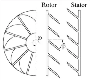
This study employs a VOITH R133-2 hydraulic retar-der for both the CFD and experimental analyses, and the main geometrical parameters of which are listed in Table 1. Specifically, oil inlets and oil outlets are all located on the stator. When the rotor blade lean direc-tion is in accordance with the rotadirec-tion direcdirec-tion, it is denoted here as a front blade lean. A front lean angle contributes to a higher torque performance. As shown in Figure 1, the rotor lean angle is defined asb, and the stator employed in the retarder has an equivalent lean angle to that of the rotor, which enables a greater blade cavity oil capacity. As for the VOITH R133-2 hydrau-lic retarder, the value for b is 40°. In this study, adja-cent values forbof 35°, 43°, and 45°together with 40° are considered to investigate retarder performance.
Grid-independent analysis and boundary conditions
Due to the inclusion of oil inlets and outlets, the stator has an asymmetrical geometry shape. To balance theTable 1. Main geometrical data for the hydraulic retarder.
Rotor inner/outer torus diameter (mm) 170/292
Rotor blade number 36
Rotor blade thickness (mm) 3
Rotor blade wedge angle (°) 30
Stator inner/outer torus diameter (mm) 170/295
Stator blade number 34
Stator blade thickness (mm) 3/6.5
Stator blade wedge angle (°) 15/30
Stator oil inlet number 10
Stator oil outlet number 6
Stator oil outlet radius (mm) 3.5/5
Stator oil inlet area (mm3mm) 1833.5
convergence time and simulation accuracy, we extracted a full-flow passage model, meshed an unstructured grid, and conducted a grid-independent analysis of the calcu-lated retarder torque. From Figure 2, we can see that the deviation of the calculated rotor torque varies by less than 3% for a cell element number of about 1.773106. Finally, about 1.83 106 cells were employed in the simulations. Figure 3 gives a general view of rotor and stator meshes.
The oil viscosity is always a crucial factor that greatly influences hydraulic retarder braking perfor-mance, and it is very sensitive to the temperature. Jilin University conducted a viscosity–temperature charac-teristic analysis of hydraulic oil for the retarder and obtained the dynamic viscosityfv(Pa s) as a function of the oil temperaturexT (°C) by fitting the experimental data, which was expressed by a quadratic variation as follows27
fn(xT) =0:000005x 2
T0:0011xT+0:0666 ð1Þ
As such, the viscosity can be calculated according to the above function based on a known working temperature.
The pressure control valve of the VOITH R133-2 hydraulic retarder, which is a key component for the hydraulic retarder, was tested for the purpose of appropri-ately setting the numerical simulation boundary conditions. It was found that there were four distinct output air pres-sure values, which respectively correspond to four fixed tor-que shifting positions because different air pressures charge different amounts of oil into blade working cavity.
In this study, hydraulic retarder performance for dif-ferent values ofbis investigated with regard to different rotor speeds. All simulations are conducted under steady-state conditions, and the oil viscosity is treated as a constant value. Heat conductivity, heat convection, and heat transfer are ignored. The simulation is per-formed by ANSYS FLUENT code. The single-phase flow condition is considered in this study, which there-fore assigns the pressure inlet as the inlet boundary set-ting, and the value of the inlet pressure is the maximum air pressure output from the control valve. Outflow is imposed for the outlet. Standard k-epsilon turbulence model with standard wall function is used to model the turbulence, for its low computational requirements and good prediction of pressure-related parameters in pump simulation.28 The numerical calculation is conducted based on semi-implicit method for pressure linked equa-tions-consistent (SIMPLEC) arithmetic with second-order upwind format for pressure velocity coupling.29
Simulation validation
To validate the numerical approach, we compared our computed results with results obtained experimentally. Figure 1. Schematic of the rotor and stator of the hydraulic
retarder.
Figure 2. Grid-independent analysis with respect to the calculated rotor torque.
A test rig for the VOITH R133-2 hydraulic retarder with a 40° blade lean angle was established at Jilin University.30 As illustrated in Figure 4, a motor was employed to regulate the rotor rotational speed, com-pressed air for oil control was supplied by an air pump, and torque was measured by a torque speed tach-ometer. In the test rig, a motorized pump and an engine radiator together with a fan were utilized to simulate the water cooling system. Because the hydrau-lic retarders used for both the experimental testing and simulation are of equivalent design, the experimentally obtained braking torque was used to validate the simu-lation results forb= 40°.
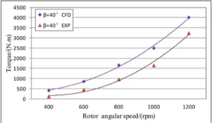
As shown in Figure 5, the torque–rotational speed curves obtained from experiment and simulation exhi-bit an equivalent variation tendency, although the experimental values are generally smaller than the simulation results. This difference is because the simula-tion employs numerous simplificasimula-tions such as the removal of geometry fillets and the neglect of tempera-ture variation. Moreover, some leakage losses and mechanical friction losses that occur during the actual experiment are also not considered in the simulation. In addition, the CFD results forb= 40° also fit the per-formance curve given in the VOITH R133-2 hydraulic retarder product specification very well.31 Hence, the simulation results are considered reasonably accurate.
Results and discussion
Performance curve analysis
The primary purpose of a hydraulic retarder is to gen-erate torque. Therefore, torque performance is the most important factor. Because the rotor is directly con-nected to driveshaft, we calculate the torque generated on the rotor as representative of the hydraulic retarder braking torque.
As mentioned earlier, the temperature has a substan-tial influence on the oil viscosity. Because the hydraulic Figure 4. Schematic of the hydraulic retarder test rig
employed in the experiment.
Figure 5. Comparison of numerical and experimental results.
Figure 6. Schematic of hydraulic retarder oil circulation.
Figure 7. Simulated performance curves of hydraulic retarder for different blade lean anglesb.
retarder transfers mechanical energy to heat energy, the oil temperature quickly rises at the beginning of opera-tion, resulting in a dramatic decrease in the viscosity. Moreover, an excessively high temperature can damage the seal components. Both low viscosity and seal dam-age negatively impact retarder performance. It is there-fore essential to evaluate the cooling performance of a hydraulic retarder system. While the simulations treat the oil viscosity as a constant, and heat conductivity, heat convection, and heat transfer are ignored, hydrau-lic retarder system design involves other aspects that substantially impact the cooling performance, which are considered in the simulations as follows. Figure 6 illustrates the hydraulic retarder oil circulation system. The outer loop oil volume flow rate Q is an
independent parameter that is mainly determined by the dimensional structures of the retarder. A suitable value forQmust be considered during the design pro-cess to ensure that sufficient heat energy can be trans-ferred from the oil in the working cavity to the heat exchanger, which can then be dissipated by the heat exchanger coolant. Herein, we define the value ofQat the oil inlets as a factor to represent retarder oil exchange capacity.
T=lrgv2D5 ð2Þ
where l is the torque coefficient,r is the density,g is gravitation acceleration, and Dis the outer torus dia-meter. We observe from Figure 7 that with increasing
b, Tfirst increases and then decreases. A similar pat-tern is observed forQ. We note that the largest values ofTandQare obtained forb= 43°.
Flow field analysis
The fluid flow inside the passage is very complex; there-fore, this study mainly analyzes conditions on the mid-chord surface with consideration of oil inlets. To enable
a fair comparison for different values ofb, the follow-ing numerical result cases were all computed for
v= 1200 r/min.
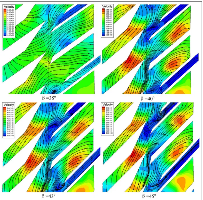
Figure 8 illustrates the static pressure distribution for different values of b on mid-chord surface. As shown in the figure, the meridian wall curvature and centrifugal force make a lower pressure level at the interface than at the bottom wall, which gradually changes along the streamwise direction, and as a func-tion of blade loading. In addifunc-tion, the pressure side has a generally greater pressure than that of suction side. The pressure contours are warped in the circumferen-tial direction due to the blade lean. The rotor and sta-tor exhibit similar pressure distributions. The results Figure 9. Streamlines and velocity contours on the mid-chord surface for different lean anglesb.
demonstrated that the average pressure is greatest for
b= 43°for both the rotor and stator, and a high pres-sure is benefit for the increasing of outer loop oil vol-ume flow rate.
Streamline analysis can be used to investigate sec-ondary vortex flows in the passage. Figure 9 presents the plotted streamlines for the four different values ofb
on the mid-chord surface. The color maps in the back-grounds display the velocity contours. It is noted that the pressure on the outer wall surface is greater than the operating air pressure output from the valve. Some extent of reverse flow may be observable for relatively low values of b, like that shown for b= 35°, which negatively impacts oil exchange. Secondary vortex flows are also clearly observed in low velocity regions. This could be explained by the accumulation of low momentum oil in the inlet structure/end-wall corner. Because the hydraulic retarder functions in a manner similar to that of the stall condition of torque conver-ters, owing to the large attack angle, a large area of flow separation is observed on the upper surface of sta-tor blades. The phenomenon is more obvious for small values of b. For b= 40° and 43°, the flow is better oriented regardless of low velocity regions. However, a more intense velocity gradient is observed forb= 43°, making this blade lean angle more suitable.
Energy loss analysis
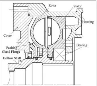
Unlike pumps and torque converters, the efficiency of a hydraulic retarder is zero because of the stator. However, from the viewpoint of energy, a hydraulic retarder transfers the power input of the driveshaft into heat energy within the oil. During the energy conver-sion process, the retarder also suffers some mechanical loss, volume loss, and hydraulic loss. As shown in Figure 10, rotor is connected to the driveshaft with a hollow shaft with internal splines, which must involve some mechanical friction during operation. In addition, because of the different outer torus diameters and the approximately 2-mm axial spacing between rotor and stator, as well as some sealing elements, the oil escapes through the clearances. While this is advantageous for mechanical lubrication, it also results in leakage loss. As such, the oil flowing from the oil inlets does not completely flow out of the oil outlets, and this could be a major source of energy loss. Moreover, secondary vortex and separation flow could also cause hydraulic loss. Finally, because the length of the blade flow pas-sage greatly increases with increasing b, larger blade lean angles increase the hydraulic frictional loss on the wall surface. All these factors influence hydraulic retar-der performance.
Conclusion
This work presented the results of CFD research regarding the performance of a hydraulic retarder with different blade lean anglesbof 35°, 40°, 43°, and 45°. Performance curves of braking torque and outer loop oil flow rate with respect to rotor rotational speed were investigated. Besides, based on the static pressures, velocity contours, and streamlines obtained on the mid-chord surface, an oil flow description analysis was conducted. Finally, an energy loss analysis for the hydraulic retarder was discussed based on the assembly structures of hydraulic retarder components. According to the above analysis, some main results can be con-cluded as follows:
1. With increasingb, both the braking torque and the outer loop oil flow rate first increased and then decreased, providing maximum values for both parameters at b= 43°, which means a higher braking and heat transfer performance. 2. Due to the blade lean, the pressure contours are
warped in the circumferential direction. The average static pressure was observed to be greatest for b= 43°. Larger values of b were observed to improve the occurrence of separate flow, whereas smaller values of b may cause some extent of reverse flow in the oil inlet region. Secondary vertex flows were observed in the low velocity regions. Analysis of the stream-lines indicated that the oil flows are smoother and better oriented forb= 43°, and the velocity gradient is also more intense.
3. Dimensional differences between rotor, stator, and housing resulted in major leakage loss, although this condition is also beneficial for lubrication. In addition, frictional loss was found to increase with increasingb.
The results of this study indicate that at an optimal blade lean angle of around 43°, the hydraulic retarder would simultaneously achieve the best torque perfor-mance, fluid flow, and cooling performance. As such, this study provides a theoretical basis for further opti-mization work.
Declaration of conflicting interests
The author(s) declared no potential conflicts of interest with respect to the research, authorship, and/or publication of this article.
Funding
The author(s) received no financial support for the research, authorship, and/or publication of this article.
References
1. Go¨hring E, von Glasner EC and Povel R. Engine brak-ing systems and retarders—an overview from an Eur-opean standpoint. SAE technical paper 922451, 1992. 2. Brun K, Flack RD and Gruver JK. Laser velocimeter
measurements in the turbine of an automotive torque converter: part II—unsteady measurements.J Turbomach 1997; 119: 655–662.
3. Brun K and Flack RD. Laser velocimeter measurements in the pump of an automotive torque converter: part II—unsteady measurements. J Turbomach 1996; 118: 570–577.
4. McKinnon CN, Brennen D and Brennen CE. Hydraulic analysis of a reversible fluid coupling.J Fluid Eng2001; 123: 249–255.
5. Bois G, Bayeul AC and Leclerc C. Numerical torque converter performance predictions: validation and appli-cation to a rapid one dimensional approach. In:FEDSM 2005 conference, Houston, TX, 19–23 June 2005, Paper no. FEDSM2005-77039. New York: ASME.
6. Liu S and Quan L. Mathematical model of hydraulic tor-que converter and analytic description of streamline. Chin J Mech Eng2009; 22: 70–77.
7. Kesy A and Kadziela A. Application of statistical formu-las to hydraulic torque converter modeling. Arch Civ Mech Eng2009; 9: 33–48.
8. Manea A, Dobaˆnda˘ E and Babic M. Theoretical and experimental studies on torque converters. Therm Sci 2010; 14: 231–245.
9. Bai L, Fiebig M and Mitra NK. Numerical analysis of turbulent flow in fluid couplings.J Fluid Eng1997; 119: 569–576.
10. Dong Y, Lakshminarayana B and Maddock D. Steady and unsteady flow field at pump and turbine exits of a torque converter.J Fluid Eng1998; 120: 538–548.
11. Flack R and Brun K. Fundamental analysis of the sec-ondary flows and jet-wake in a torque converter pump— part I: model and flow in a rotating passage.J Fluid Eng 2005; 127: 66–74.
12. Flack R and Brun K. Fundamental analysis of the sec-ondary flows and jet-wake in a torque converter pump— part II: flow in a curved stationary passage and combined flows.J Fluid Eng2005; 127: 75–82.
13. Stel H, Amaral GDL, Negra˜o COR, et al. Numerical analysis of the fluid flow in the first stage of a two-stage centrifugal pump with a vaned diffuser.J Fluid Eng2013; 135: 071104.
14. Wang W and Wang Y. Analysis of inner flow in low spe-cific speed centrifugal pump based on LES.J Mech Sci Technol2013; 27: 1619–1626.
15. Talukder SA and Huynh BP. Effects of number of stator blades on the performance of a torque converter. In: IMECE 2011 conference, ASME, Denver, CO, 11–17 November 2011, pp.949–953. New York: ASME. 16. Yang SS, Kong FY, Chen H, et al. Effects of blade wrap
angle influencing a pump as turbine. J Fluid Eng2012; 134: 061102.
17. Shin S, Kim KJ, Kim DJ, et al. The effect of reactor blade geometry on the performance of an automotive torque converter. SAE technical paper 2002-01-0885, 2002. 18. Chunxi L, Ling WS and Yakui J. The performance of a
centrifugal fan with enlarged impeller. Energ Convers Manage2011; 52: 2902–2910.
19. Yang SS, Kong FY, Jiang WM, et al. Effects of impeller trimming influencing pump as turbine. Comput Fluids 2012; 67: 72–78.
20. Jain SV, Swarnkar A, Motwani KH, et al. Effects of impeller diameter and rotational speed on performance of pump running in turbine mode. Energ Convers Man-age2015; 89: 808–824.
21. D’Ippolito G, Dossena V and Mora A. The influence of blade lean on straight and annular turbine cascade flow field.J Turbomach2011; 133: 011013.
22. Harrison S. The influence of blade lean on turbine losses. J Turbomach1992; 114: 184–190.
23. Choi WC, Yoo IS, Park MR, et al. Experimental study on the effect of blade angle on regenerative pump perfor-mance.Proc IMechE, Part A: J Power and Energy2013; 227: 585–592.
24. Oh JS, Buckley CW and Agrawal GL. Numerical study on the effects of blade lean on high-pressure centrifugal impeller performance. In:ASME 2011 turbo expo: Tur-bine technical conference and exposition, Vancouver, BC, Canada, 6–10 June 2011, pp.1957–1969. New York: ASME.
25. He R and Yan J. Performance analysis for hydrodynamic retarder with different vanes.Trans Chin Soc Agric Mach 2009; 40: 206–209.
26. Li X, Liu C, Cheng X, et al. Cascade angle optimization of hydraulic retarder based on flow field characteristics. Trans Chin Soc Agric Mach2014; 45: 20–24.
27. Liu C, Xu D, Ma W, et al. Analysis of unsteady rotor– stator flow with variable viscosity based on experiments and CFD simulations.Numer Heat Tr A: Appl2015; 68: 1351–1368.
28. Feng J, Benra FK and Dohmen HJ. Application of dif-ferent turbulence models in unsteady flow simulations of a radial diffuser pump. Forsch Ingenieurwes 2010; 74: 123–133.
29. Cui B, Wang C, Zhu Z, et al. Influence of blade outlet angle on performance of low-specific-speed centrifugal pump.J Therm Sci2013; 22: 117–122.
30. Wang T.Research on simulation method for analysis on three-dimension flow field of automotive hydraulic retarder. MSc Thesis, Jilin University, Changchun, China, 2007. 31. Greater safety less cost: Retarder VR 133-2, http://voith.