Preliminary analysis of knee stress in Full Extension
Landing
Majid Davoodi Makinejad,INoor Azuan Abu Osman,IWan Abu Bakar Wan Abas,IMehdi BayatII
IUniversity of Malaya, Faculty of Engineering, Department of Biomedical Engineering, Kuala Lumpur, Malaysia.IIAalborg University, Department of Civil Engineering, Aalborg, Denmark.
OBJECTIVE: This study provides an experimental and finite element analysis of knee-joint structure during extended-knee landing based on the extracted impact force, and it numerically identifies the contact pressure, stress distribution and possibility of bone-to-bone contact when a subject lands from a safe height.
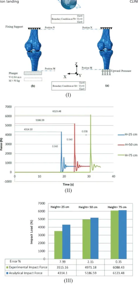
METHODS:The impact time and loads were measured via inverse dynamic analysis of free landing without knee flexion from three different heights (25, 50 and 75 cm), using five subjects with an average body mass index of 18.8. Three-dimensional data were developed from computed tomography scans and were reprocessed with modeling software before being imported and analyzed by finite element analysis software. The whole leg was considered to be a fixed middle-hinged structure, while impact loads were applied to the femur in an upward direction.
RESULTS:Straight landing exerted an enormous amount of pressure on the knee joint as a result of the body’s inability to utilize the lower extremity muscles, thereby maximizing the threat of injury when the load exceeds the height-safety threshold.
CONCLUSIONS: The researchers conclude that extended-knee landing results in serious deformation of the meniscus and cartilage and increases the risk of bone-to-bone contact and serious knee injury when the load exceeds the threshold safety height. This risk is considerably greater than the risk of injury associated with walking downhill or flexion landing activities.
KEYWORDS: Force of Impact; Full Extension Landing; Contact Force; Knee Cartilage Injury; Knee Components; Finite Element Analysis.
Makinejad MD, Abu Osman NA, Wan Abas WAB, Bayat M. Preliminary analysis of knee stress in Full Extension Landing. Clinics. 2013;68(9):1180-1188.
Received for publication onFebruary 10, 2013;First review completed onMarch 10, 2013;Accepted for publication onApril 4, 2013 E-mail: [email protected]
Tel.: 006 03 7967 6871
& INTRODUCTION
Extended-knee landing applies a significant impact load on the limited contact area of the knee components, thereby causing great stress and increasing the risk of injury. Approximately five million people visit orthopedic sur-geons annually because of knee problems, and approxi-mately 1.1 million people are admitted to hospital emergency rooms as a result of knee injuries caused by unusual activities (1). The human knee is capable of bearing loads of up to 2.5 times body weight (BW) while walking and more than 12 times BW while running and jumping (2). During knee flexion while landing, the muscular system acts as the primary active absorption mechanism; however,
the tibia-fibula plays the most important role in dampening the impact (3-5). In contrast, during extended-knee landing, the insufficiency of energy dissipation produced by the body’s lower extremity muscles is coupled with the excessive ground reaction force (GRF). The GRF increases the impact stress and aggravates the risk of injury when landing from a particular height (2,6-10). The knee acts as the primary shock absorber in bilateral foot landing, whereas the ankle and hip extensors are the second largest contributors to the absorption of energy (11). The greater magnitudes of GRF, peak posterior shear stress and knee co-contraction index occur between the 0
˚
and 25˚
knee flexion landing positions (12-14). At the same time, the risk of knee damage increases during extended-knee landing because of the lack of energy dissipation in the lower extremities, which in turn causes significant compressive fracture loads during this type of landing (15-17).Voigt et al. (16) studied the muscular and mechanical parameters in maximal vertical jumping performance. Selbie and Caldwell (17) investigated the effects of different postures on the amount of force applied to the knee joint. The majority of earlier studies investigated the final stress
Copyrightß2013CLINICS– This is an Open Access article distributed under the terms of the Creative Commons Attribution Non-Commercial License (http:// creativecommons.org/licenses/by-nc/3.0/) which permits unrestricted non-commercial use, distribution, and reproduction in any medium, provided the original work is properly cited.
No potential conflict of interest was reported.
and the effects of other parameters on the entire moving mechanism as an integrated dynamic system, which included the muscles and ligaments in contact forces (18-21). The effects of all of these parameters on the knee contact pressure complicate the calculation. Kuster et al. (22) reported that three effective parameters (i.e., bone-to-bone contact, muscle force and GRF) exhibited pressures equal to eight, six and two times BW, respectively, during downhill walking. However, only a limited number of investigations have studied the risks of knee-joint injuries as the result of performing activities that involve a flexed knee (1,15,23). The current study analyzed possible deformations that can lead to bone-to-bone contact and, subsequently, to the risk of serious injuries to the knee joints as a result of extended-knee landing.
This study used experimental and numerical methods to identify the critical impact force on the knee joints during extended-knee landing from threshold heights. Finite ele-ment analysis (FEA) ABAQUS software (ABAQUS Inc., 108 Providence, RI, USA) was used to identify the contact areas and the effects of stress on the meniscus, tibial and femoral cartilage after, landing based on the extracted force from the experimental data. Moreover, FEA was used to analyze the contact pressure variations and stress distributions of the main deformable knee components. The results revealed a significant deformation in the components of the knee joints during landing, which increased the risk of bone-to-bone contact during extended-knee landing. The values of stress and impact force could be applicable to the unpredictable conditions of several sporting activities, such as skydiving and skiing on water and snow. Moreover, threshold stress could be considered when designing methods to enhance the performance of artificial knee materials.
& MATERIALS AND METHODS
Experimental analysis
Experimental data were collected at the Motion Analysis Laboratory of the Faculty of Engineering of the University of Malaya. The university’s ethics committee approved the study, and all of the subjects provided written informed consent. A physical therapist from the university sports department verified that the selected five subjects were physically healthy and had no history of lower limb joint injury or instability. The subjects had an average weight of 64 kg, average BMI of 18.8 and average age of 24 years and 8 months old. Each subject landed on a force plate from three different heights (25, 50 and 75 cm), and five individual trials were performed for each height. Vertical impact loads and time were measured and compared via analytical examination. One-way repeated measures ANOVA was used to evaluate the effects of landing from the three heights. Prior to the test, the subjects warmed up by cycling for 10 minutes with a low workload. Following the warm-up, the subjects performed double-flexion landings on the force plate from the predetermined heights. Both knee joints of each subject were braced using a Contender Knee Brace (Corflex, UK) to ensure that the knee hinge was fixed in full extension, to prevent any unintentional flexion and to maintain the knee in a straight position during landing. The landing force, impact period (the interval between the time the subjects touched the ‘‘Kistler’’ force plate and the maximum load) and velocity were recorded for every trial. Markers were attached to the subjects at various locations
on their body according to the Helen Hayes (Davis) marker placement system. The cameras (Vicon), force plate (Kistler) and markers were calibrated prior to the testing. Body motion was captured upon landing using seven infrared calibrated cameras that recorded data at a frequency of 200 Hz. The results were analyzed using Vicon Nexus 512 software (Figure 1).
Theoretical analysis
The peak vertical ground reaction force (N) and the impact time (ms) were recorded for every landing. Moreover, the impact time and force were theoretically calculated and were compared with the corresponding experimental results. Given that the maximum distance (75 cm) caused the highest landing velocity and greater risk of more serious injury, this velocity was determined using Equation 2.1:
V2{V02~2gx:
V0andVrefer to the initial and final speed of the subject (m/s), respectively, when standing on the platform and having finally touched the force plate,gis equal to 9.8 m/s
2, andxis the height in meters. The force was determined
from Equation 2.2, while the timing was extracted from the maximum heights of the jump:
ðt
0
F dt~ ðV
0
m dv:
As part of the preliminary FEM analysis, the desired experimental data (impact load and timing) were applied to the developed three-dimensional (3D) model using the FEA software. Dynamic explicit analysis was used to calculate the contact pressure and stresses during extended-knee landing. The data analysis process that was applied in this study is presented in Figure 2.
Geometry development
A geometric 3D data model was developed by obtaining 2D images of the whole leg using a computed tomography (CT) scan (Siemens Somatom Sensation 16). The resulting data were developed at 0
˚
flexion, based on the scanned images of the entire leg of a 24-year-old subject. The volumetric 3D images of both legs consisted of parallel digital images with a 0.539 mm slice thicknesses on the sagittal, coronal and axial planes, each of which was measured by an in-plane pixel resolution of 512 pixels6512 pixels. The 2D images were converted to 3D surface
models using MIMICS software. GEOMAGIC STUDIO (version 11.7) was used to convert the resultant triangular meshes from MIMICS into a smooth, non-uniform, rational B-spline (NURBS) surface. Thereafter, the knee components were imported into ABAQUS FEA software.
Knee structure simulation
The human knee has complex geometries, and adequately modeling this joint can be significantly challenging (24,25). The knee was placed in a closed-packed position (lock position) during extended landing, which minimized the possibility of rotation and increased the rigidity, to transfer
CLINICS 2013;68(9):1180-1188 Knee stress in full extension landing
the energy to the knee (26,27). This position is usually at the extreme end of the range of motion (ROM), in which the joint surfaces are maximally congruent, whereas the ligaments and capsules provide the greatest stability against tensile forces and are completely taut (28,29). Landing with the bilateral braced knee confines the knee’s side move-ments and causes the landing force to pass through the knee-joint components and compress the distance between the tibia and the femur. A developed safety mechanism was added to the brace. It unclasped if the load extended beyond the threshold and did not allow the subjects to be injured. The ACL only reacts under tension loading and cannot withstand axial compression force; consequently, it could be omitted in the compression FE analysis. In flexion landing, the contribution of the muscles to the dissipation of kinetic energy decreases through the reduction of the flexion angle; the minimum contribution corresponds to a 0
˚
flexion angle (23,30). The inability of the lower extremity muscles to dampen the impact load adequately during full-extension landing causes major impact load transfer to the knee-joint components. In the current study, the poor contribution of muscles toward dampening the landing force was deduced from the total applied load in the FEA simulation. A simplified fixed-hinge mechanism was chosen to simulate the behavior of the whole leg in extended-knee landing (Figure 1-b). The instant load was applied in an upward direction, while the rotation of the knee (middle-hinged) was fixed (Figure 3-I-a).Material and boundary conditions
The behavior of the knee-joint components (meniscus and cartilage) changes according to the analysis condition
(i.e., the type [static or dynamic], load direction [tension or compression] and loading time) (31). This behavior complicates the identification of the exact material behavior from the predefined material FEA model. The biphasic (solid and fluid) and time-dependent behaviors of the meniscus and cartilage depend on both the magnitude and rate of loading (32). In the present study, instant loading (Figure 3-II) did not allow the meniscus or cartilage to reach the fluid phase and present their viscoelastic behaviors, wherein the impact load is less than 1 s (33). Thus, the mechanical properties of the solid phase were considered to be biphasic (34,35). Given that extreme strain occurs in the
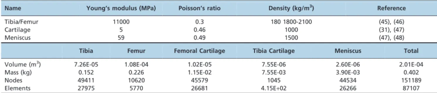
Z-direction (other directions were confined), the mechanical analyses were determined in the vertical direction (36). The material behaviors of the tibia, femur, meniscus and cartilage were assumed to be isotropic linear elastics (37,38). Their properties were derived from the existing literature (Table 1-I).
Two methods were adopted in this study for the purpose of a free-falling dynamic impulse load simulation. In the first case (Figure 3-I-a), an equivalent instant load was applied in an upward direction from the excised tibia during full extension. The femur was considered to be constrained fully (six degrees of freedom), whereas the tibia moved in a vertical direction to transfer the impact load to the entire structure. The surface-to-surface contact among the tibia plateau cartilage, articular cartilage and meniscus was defined as a tie; their movements were simultaneously confined, with the exception of the vertical direction. Both the proximal femur and the distal tibia were fully fixed. In the second case (Figure 3-I-b), a plunger with a weight equal to the subject’s mass and landing velocity
(velocity when the subject touched the force plate, Equation 1) occurred in theZdirection to theMposition of the tibia, to duplicate the same landing force that was produced during landing.
The applied pressure on the tibia was 14 MPa, and the cross-sectional area of the cut tibia was 381.83 mm2, which corresponded to an applied force that was almost 11 times BW. The finite element data of the knee components are summarized in Table 1-II.
& RESULTS
Experimental and theoretical impact force
The applied load on the feet during free landing varies according to the height, ground softness, footwear softness, joint flexion, landing positions and direction. Three different vertical landings are illustrated in Figure 3-II. The magni-tude of the load was increased via height increments, whereas the impact time decreased. Considering that no significant differences were found among the falling periods from various heights, the impact time (impact duration) was quite short. Therefore, an average time of 0.04 s was applied in the analysis. The landing lag time was 20 s (subject’s delay time in every landing), but to obtain appreciable
graph clarification, a 5-s lag time was added to each landing time until the point at which the fluctuation of the subsequent landing was stabilized in terms of BW. The velocity of the subject during free-fall from a height of 75 cm could be estimated using Equation 3.1:
V2
{V02~2gx
V tð Þ~pffiffiffiffiffiffiffiffiffiffiffiffiffiffiffiffiffiffiffiffiffiffiffiffiffiffiffiffi2x9:806x0:75
V~3:835m=s:
The average impact time derived during the experimental test was equal to 0.04 s. This time allows that the impact load to be identified using the following equation:
ðt
0
Fdt~
ð3:835
0
mdv
F~6136N:
Figure 2 -General part development and finite element analysis flowchart.
CLINICS 2013;68(9):1180-1188 Knee stress in full extension landing
The values of the average theoretical, experimental impact forces and error percentages across the five trials are similar to those shown in Figure 3-III.
Stress and contact pressure distribution
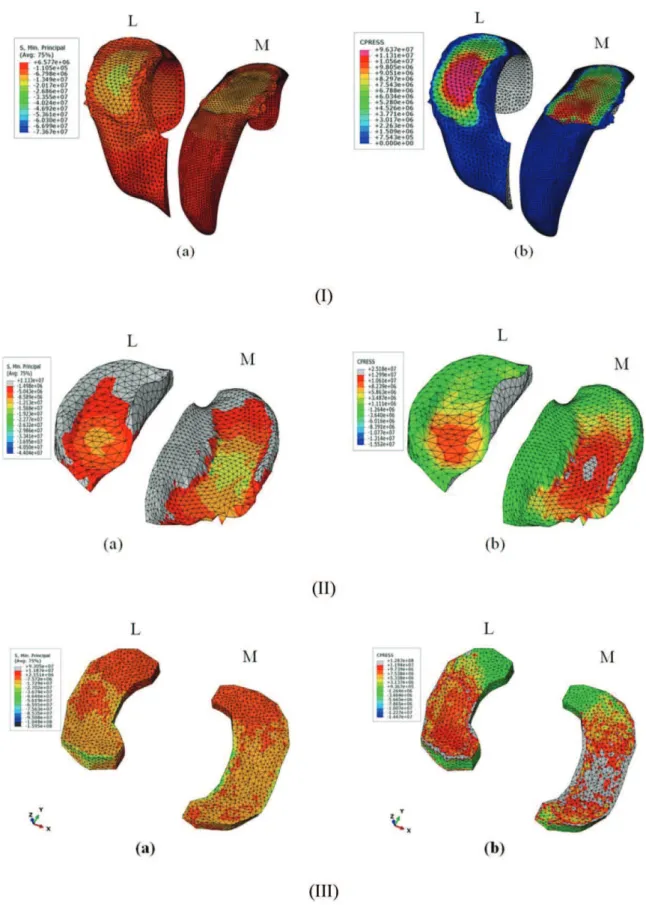
The stress distribution and contact pressure of the femoral cartilage during extended-knee landing, with an impact load from a height of 75 cm, are shown in Figures 4-I-a and b, respectively. At a pressure of -13.5 MPa, the compressive stress on the lateral femoral cartilage was greater than that on the medial cartilage, which was recorded at -6.8 MPa. Moreover, the peak nodal stress of -60.3 MPa on the penetrated wall in the lateral area was greater than that in the medial area (-46.9 MPa). Both tail sides carried a stress value of+6.6 MPa. As illustrated in Figure 4-I-b, the sections in which a pressure of 96.4 MPa was applied at the center of the convex area in the lateral femoral cartilage were considerably larger than the medial sections, with the stressed area at 11.3 MPa.In addition, the pressure around
the penetrated wall on both sides was observed at 2.3 MPa. The instant load was applied in 0.04 s, which caused significant deformation. The convex shape of the femoral cartilage allowed for fewer contact points and caused high
-compression stress deformation. In addition, the defined material model might not have fully supported the real viscoelastic behavior of the cartilage to show smooth energy absorption during the impact load.
The compressive stress on the tibial cartilage is depicted in Figure 4-II-a. The femoral cartilage was notably the first knee-joint component exposed to the impact force (upward load). Therefore, this component absorbed the greatest impact. As such, the penetration and stress concentration must have been higher in the femoral cartilage. The medial tibial cartilage (12.1 MPa) was similarly found to have withstood more stress than the lateral cartilage (8.6 MPa). Furthermore, the pick nodal stress value of the medial cartilage in the penetrated wall was 33.4 MPa. Given that the Young’s modulus of the meniscus is approximately 10 times that of the cartilage, cartilage deformation should be greater than that of the meniscus when transmitting the impulse load. As demonstrated in Figure 4-II-b, the contact pressure in the medial cartilage was greater than that in the lateral cartilage, thus producing greater pressure on the medial cartilage (25.2 MPa) than on the lateral cartilage (13.0 MPa).
The contact area of the medial meniscus was much greater than that of the lateral meniscus, and the peak value of the contact area was observed at 56.19 and 7.57 MPa on the peripheral and central areas, respectively (Figure 4-III-a). The peak contact pressure value was recorded at 128.7 MPa, with an average of 11.94 MPa, whereas the peak
contact area on the anterior of the lateral meniscus was recorded at an average pressure of 9.739 MPa (Figure 4-III-b).
This contact pressure caused depressions among the tibial cartilage, femoral cartilage and meniscus. This depression was measured between two nodes before and after the maximum height landing. The contact pressure during the first landing height was 23.1 MPa, which increased to 128.7 MPa for the last landing height. The depression percentage (Dl, contraction of knee-joint components) was approximately 48%. Previous studies have revealed that significant injuries can occur if the distance between the tibia plateau and the femoral condyle decreases by up to 50% of its normal distance (29,39). The knee during this test approached the lower limit for the incidence of significant injuries (Figure 5).
& DISCUSSION
This study focused on FEA and a simulation model of human legs during free-fall extension landing with the aim of identifying the critical stress distributions and contact pressure on the knee components. The results indicate that the applied impact loads during extended-knee landing were relatively greater than they were during knee flexion during landing (28,40). Several studies have indicated that the greatest fracture stress can occur as a result of repetitive impact stress, which is induced during running activities (15,26,41). However, the stress measured during extended-knee landing was far greater than that produced during running activities and that the stress was applied instantly might have resulted in serious damage. As such, safety factors should be considered for all predicted critical conditions (42) to offer more reliable structures for artificial knee components.
The maximal stability and greatest risk of injury occur when the knee joint locks in full extension during an upright standing position (13,39,43). However, the femoral condyles roll and glide in their contact positions and act as a hinge that serves to decrease direct knee-impact force. If the impact loads had been applied directly to the tibia without considering knee flexion and bone buckling, the results would have been high stress, deformation and pain. People bend their knees unintentionally during landing to trans-form the direct load to moment, which allows the impact to be dampened by the muscles, instead of the knee structure. The impact force during landing is extremely high, causing the corresponding high deflection in the vertical direction to exceed the threshold stress (maximum tolerable stress), which causes contact between the tibia and the femur.
Table 1 -(I) The mechanical property of knee components. (II) Knee component’s finite element data.
Name Young’s modulus (MPa) Poisson’s ratio Density (kg/m3) Reference
Tibia/Femur 11000 0.3 180 1800-2100 (45), (46)
Cartilage 5 0.46 1000 (31), (47)
Meniscus 59 0.49 1500 (47), (48)
Tibia Femur Femoral Cartilage Tibia Cartilage Meniscus Total
Volume (m3) 7.26E-05 1.08E-04 1.02E-05 7.55E-06 2.60E-06 2.01E-04
Mass (kg) 0.152 0.226 1.15E-02 7.55E-03 3.90E-03 0.402
Nodes 49411 10620 45579 1045 44534 151189
Elements 27975 5770 26681 4.15E+02 26266 87107
CLINICS 2013;68(9):1180-1188 Knee stress in full extension landing
Furthermore, the central mass of the human body produces a moment, which causes the knee to react by bending. Nigg et al. (6) discussed the observed maximum flexion during jumping activities. Piazza et al. and Kuster et al. (22,44) illustrated that the impact load during flexion while walking downhill was shared by three types of reaction force: bone-to-bone compressive force, muscle force and GRF, with pressures equal to eight, six and two times BW, respectively. During extended-knee landing, the majority of the force is dampened by bone-on-bone contact and GRF. This force is significantly greater than that demonstrated during flexion landing. The off-centricity of the center of mass of the human body can cause the tibia to rotate after landing to stabilize the body.
In the present study, the severity of extended-knee landing was investigated. Significant deformation occurs within the knee components, meniscus and cartilage during full-exten-sion landing as the result of a lack of energy dissipated in the lower extremity. This state increases the risk of bone-on-bone contact and knee injury. This risk is considerably greater than the risk of injury associated with walking downhill or flexion landing activities. The computed stress value could be of use in artificial knee components or in the geometrical design of these components, which could be used in related industries and in future studies.
& ACKNOWLEDGMENTS
This research was supported by a Malaysia UM/MOHE/HIR grant (project no. D000010-16001).
& AUTHOR CONTRIBUTIONS
Makinejad MD conducted the experimental and FE analysis and data analysis and assisted in writing the manuscript. Abu Osman NA was the main investigator of the project, prepared the experimental facilities and edited the manuscript. Wan Abas WAB was the co-investigator of the project and prepared the testing facilities. Bayat M assisted the author with the FE analysis and in writing the manuscript.
& REFERENCES
1. Million A Year Seek Medical Care For Knees [Internet]. AAOS 1997. Available from: http://www.arthroscopy.com/sp13008.htm.
2. Rees J, Wilson A, Wolman R. Current concepts in the management of tendon disorders. Rheumatology. 2006;45(5):508-21, http://dx.doi.org/ 10.1093/rheumatology/kel046.
3. McNitt-Gray J. Kinetics of the lower extremities during drop landings from three heights. Journal of Biomechanics. 1993;26(9):1037-46, http:// dx.doi.org/10.1016/S0021-9290(05)80003-X.
4. Nigg BM, Liu W. The effect of muscle stiffness and damping on simulated impact force peaks during running. Journal of Biomechanics. 1999;32(8):849-56, http://dx.doi.org/10.1016/S0021-9290(99)00048-2. 5. Zhang S, Bates B, Dufek J. Contributions of lower extremity joints to energy
dissipation during landings. Medicine & Science in Sports & Exercise. 2000;32(4):812-9, http://dx.doi.org/10.1097/00005768-200004000-00014. 6. Nigg BM, MacIntosh BR, Mester J. Biomechanics and biology of
movement: Human Kinetics Publishers; 2000.
7. Dufek J, Bates B. Biomechanical factors associated with injury during landing in jump sports. Sports medicine (Auckland, NZ). 1991;12(5):326-37.
8. Yeow C, Lee PVS, Goh JCH. Regression relationships of landing height with ground reaction forces, knee flexion angles, angular velocities and joint powers during double-leg landing. The Knee. 2009;16(5):381-6, http://dx.doi.org/10.1016/j.knee.2009.02.002.
9. Moglo K, Shirazi-Adl A. Biomechanics of passive knee joint in drawer: load transmission in intact and ACL-deficient joints. The Knee. 2003;10(3):265-76, http://dx.doi.org/10.1016/S0968-0160(02)00135-7. 10. Frobell R, Roos H, Roos E, Hellio Le Graverand MP, Buck R, Tamez-Pena
J, et al. The acutely ACL injured knee assessed by MRI: are large volume traumatic bone marrow lesions a sign of severe compression injury? 1. Osteoarthritis and Cartilage. 2008;16(7):829-36, http://dx.doi.org/10. 1016/j.joca.2007.11.003.
11. Decker MJ, Torry MR, Wyland DJ, Sterett WI, Richard Steadman J. Gender differences in lower extremity kinematics, kinetics and energy absorption during landing. Clinical Biomechanics. 2003;18(7):662-9, http://dx.doi.org/10.1016/S0268-0033(03)00090-1.
12. Dufek J, Bates B. The evaluation and prediction of impact forces during landings. Medicine & Science in Sports & Exercise. 1990;22(3):370-7. 13. Podraza J, White S. Effect of knee flexion angle on ground reaction
forces, knee moments and muscle co-contraction during an impact-like deceleration landing: Implications for the non-contact mechanism of ACL injury. The Knee. 2010;17(4):291-5, http://dx.doi.org/10.1016/j. knee.2010.02.013.
14. Bellemans J, Ries MD, Victor J. Total knee arthroplasty: a guide to get better performance. Heidelberg: Springer; 2005.
15. Radin E, Parker H, Pugh J, Steinberg R, Paul I, Rose R. Relationship between trabecular microfractures and cartilage degeneration. Journal of Biomechanics. 1973;6(1):51-4, http://dx.doi.org/10.1016/0021-9290(73) 90037-7.
16. Voigt M, Simonsen E, Dyhre-Poulsen P, Klausen K. Mechanical and muscular factors influencing the performance in maximal vertical jumping after different prestretch loads. Journal of Biomechanics. 1995;28(3):293-307, http://dx.doi.org/10.1016/0021-9290(94)00062-9. 17. Selbie W, Caldwell G. A simulation study of vertical jumping from
different starting postures. Journal of Biomechanics. 1996;29(9):1137-46, http://dx.doi.org/10.1016/0021-9290(96)00030-9.
18. Hsieh YF, Draganich LF, Ho SH, Reider B. The effects of removal and reconstruction of the anterior cruciate ligament on patellofemoral kinematics. The American Journal of Sports Medicine. 1998;26(2):201-9. 19. Li G, Rudy T, Sakane M, Kanamori A, Ma C, Woo S. The importance of
quadriceps and hamstring muscle loading on knee kinematics and in-situ forces in the ACL. Journal of Biomechanics. 1999;32(4):395-400, http://dx.doi.org/10.1016/S0021-9290(98)00181-X.
Figure 5 -Maximum penetration of the knee joints: a) the distance before landing and b) the distance after landing.
CLINICS 2013;68(9):1180-1188 Knee stress in full extension landing
20. Zajac F. Muscle coordination of movement: a perspective. Journal of Biomechanics; Perth: Elsevier; 1993.p.109-24.
21. Hsieh YF, Draganich L. Increasing quadriceps loads affect the lengths of the ligaments and the kinematics of the knee. Journal of biomechanical engineering. 1998;120(6):750-6, http://dx.doi.org/10.1115/1.2834889. 22. Kuster MS, Wood GA, Stachowiak GW, Gachter A. Joint load
considerations in total knee replacement. Journal of Bone and Joint Surgery-British Volume. 1997;79B(1):109-13, http://dx.doi.org/10.1302/ 0301-620X.79B1.6978.
23. Withrow TJ, Huston LJ, Wojtys EM, Ashton-Miller JA. The relationship between quadriceps muscle force, knee flexion, and anterior cruciate ligament strain in an in vitro simulated jump landing. The American Journal of Sports Medicine. 2006;34(2):269-74, http://dx.doi.org/10. 1177/0363546505280906.
24. Doweidar M, Calvo B, Alfaro I, Groenenboom P, Doblare´ M. A comparison of implicit and explicit natural element methods in large strains problems: Application to soft biological tissues modeling. Computer Methods in Applied Mechanics and Engineering. 2010; 199(25-28):1691-700, http://dx.doi.org/10.1016/j.cma.2010.01.022. 25. Mesfar W, Shirazi-Adl A. Biomechanics of the knee joint in flexion under
various quadriceps forces. The Knee. 2005;12(6):424-34, http://dx.doi. org/10.1016/j.knee.2005.03.004.
26. Fukuda Y, Takai S, Yoshino N, Murase K, Tsutsumi S, Ikeuchi K, et al. Impact load transmission of the knee joint-influence of leg alignment and the role of meniscus and articular cartilage. Clinical Biomechanics. 2000;15(7):516-21, http://dx.doi.org/10.1016/S0268-0033(00)00013-9. 27. Young CC, Niedfeldt MW, Morris GA, Eerkes KJ. Clinical examination
of the foot and ankle. Primary Care-Clinics in Office Practice. 2005;32(1):105-32, http://dx.doi.org/10.1016/j.pop.2004.11.002. 28. Andriacchi TP, Dyrby CO. Interactions between kinematics and loading
during walking for the normal and ACL deficient knee. Journal of Biomechanics. 2005;38(2):293-8, http://dx.doi.org/10.1016/j.jbiomech. 2004.02.010.
29. Papaioannou G, Nianios G, Mitrogiannis C, Fyhrie D, Tashman S, Yang K. Patient-specific knee joint finite element model validation with high-accuracy kinematics from biplane dynamic Roentgen stereogrammetric analysis. Journal of Biomechanics. 2008;41(12):2633-8, http://dx.doi.org/ 10.1016/j.jbiomech.2008.06.027.
30. Engin AE, Tu¨mer ST. Improved dynamic model of the human knee joint and its response to impact loading on the lower leg. Journal of biomechanical engineering. 1993;115(2):137-43, http://dx.doi.org/10. 1115/1.2894113.
31. LeRoux MA, Setton LA. Experimental and biphasic FEM determinations of the material properties and hydraulic permeability of the meniscus in tension. Journal of biomechanical engineering. 2002;124(3):315-21, http://dx.doi.org/10.1115/1.1468868.
32. Wang J-L, Parnianpour M, Shirazi-Adl A, Engin AE. Viscoelastic finite-element analysis of a lumbar motion segment in combined compression and sagittal flexion: Effect of loading rate. Spine. 2000;25(3):310-8, http://dx.doi.org/10.1097/00007632-200002010-00009.
33. Athanasiou KA, Sanchez-Adams J. Engineering the Knee Meniscus: Morgan & Claypool; 2009.
34. Donzelli PS, Spilker RL, Ateshian GA, Mow VC. Contact analysis of biphasic transversely isotropic cartilage layers and correlations with
tissue failure. Journal of Biomechanics. 1999;32(10):1037-47, http://dx. doi.org/10.1016/S0021-9290(99)00106-2.
35. Garcia J, Altiero N, Haut R. An approach for the stress analysis of transversely isotropic biphasic cartilage under impact load. Journal of biomechanical engineering. 1998;120(5):608-13, http://dx.doi.org/10. 1115/1.2834751.
36. Leslie B, Gardner D, McGeough J, Moran R. Anisotropic response of the human knee joint meniscus to unconfined compression. Proceedings of the Institution of Mechanical Engineers, Part H: Journal of Engineering in Medicine. 2000;214(6):631-5, http://dx.doi.org/10. 1243/0954411001535651.
37. Pena E, Calvo B, Martinez M, Palanca D, Doblare´ M. Finite element analysis of the effect of meniscal tears and meniscectomies on human knee biomechanics. Clinical Biomechanics. 2005;20(5):498-507, http://dx. doi.org/10.1016/j.clinbiomech.2005.01.009.
38. Donahue TLH, Hull M. A finite element model of the human knee joint for the study of tibio-femoral contact. Journal of biomechanical engineering. 2002;124(3):273-80.
39. Georgoulis A, Ristanis S, Moraiti C, Paschos N, Zampeli F, Xergia S, et al. ACL injury and reconstruction: Clinical related in vivo biomechanics. Orthopaedics & Traumatology: Surgery & Research. 2010;96(8):S119-S28, http://dx.doi.org/10.1016/j.otsr.2010.09.004.
40. Podraza JT, White SC. Effect of knee flexion angle on ground reaction forces, knee moments and muscle co-contraction during an impact-like deceleration landing: Implications for the non-contact mechanism of ACL injury. The Knee. 2010;17(4):291-5, http://dx.doi.org/10.1016/j. knee.2010.02.013.
41. Simon S, Radin E, Paul I, Rose R. The response of joints to impact loading--II In vivo behavior of subchondral bone. Journal of Biomechanics. 1972;5(3):267-70, http://dx.doi.org/10.1016/0021-9290(72)90042-5. 42. Collins J, Busby H, Staab G. Mechanical design of machine elements and
machines: Wiley; 2009.
43. McLean SG, Lucey SM, Rohrer S, Brandon C. Knee joint anatomy predicts high-risk in vivo dynamic landing knee biomechanics. Clinical Biomechanics. 2010;25(8):781-8, http://dx.doi.org/10.1016/j.clinbiomech. 2010.06.002.
44. Piazza S, Delp S. Three-dimensional dynamic simulation of total knee replacement motion during a step-up task. Journal of biomechanical engineering. 2001;123(6):599-606.
45. Beillas P, Papaioannou G, Tashman S, Yang K. A new method to investigate in vivo knee behavior using a finite element model of the lower limb. Journal of Biomechanics. 2004;37(7):1019-30, http://dx.doi. org/10.1016/j.jbiomech.2003.11.022.
46. Bitsakos C, Kerner J, Fisher I, Amis A. The effect of muscle loading on the simulation of bone remodelling in the proximal femur. Journal of Biomechanics. 2005;38(1):133-9, http://dx.doi.org/10.1016/j.jbiomech. 2004.03.005.
47. Cohen Z, Henry J, McCarthy D, Mow V, Ateshian G. Computer Simulations of patellofemoral joint surgery - Patient-specific models for tuberosity transfer. The American Journal of Sports Medicine. 2003; 31(1):87-98.