The consistent simulation of progressive failure and structural collapse processes still is a problem of great interest for the engineering. Among theories which are somehow capable of model such class of problems, the continuum damage mechanics is the latest. However, one of the issues that still persist is when in the numerical simulations the structure begins to present the strain localisation phenomenon, with consequent depen-dence of the results on the mesh used. To solve this problem several so-called regularisation methods were developed. Nevertheless, despite
effectiveness these methods can insert a signiicant degree of complexity on the numerical approaches. In this paper is proposed a simpliied
methodology to nonlinear structural analysis of frames and arches by means of the previous localisation of inelastic phenomena on hinges, located
on the edges of the inite elements of frame and arch. Therefore it is possible to circumvent the mesh dependency and to reproduce satisfactorily real problems, as the examples of reinforced concrete structures gathered at the end of this article.
Keywords: frames, arches, reiforced concrete, lumped dissipation mechanics, localisation.
A simulação consistente de processos de falha progressiva e colapso estrutural ainda é um problema aberto de grande interesse para a en-genharia. Dentre as teorias que são capazes de modelar de alguma forma tal classe de problemas, a mecânica do dano contínuo é a mais recente. Entretanto, um dos gargalos que ainda persistem é quando nas simulações numéricas a estrutura passa a apresentar o fenômeno de localização de deformações, com consequente dependência dos resultados sobre a malha empregada. Para sanar este problema diversos
métodos ditos de regularização foram desenvolvidos. Todavia, apesar de eicazes, estes métodos podem inserir um grau de complexidade signiicativo nas abordagens numéricas. Neste trabalho propõe-se uma metodologia simpliicada para análise estrutural não linear de pórticos e arcos por meio da localização prévia dos fenômenos inelásticos em rótulas, posicionadas nas extremidades dos elementos initos de barra e arco. Desta forma é possível contornar a dependência de malha e reproduzir de forma satisfatória problemas reais, como mostram os exem
-plos de estruturas de concreto armado reunidos no im deste artigo.
Palavras-chave: póticos, arcos, concreto armado, teoria de dissipação concentrada, localização.
Simpliied modelling of cracking and collapse process
on frames and arches of reinforced concrete
Modelagem simpliicada do processo de issuração
e colapso em pórticos e arcos de concreto armado
D. L. N. F. AMORIM a [email protected] S. P. B. PROENÇA a
[email protected] J. FLÓREZ-LÓPEZ b [email protected]
a Departamento de Engenharia de Estruturas, Escola de Engenharia de São Carlos, Universidade de São Paulo, São Carlos, SP, Brasil; b Departamento de Engenharia de Estruturas, Universidad de Los Andes, Mérida, Venezuela.
Received: 20 Nov 2013 • Accepted: 25 Jan 2014 • Available Online: 13 Feb 2014
Abstract
1. Introduction
Continuum damage mechanics (see [1], for instance) is the latest among the major theories to describe the progressive deteriora-tion process and structural failure. The main idea is based on the simple introduction of an internal variable which characterises the state of material deterioration. This variable, so-called damage, usually takes values among zero and one. Damage is introduced on constitutive laws by means of the effective stress concept com-bined to a strain equivalence hypothesis. The theory has been applied successfully on the local description of a wide variety of deterioration mechanisms.
The scientiic activity in this area has been very signiicant and,
currently, the theme has become one of the most important of continuum mechanics with applications in structural engineering,
particularly. Since the irst published papers in the mid-sixties of
the last century, the number of works, conferences and specialised journals on the subject became huge. Despite of intense
scien-tiic activity, the number of practical applications of this theory is
limited to a few regular cases, especially due to the conceptual
complexity of strain softening responses implicit on constitutive
models of continuous media with damage. Indeed, a consequence of the strain equivalence hypothesis is that the damage variable couples to both strains, penalising directly the elastic properties, and stresses, on the functions which control the yield and plas-tic hardening processes. This “parasite” character of the damage variable leads to a loss of fundamental mathematical properties of uniqueness and the problem becomes ill-posed. Consequently the analyses may have several solutions, causing no convergence of
the inite elements responses with mesh reinement. That is es -sentially why the classic versions of the continuum damage theory are not adequate to practical applications in spite of its conceptual consistency. Therefore, the search for regularisation procedures of the mathematical damage models became a crucial task.
Initially the researchers sought for regularisation methods which
may be used at any context or application. Among these, the most
known and studied are the nonlocal damage models [2] and the similar ones so-called damage gradient models [3]. However, these approaches have not also been translated into more objec-tive practical applications. Aside the mathematical aspects, the
physical justiications of these models classes are limited and, nu
-merically, the problems become overmuch complex for thinking in
the resolution of real engineering problems, which require three-dimensional approaches.
An alternative to the regularisation processes consists on the
de-velopment of simpliied methods. This focus presents as main ad -vantages: the well-posedness of mathematical problems, in most
cases; the good understanding, or justiication, of the simpliied
methods and the simple interpretation of the results. Finally, the
computational effort is signiicantly reduced. One of the most used simpliied methods consists in the utilisation of plastic, or inelas -tic, hinges coupled with damage. This combination gives place to theories of lumped damage mechanics (LDM). Such approach has been successfully used to modelling reinforced concrete (RC) [4-12] or steel frames [13]. The damage hinges may be used to mod-elling the concrete cracking in reinforced concrete structures, and local buckling in tubular steel structures.
So far the LDM has been considered only by straight frame ele-ments. However, RC arches and rings are also important structural
alternatives, compounding, among other applications, tunnels ceil-ing reinforcements and several structures employed on hydraulic
and sanitation. In terms of inite element method applications, the formulation of bar elements with curve axis is not new. An especial inite element for elastic circular arches was proposed in [14]. This research was extended to parabolic frames [15]. Most recently, it
was proposed another circular arch element with plastic hinges [16]. Notwithstanding, neither of these studies consider the phe-nomena associated to concrete cracking.
In fact, the dominant failure mechanism in tunnels, conducts and arches is precisely the concrete fracture when the instabilities are controlled. Broadly speaking, there are two alternatives for
model-ling cracking phenomena. The irst one is based on the using of
classic continuum damage theory in combination with beam, shell
or solid inite elements (see e.g. [17]), exploring regularisation of
localisation issues aforementioned. The second one consists on the using of fracture mechanics [18]. However, the inclusion of re-inforcement effects on the crack propagation and the
computation-al fracture mechanics complexity itself render this approach recomputation-ally dificult for practical applications.
In this work a general theory based on LDM to analyse general purpose curvilinear structures is presented. This generalisation of the theory arises from combining methods of LDM and procedures
presented in [14,16]. In this way, a very eficient numerical proce -dure for structural analyses is achieved, using few elements, with good precision and consistently accounting for the strain softening response, therefore, including all necessary information for a rep-resentative evaluation. Hopefully, this approach may be useful in practical terms, hence constituting itself into an interesting alterna-tive to subsidise real structural engineering projects.
This paper is organised as follows: in the irst two subsequent sec -tions a general theory of inelastic frames behaviour is described. The notation introduced in [19] is adopted, which is considered
more appropriate in case of complex constitutive laws. In the next
four sections the proposed model is described. Then, a procedure
for numerical implementation within conventional inite element
codes is presented. Finally, the performance of the proposed mod-el is illustrated by means of two numerical simulations.
2. Static of structures composed
by straight and circular elements
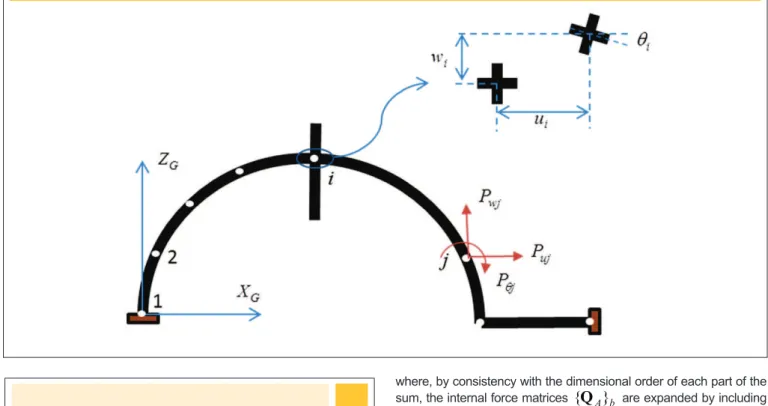
Consider a plain frame composed by straight and circular
ele-ments, as indicated in igure 1. According to a global reference
system XGZG, generalised displacements of a frame node i are
represented by:
u
i,
w
i,
θ
i and external forces on the node j are:PujPwjPƟj. The vector of external nodal forces of a structure with n nodes is indicated as:
(1)
where, by consistency with the dimensional order of each part of the sum, the internal force matrices
{Q
A}
b are expanded by includingzeros on degrees of freedom not correspondent to the element nodes:
(4)
0,
0,
,...,
,
,
0,
0,
0,
,...,
,
,
0,
0,
0,
,...)
0(
}
{
1 nó nó 1 nó nó
1
nó + +
=
j j
j wj uj i i
i wi ui t
b
A
Q
Q
Q
qQ
Q
Q
qQ
For each element is introduced a local reference system xbzb, as
illus-trated in igure 2. In straight elements the local origin coincides with
node i and the xb axis aligns with the chord i–j. The angle between the
(2)
)
,
,
,
,
,
(
}
{
t ui wi i uj wj jb
=
Q
Q
Q
qQ
Q
Q
qQ
It follows that the quasi-static equilibrium equations may be written as:
(3)
Figure 1 – External forces and generalised displacements according to the global reference system
where the expanded kinematic transformation matrix t b A
]
[B
is built in a similar way as indicated in equation (4).3. Kinematic of structures including
straight and circular elements
The nodal generalised displacement vectors of a frame and the analogous vector of an element b between nodes i and j are, re-spectively:
(8)
)
,
,
,...
,
,
,
(
}
{
U
t=
u
1w
1q
1u
2w
nq
n{
q
}
bt=
(
u
i,
w
i,
q
i,
u
j,
w
j,
q
j)
At the element level an additional kinematic variable is deined, which is called generalised deformation matrix
{ε}
b , being conju-gated with generalised stresses by means of the mechanical po-tencyW
b:(9)
bt b b t b b
W
=
{
ε
}
{
σ
}
=
{
q
}
{
Q
}
On the other hand, the generalised deformations may be calcu-lated through nodal generalised displacements of the element. Actually, combining equations (6-9) the following relation can be obtained:
(10)
(
{
ε
}
tb-
{
q
}
tb[
B
]
bt)
{
σ
}
b=
0
"
{
σ
}
bi.e.
{
ε
}
b=
[
B
]
b{
q
}
bThe deformation rates of the element also may be expressed in
local xb and global XG axes is represented by ab. Naturally the angle ab
and the length Lb may be calculated by means of the nodes i and j ac-cording to the global system. In case of circular elements the origin of
the system is placed in the centre of arch, the axis zb passes thru node i
and βb is the angle between the global ZG and local axes zb. The element
forms a circle arch cb. The angles bb and cb may also be calculated by
means of the nodes and element radius, as shown in appendix 1.
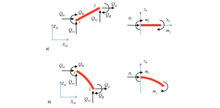
Using the same approach of [19] to a nonlinear elastic frame analysis,
it is deined a second set of static variables coupled up to local refer
-ence: the generalised stress vector of the element (see igure 3):
(5)
)
(
i j it
b
=
m
,m
,n
}
{
σ
On the generalised stress vector,
m
i andm
j are the bending moments on sections i and j, respectively, andn
i is the axial force (positive compression) in i. The vectors of internal forces and stress are related by means of the following equation of static equilibrium:(6)
where
[
B
]
b is called kinematic transformation matrix of the el -ement b. The determination of the matrix[
B
]
b to straight andcurved elements is indicated in the appendix 2.
The matrix of external forces also may be related to generalised
stresses combining equations (3,6):
(7)
terms of the nodal displacement rates of the frame, using the ex
-panded transformations matrix:
(11)
}
{
]
[
}
{
ε
B
U
b A b
=
In case of small displacements, the transformation matrices related to the initial
[B
o]
b and deformed[B
]
b conigurations are practi -cally the same [19]:(12)
bo
b
[
]
]
[
B
@
B
Then the kinematic and static equilibrium equations may be writ-ten as:
(13)
a
(13)
b
4. Hypothesis of strain equivalence
and lumped dissipation
On the classical theory of continuum damage (see e.g. [1]) the deg-radation process of mechanical properties of the solid is represented by means of a variable called continuum damage ω which can take values between zero and one. The continuum damage is introduced in elastic constitutive law using the effective stress concept (that oc-curs on the undamaged part with defects) and the strain equivalence hypothesis (the undamaged part submitted to effective stress pres-ents same strain that the degraded part on nominal stress):
(14)
being σ the Cauchy stress, or nominal stress in case of small strains,
σ
the effective stress, E the Young’s Modulus, ε the total strain and εp the portion of plastic strain.The elastic constitutive relation (14) may be written also in terms of
lexibility [9]. This alternative implies the following relations:
(15)
s
w
e
e
E
p)
1
(
1
-=
-
Þ
e
=
e
e+
e
d+
e
ps
e
E
e
=
1
s
w
w
e
)
1
(
-=
E
dThe speciic strain can be decomposed in three parts: an elastic
term calculated by Hooke’s law, a plastic and damage terms, which arises from micro-defects accumulation on material. This last term
of strain is null if there is no damage and tends to an ininite value
when the damage tends to one. From equations (15) also provide
the interpretation that the material has an initial elastic lexibility
E
1
and an additional lexibility due to material deterioration ex -pressed by:ω
E
(
1
−
ω
)
. Naturally, the additional lexibility does not exist when the material presents no damage and tends to ini -nite when the damage tends to one.To take into account in a simpliied way the inelastic effects of plas -ticity and damage on frame problems, it is assumed the hypothesis of lumped dissipation. Such hypothesis assumes that all inelastic effects are concentrated in plastic hinges (with zero-length) with damage. Therefore, it is supposed that a frame element combines an elastic component and two inelastic hinges localised at its
edg-es (see igure 4).
The application of the strain equivalence hypothesis in this context leads to the following expression:
(16)
b d b p b eb
{
}
{
}
{
}
}
{
ε
=
ε
+
ε
+
ε
The matrix
{ε
e}
b contains the elastic generalised strain compo-nents of the element. These strains are expressed in terms of the generalised stresses, using the elastic lexibility matrix
[
F
o]
:(17)
b o b
e
}
[
]{
}
{
ε
=
F
σ
The expressions of
[
F
o]
are presented in appendix 3.5. Internal variables: plastic rotations
and damage on hinges
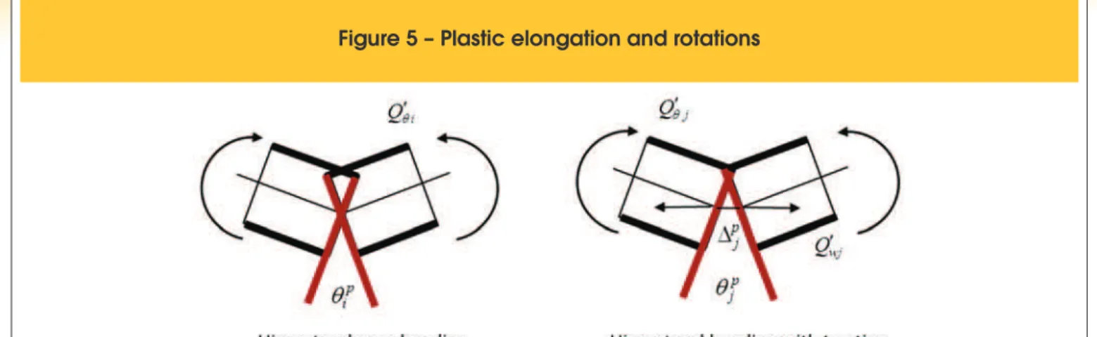
The hinges may have plastic rotations and elongations as
indi-cated in igure 5. Therefore, the plastic dissipated energy of the
element is [16]:
(18)
p j uj p j j p i ui p i ip
Q
Q
Q
Q
W
=
¢
q
-
¢
D
+
¢
q
+
¢
D
qq
where are the bending moments and axial forces on i and j element edges, as indicated in appendix 2.
On the other hand, be the components of
generalised plastic strains matrix, then the plastic dissipation may
also be written as:
(19)
p j uj p j j p i ui p i i p i p j j p i i t pp
m
m
n
Q
Q
Q
Q
W
=
=
f
+
f
+
d
=
¢
q
-
¢
D
+
¢
q
+
¢
D
q q
}
{
}
{
ε
σ
In case of a straight element:
Q
θ′
i=
m
i,Q
θ′
j=
m
j, and iuj
n
Q
′
=
−
. Thus, from relation (19) some physical interpretationto components of plastic strains matrix arise:
(20)
pi p i
q
f =
pj p j
q
f =
(
p)
j p i p
=
-
D
+
D
d
i.e. the terms
φ
ip andφ
jp are plastic rotations on hinges i and j, andδ
p is the permanent elongation of the element.In case of a circular element we have:
Q
θ′
i=
m
i,Q
θ′
j=
m
j,, (see equation (2) of appendix 3), ergo:
(21)
R
p i p i pi
=q
-
D
f
R
p j p j pj
=q
-
D
f
(
p)
j p i p
=
-
D
+
D
d
Thereby
φ
ip andφ
jp are not exactly plastic rotations. However, to arches with large radius and small permanent elongations this difference is negligible, being possible to admit thatφ
ip andφ
jp are plastic rotations.Now, a second set of internal variables on hinges is introduced, gathered in the following damage vector:
{
}
(
i,
j)
t b
=
d
d
D
.These variables take values between zero and one, as in the case of continuum damage, however in the present model those variables measure densities of macro-cracking on concrete (see
igure 6).
Thereby, according to the strain equivalence hypothesis the strains
due to damage on hinges may be expressed as:
(22)
b b
d
}
[
(
)]{
}
{
ε
=
C
D
σ
ú
ú
ú
ú
ú
ú
ú
ú
û
ù
ê
ê
ê
ê
ê
ê
ê
ê
ë
é
-=
0
0
0
0
)
1(
0
0
0
)
1(
)]
(
[
2200 11 j j i i
d
F
d
d
F
d
D
C
where are coeficients of the elastic lexibility matrix of element. The equations (16, 17 and 22) allow writing the elasticity law of an element as:
(23)
The previous relation also evidences that the flexibility ma
-trix of the element may be decomposed in an initial elastic
term and an additional term due to damage. When the
dam-age is zero the additional part of flexibility is null, since when the damage approaches the unit value the additional flexibility
tends to infinity.
5.1 Generalised Grifith criterion for the calculation
of damage in an inelastic hinge
On the classic Fracture Mechanics the criterion of crack propaga-tion in a continuous environment is obtained from a balance of energy and introducing the energy release rate concept. An analo-gous approach may be conducted in the case of a frame element [4]. The complementary strain energy Wb of the element is:
(2
4)
b t b b p t b bW
{
}
[
(
)]{
}
2
1
}
{
}
{
2
1
σ
ε
-
ε
=
σ
F
D
σ
=
Then, the energy release rate of inelastic hinges is given by:
(25)
In this case, the energy release rate acts as a crack inductor
ther-modynamic ‘moment’. Hence, the Grifith criterion establishes that
the propagation of damage in a hinge i is possible only if the in-ductor moment equate crack resistance R(di). Once such critical
condition is veriied, the damage evolution, for each element, is
governed by the following conditions:
(26)
where
∆
d
i and∆
d
j represent the damage increments on hing-es i and j, respectively.A relation to the crack resistance was proposed in [4] based on an
experimental evaluation as:
(27)
The element has an initial crack resistance R0 and a logarithmic hardening term proportional to parameter q. This last parameter
accounts for the reinforcement effect in concrete, which
ham-pers the crack propagation. The Grifith propagation condition,
)
(
i iR
d
G
=
, describes, essentially, the relation between the bending moment on the hinge and the damage level, as illustratedin igure 7.
The parameters R0 and q may be identiied such that the
damage-bending moment curve its through points corresponding to the
cracking moment of the cross-section Mcr and to the ultimate mo-ment Mu [4]. This alternative allows dismissing experimental analy
-sis for purposes of parametric identiication, involving, therefore,
only parameters and classical concepts of conventional reinforced concrete theory.
5.2 Evolution law of plastic rotation
on a damaged hinge
The last set of equations of the simpliied model is the evolution
law of plastic strains. In the classic plasticity theory this relation
is obtained from a yield function. In the simpliied model two func -tions are introduced:
f
i≤
0
andf
j≤
0
, in correspondence toeach inelastic hinge of the element. Being the hardening effect described by a kinematic model the aforementioned functions are given by:
(2
8)
0;
0
b p b p
i i i y j j j y
f m c
=
-
f
-
M
£
f
=
m c
-
f
-
M
£
being
M
y the effective plastic yield moment and c the effective plastic stiffness. Both parameters also may be calculated using the reinforced concrete theory [4].Neglecting plastic elongations, the evolution laws of plastic ro-tations result from a complementary condition with the yield functions:
(29)
Figure 6 – Lumped damage variables
To take into account also the effects of cracking moment, the yield
functions may be modiied using, again, the strain equivalence hy -pothesis in stiffness terms. Therefore, the effective moments b
i
m and b
b
m at hinges are deined as follows:
(30)
Therewith, the yield functions with linear kinematic hardening can be rewritten as:
(31)
6. Numerical implementation
Consider, again, the equilibrium equation (3) conveniently rewritten:
(3
2)
Equation (32) establishes that the solution is only obtained when the residual force vector
{
Res
}
, deined as the difference betweenthe internal and external forces, is null.
A inite element programme is here composed of a set of routines
that process the user input, generate the structure calculation pro-cess step-by-step and provide the analysis results in tabulated or graphical form. At each calculation step, the programme solves
numerically the problem deined by the matrix equation (32) ac
-counting for the boundary conditions. These conditions are deined
by known displacement values in regions where the forces are un-known and vice-versa.
The inite element is fundamentally inserted in the routine that cal -culates the internal forces {Q}b from displacements. The
compu-tational procedure that expands the matrices of internal forces and combines them in the matrix of residual forces is the well-known
assemblage algorithm.
The proposed frame element is then deined by the kinematic
equation (13a), which allows the strain calculation from displace-ments, by the elastic (23), damage (26) and plasticity (28) laws, which provide the generalised stresses and internal variables from
strains and, inally, by the equilibrium equation (13b), which returns
the internal forces from stresses.
The system of global equilibrium equations of the structure (31) is, in general, nonlinear. Therefore such system must be solved by linearization of the problem with some iterative method to cor-rect the solution estimative, being the Newton’s method or any of its variants usually employed. In this case, due to the
lineariza-tion, it is also necessary the calculation of tangent stiffness matrix,
or jacobian, of internal forces:
b ∂ ∂ U U Q( )
.
Notice that the constitutive model, represented by the set of
equa-tions (23,26,28) is also nonlinear. Therefore, it is necessary the use of Newton’s method combined with a predictor and corrector strategy in local character. It is noteworthy that an especial charac-teristic of this type of local problem is that the convergence
condi-tions vary signiicantly with the damage i.e. as higher the damage
value to be calculated as lower is the increment size. Furthermore, loading increases are usually followed by damage concentration on few hinges. That is why the classical procedure, which involves calculations of both global and local equilibrium problems is not
eficient. In this case, it is preferable to use different steps of calcu -lation on each element [20]. Figure 8 shows a possible algorithm based on this idea.
7. Examples
7.1 Precast tunnel segment
In [21] experimental tests on precast segments that compose
the Brennero Base Tunnel, which connects Italy to Austria are
described. The tunnel is composed by six segments, presenting 19m of circumferential length and 6 m of external diameter. The
considered segment presents dimensions of thickness, length and width equal to 200 mm, 3640 mm and 1500 mm, respectively
(see igure 9).
The precast segment analysed in [21] presents concrete with
char-acteristic compression strength of 50 MPa and lexural reinforce
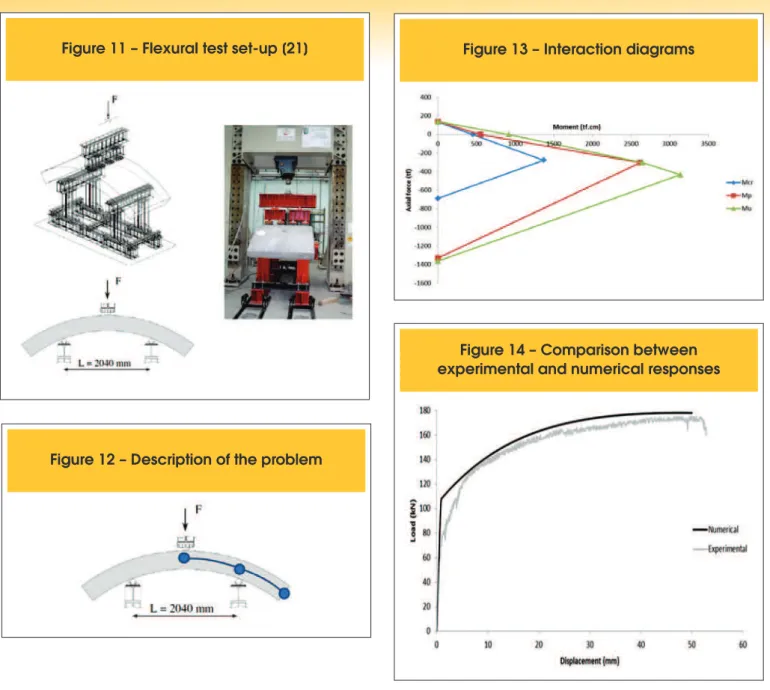
-ment composed by rebars with 8 mm of diameter (see igure 10). Attempting to assess the response of the proposed model, the lex
-ural test on the segment was hereby chosen (igure 11), among the
described tests in [21].
Thus, taking advantage of symmetry of the problem, the simulation
was realised using only two arch inite elements (igure 12).
In possession of the adopted material properties and of the cross-section characteristics [21], by using the classical theory of
re-inforced concrete interaction diagrams between axial force and bending moment in the section were obtained (igure 13). As the axial force along longitudinal direction of the tunnel structure may be neglected, from the interaction diagrams were identiied values
of 451 tf.cm, 550 tf.cm and 916 tf.cm to the cracking, plastic and ultimate moments, respectively.
The comparison between the numerical and experimental re -sponses, in terms of load versus displacement of the point of load
application, is presented in igure 14.
It is observed that the numerical solution is well itted to the experi -mental response.
7.2 Prestressed and precast concrete
segmental lining
To build a tunnel (igure 15a) in the city of Osaka [22], Japan, pre
-cast concrete segmental lining was used (igure 15b).
To analyse the structural behaviour were realised lexural tests (igure 16) on specimens composed by two precast segments, applying prestress force of 29.4 kN per strand, [22]. In experi -mental set the semi-circumference formed by the abovemen-tioned assemblage was simply supported at the base, being the load applied in two points equidistant 450 mm of the central
sec-tion of (see igure 17).
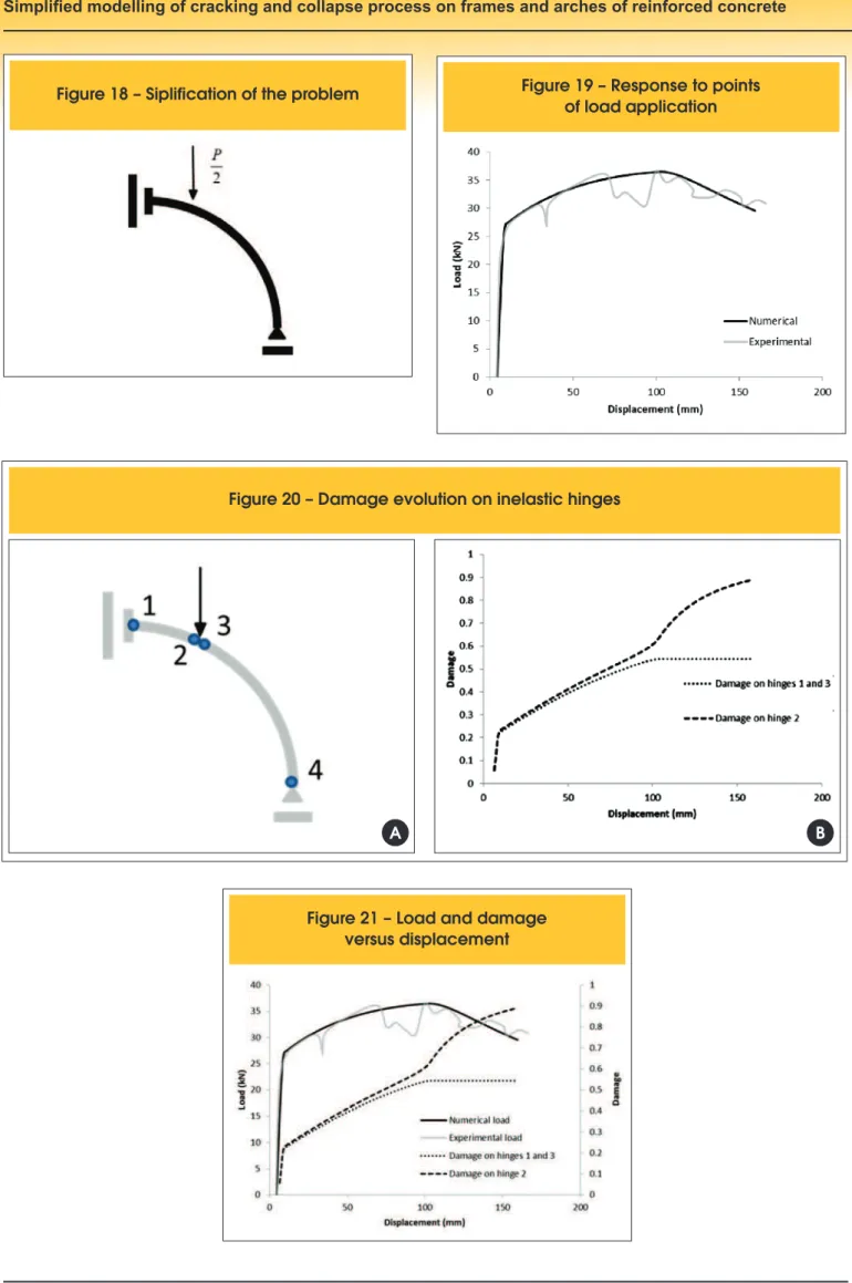
The numerical simulation was performed taken proit of the sym
-metry presented by the problem (igure 18).
The obtained response with the proposed model (igure 19) was compared to the average experimental response, given in [22].
It is noteworthy that the model parameters for this problem were
experimentally measured, also considering the applied prestress.
average experimental response, including its descendent stretch.
This stretch occurs due to localisation phenomena of the inelastic effects in the region under the applied load. In the proposed model, this localised effect was captured on one of the inelastic hinges
(igure 20a), to where the damage evolutions (igure 20b) and plas -tic rotations clearly converge, reaching concerning values related to the structural integrity.
Figure 21 overlaps the graphics presented in igures 19 and 20b,
for a better analysis.
In figure 21 it is observed that the damage on hinges evolves quickly in the first stage of loading, being concrete cracking the only inelastic effect present. As soon as the reinforcement initi-ates its yielding process the damage growth turns less
accel-erated. At the instant that the structure reaches the maximum value of load resistance measured experimentally (see [22]),
the damage on hinge ‘2’ presents itself with intensity about
0.6, which is considered excessive to reinforced concrete
structures, [23]. From this point on, the structure continues to deform in a process of controlled displacement. The damage responses, and also the plastic strain, keep constant at hinges ‘1’ and ‘3’. However, the damage (and also the plastic strain) continues to evolve in hinge ‘2’. Thus, it is possible to affirm that beyond this point of the analysis the localisation phenom-enon of inelastic processes occurs. It is noteworthy that the hinge ‘4’ has not activated its inelastic processes throughout the analysis.
8. Conclusions
The formulation proposed in this paper aims to describe with good precision the behaviour of framed structures in presence of inelas-tic effects concentration. To assess the numerical response of the
model two experimental tests of structures composed by circular arches were considered. In the irst example, beyond the accuracy
aspects, the robustness of the proposed formulation was put into test in a certain sense, since the parameters were obtained by using conventional theory of reinforced concrete. In the second
example, it was observed that the formulation is also capable to
reproduce, in a satisfactorily way, the localisation phenomenona of inelastic processes. Thus, it became clear that the proposed model is able to reproduce, consistently, nonlinear behaviour of real rein-forced concrete structures.
9. References
[01] Lemaitre, J., Chaboche, J. L. Mechanics of Solids Materials,
Dunod, Paris, 1988.
[02] Bazant, Z. P., Jirasek, M. Nonlocal Integral Formulations of
Plasticity and Damage: Survey of Progress. Journal of Engi -neering Mechanics, v.128, n.11, 2002; p.1119–1149.
[03] Peerlings, R. H. J., de Borst, R., Brekelmans, W. A. M., de Vree, J. H. P. Gradient enhanced damage for quasi-brittle materials. International Journal for Numerical Methods in En -gineering, v.39, n.19, 1996; p.3391–3403.
[04] A. Cipollina, A. López-Inojosa, J. Flórez-López, A simpli
-ied damage mechanics approach to nonlinear analysis of
frames. Computers and Structures; v.54, n.6, 1995; p.1113-1126.
[05] M.E. Perdomo, A. Ramirez, J. Flórez-López, Simulation of damage in RC frames with variable axial forces. Earthquake
Engineering and Structural Dynamics, v.28, n.3, 1999; p.311-328.
[06] Álvares, M. S. Contribuição ao estudo e emprego de modelos simpliicados de dano e plasticidade para a análise de estruturas de barras em concreto armado, São Carlos, 1999, Tese (doutorado) – Escola de Engenharia de São Carlos, Universidade de São Paulo, 123p.
[07] Marante, M. E., Flórez López, J. Three dimensional analysis
of reinforced concrete frames based on Lumped Damage
Figure 9 – Tunnel segment geometry [21]
Fi
gure 12 – Description of the problem
Figure 13 – Interaction diagrams
Figure 1
4 – Comparison between
experimental and numerical responses
Figure 15 – Built tunnel in Osaka (a) using prestressed and precast concrete segments (b), [22]
A
B
Figure 16 – Flexural test set up (photo) [22]
Figure 1
7 – Flexural test set up [22]
Mechanics, International Journal of Solids and Structures,
v.40, n.19, 2003; p.5109‐5123.
[08] Alva, G. M. S. Estudo teórico-experimental do comporta
-mento de nós de portico de concreto armado submetidos a
ações cíclicas, São Carlos, 2004, Tese (doutorado) – Escola de Engenharia de São Carlos, Universidade de São Paulo, 218p.
[09] Perdomo, M. E., Picón, R., Marante, M. E., Hild, F., Roux, S., Flórez-López, J. Experimental analysis and mathematical modeling of fracture in RC elements with any aspect ratio. Engineering Structures, n.46, 2013; p.407–416.
[10] Araújo, F. A., Proença, S. P. B. Application of a lumped dis-sipation model to reinforced concrete structures with the consideration of residual strains and cycles of hysteresis,
Journal of Mechanics of Materials and Structures, v.3, n.5,
2008; p.1011-1031.
[11] Flórez-López J. Simpliied model of unilateral damage for RC frames. Journal of Structural Engineering, v.121, n.12,
1995; p.1765–1772.
[12] Alva, G. M. S., El Debs, A. L. H. C., Application of lumped dissipation model in nonlinear analysis of reinforced con-crete structures. Engineering Structures, v.32, n.4, 2010; p.974-981.
[13] Febres R, Inglessis P, Flórez-López J. Modeling of local
buckling in tubular steel frames subjected to cyclic loading. Computers and Structures,v.81, 2003; p.2237–47.
[14] Palaninathan, R., Chandrasekharan, P. S. Curved beam
element stiffness matrix formulation. Computers and Struc -tures, v.21, 1985; p.663-669.
[15] Marquist, J. P., Wang, T. M. Stiffness matrix of parabolic
beam element. Computers and Structures, v.31, 1989, p.863-870.
[16] Flórez-López, J., Proença, S. P. B. A curvilinear frame ele -ment with plastic hinges. In: IV International Symposium on
Solid Mechanics, Porto Alegre, 2013.
[17] Tang, X. S., Zhang, J. R., Li, C. X., Xu, F. H., Pan, J. Damage
analysis and numerical simulation for failure process of a re-inforced concrete arch structure. Computers and Structures, v.83, 2005; p.2609-2631.
[18] Shi, Z. Crack analysis in structural concrete, theory and
ap-plications. Elsevier Oxford, 2009.
[19] Powell, H. G. Theory for nonlinear elastic structures. Journal
of the Structural Division (ASCE), ST12, 1969; p.2687-2701. [20] Avon, Z., Denis, T. Un algoritmo para mejorar la
Figure 18 – Siplification of the problem
of load application
Figure 20 – Damage evolution on inelastic hinges
A
B
!"#$%&'()*+,-,.-- ,/ ,# &
2002, Dissertação (mestrado) – Universidad de Los Andes. [21] Caratelli, A., Meda, A., Rinaldi, Z., Romualdi, P. Structural
behaviour of precast tunnel segments in iber reinforced con -crete. Tunnelling Underground and Space Technology, v.26, 2011; p.284-291.
[22] Nishikawa, K. Development of a prestressed and precast
concrete segmental lining. Tunnelling Underground and Space Technology, v.18, 2003; p.243-251.
[23] Alarcón, E., Recuerdo, A., López, C., Gutierrez, J. P., de Di
-ego, A., Picón, R., Flórez-López, J. A reparability index for
APPENDIX 1
Let
(
X
c,
Z
c)
,(
X
i,
Z
i)
and(
X
j,
Z
j)
coordinates on the global axes of curvature of nodes i and j of a circular arch element. Worth then the relations:(1)
Eliminating the value of radius in these expressions, it can isolate the value of
X
c as a function of the other values:(
2)
The centre coordinate
Z
c may be obtained by means of the resolution of the following equation:0
2
+
+
=
c
Z
b
Z
a
c c;
where:(3)
From equation (3) are obtained two different solutions to the centre coordinate. Particularly, if the nodes i and j are chosen clockwise and α is lower than π, then is a vector in the positive direction of the global axis
Y
G. This condition may be used to identify automati-cally the correct solution:(
4)
Finally, the angles bb and cb are deined as:
APPENDIX 2
Consider again the circular element, now described in local coordinates (see igure 1). It is considered, next, a static variable deined by
the vector of internal forces, however associated to the global coordinates: .
(1)
In matrix form:
(
2)
The vectors of internal forces referenced by global coordinates,
{Q
}
b, and local coordinates,{Q′
}
b, are related by means of the matrixof conventional geometric transformation
[T
]
b:(
3)
where
[T
]
b is deined as:(4)
Therefore:
(5)
The matrix of kinematic transformation to a straight element is obtained by means of an analogue procedure:
APPENDIX 3
Consider the circular element. Let
M
(
θ
)
,V
(
θ
)
, andN
(
θ
)
the bending moment, shear force and axial force in a cross-section identi-ied by an angle θ from the edge i (see igure 1).
The equilibrium relations are, now, written as:
(1)
The system of equations (1) associated to the expression of internal force
Q′
wi obtained in appendix 2 allows express the axial force,shear force and bending moment in terms of the generalised stresses:
(2)
The elastic strain energy in the element may then be written as:
(3)
where the terms EIb, GAb and AEb have the usual meaning. The coeficients of the elastic lexibility matrix may be obtained from the Cas
-tigliano’s theorem. Particularly, if the shear deformations are neglected those coeficients are:
(4)
The elastic lexibility matrix to a straight element is obtained by an analogue procedure, resulting:


![Figure 9 – Tunnel segment geometry [21]](https://thumb-eu.123doks.com/thumbv2/123dok_br/18860678.417872/10.892.58.834.55.777/figure-tunnel-segment-geometry.webp)
![Figure 17 – Flexural test set up [22]](https://thumb-eu.123doks.com/thumbv2/123dok_br/18860678.417872/12.892.63.830.581.1115/figure-flexural-test-set-up.webp)