*e-mail: [email protected]
1. Introduction
Severe Plastic Deformation (SPD) techniques have become the prominent processing technologies1-28 for the production of bulk ultra ine-grained materials with special physical and mechanical properties28-32, by material pressure forming methods25,26. The mechanics of metal low during Equal Channel Angular Extrusion (ECAE) or Equal Channel Angular Pressing (ECAP) through the 2θ-dies of simple Segal geometry attracts a lot of research contributions from different ields of theoretical1-28, experimental28-32 and industrial8,25,33 science. ECAE assumes one or several extrusion passes of a lubricated billet in a 2θ-die of Segal geometry with two intersecting channels of equal cross-section in Figures 1-2. Materials’ processing by ECAE results in the accumulation of large shear strains and grain reinement. The obtained materials show the combination of a very high strength and ductility.
Therefore, studies of ECAE mechanics through the 2θ-dies of simple Segal geometry form an important branch of modern applied plasticity science.
There are several computational approaches to the phenomenological description of metal low during ECAE. Many contributions have been focused on the introduction of slip line ields25,26, Upper Bound Method (UBM) with continuous trial velocity ields1-6,8-10,12-15,24,27, kinematically admissible analytical approaches11,28, FEM computational techniques2,8,9,11,17,18,23, Navier-Stokes equations16,20,21 etc.
Segal25,26 has grounded his analytic approach to ECAE metal low with the introduction of slip line ields. Tóth et al.28 have proposed a novel analytic approach to ECAE copper
low with the introduction of a low line model. Milind & Date11 have applied generalized analytical kinematic models for ECAE strain estimation.
The Upper Bound Method (UBM)-based analytical solutions of ECAE problems for metal workpiece low through ECAE dies have been derived in works of Abrinia & Mirnia1, Alkorta & Sevillano2, Altan et al.3, Eivani & Karimi Taheri4,5, Faraji et al.6, Laptev et al.7, Luri et al.8, Luri & Luis9, Medeiros et al.10, Narooei & Karimi Taheri12-14, Paydar et al.15, Perig & Laptev19, Perig22, Reihanian et al.24, Talebanpour & Ebrahimi27 and others. Altan et al.3 have addressed the Upper Bound Method (UBM) with continuous trial velocity ields for description of metal ECAE motion through the Segal die. The main computational approach3 has been based on the use of a cylindrical coordinate system with the center of a symmetrical metal deformation zone, deinition of a kinematically admissible velocity ield for metal low, evaluation of the only non-zero strain rate ield component d(εrθ)/dt, formulation of an equation for dissipated power balance and further minimization of the derived expression for dissipated plastic power by optimization parameter differentiation.
The numerical inite difference simulation of polymer ECAE low through angular dies with different geometries has been developed in the works of Perig et al.16, Perig & Golodenko20,21. Perig et al.16 have applied the Navier-Stokes equations in the curl transfer form for the numeric inite-difference description of viscous material low through the following dies: (I) ECAE die with channel intersection angle 2θ=90°[16], (II) S-shaped multiple angle die with movable inlet wall20, and (III) ECAE die with channel intersection angle 2θ=90° and
Two-parameter Rigid Block Approach to Upper Bound Analysis of
Equal Channel Angular Extrusion Through a Segal 2θ-die
Alexander Periga*
aDepartment of Industrial Automation, Donbass State Engineering Academy, Shkadinova Str., 72, Kramatorsk, Ukraine, 84313
Received: April 16, 2015; Revised: May 31, 2015
This article deals with a phenomenological description of experimentally determined complex geometric shape of material dead zone during Equal Channel Angular Extrusion (ECAE) through a Segal 2θ-die with a channel intersection angle of 2θ>0° and 2θ<180°. Taking into account the complex dead zone geometry in a 2θ-die, a two-parameter Rigid Block Method (RBM) approach to a two-parameter Upper Bound Method (UBM) has been introduced with Discontinuous Velocity Field (DVF) for planar low of plastic incompressible continua. The two-parameter UBM has allowed us to derive the numerical estimations for such energy-power parameters of ECAE as punching pressure and accumulated plastic strain for 2θ-dies. The obtained computational data have been compared with the one-parameter analytic UBM solution. Good agreement between the two computational results has been found.
with parallel slants in the channel intersection zone, where the slant width is equal to the inlet and outlet channel widths21.
There are inite element method (FEM)-based approaches to metal low during SPD2,8,9,11,217,18,23. The FEM-based numerical solutions of ECAE problems for metal workpiece low have been derived in works of Alkorta & Sevillano2, Luri et al.8, Luri & Luis9, Milind & Date11, Perig et al.17,18,23 and others.
The quantitative description of material structure fragmentation during ECAE requires the introduction of experimental techniques28-32. Berta et al.29 outline comparable experimental ECAE data on the structure of the treated metal blanks at various channel angles 2θ=90° and 2θ=120°[29].
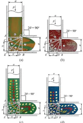
It is necessary to note that many analytical computational approaches1-6,8-10,12-15,24,27 initially determine the shape of the dead metal zone CED in an angular Segal 2θ-die (Figures 3-6). Simple physical simulation experiments for analysis of ECAE low through a non-rectangular Segal 2θ-die in Figures 3-6 show the complex structure of the dead metal zone CEDF (Figures 3-6), which has not been adequately addressed in previous known publications1-10,12-15,19,22,24,27,28.
Moreover, the two-parameter rigid block approach to the two-parameter UBM of metal low during ECAE with trial Discontinuous Velocity Field (DVF) introduction and accounting for the complex geometry of dead zone CEDF (Figures 3-6) for metal low through a Segal 2θ-die has not been addressed in proper way in previous known publications1-10,12-15,19,22,24,27.
All previous research1-10,12-15,19,22,24,27 has not fully addressed the complex geometry of the dead metal zone
Figure 1. The principal scheme of ECAE billet processing through the 2θ-die.
Figure 2. The principal scheme of ECAE billet processing through the 2θ-die model with 2θ=90° (a) and 2θ=105° (b).
Figure 3. Physical model of the shape of the material dead zone
CEDF during ECAE through a Segal 2θ-die with channel intersection angle 2θ=75° after three ECAE passes via deformation route C.
Figure 4. Physical model of the shape of material dead zone CEDF
during ECAE through a Segal 2θ-die with channel intersection angle 2θ=90°.
Figure 5. Physical models of the shape of material dead zone CEDF
CEDF (Figures 3-6) nor the inluence of complex dead zone geometry CEDF (Figures 3-6) on the character of metal low during workpiece ECAE through a Segal 2θ-die applying a two-parameter UBM in the form of a two-parameter RBM with trial DVF. This insuficient analysis of energy-power parameters during ECAE with an introduction of the two-parameter UBM with DVF was the stimulus, which resulted in the research reported in the present article. This article is the irst application of a two-parameter rigid block approach to a two-parameter UBM with DVF to workpiece 2D plastic low through a Segal-geometry 2θ-die.
The aim of the present research is the phenomenological Upper Bound Method-based description of metal workpiece plastic ECAE low through a 2θ angular die of Segal geometry during ECAE accounting for the complex geometry of dead zone CEDF.
The subject of the present research is the plastic low of metal workpiece model through the ECAE process with 2θ angular die of Segal geometry.
The object of the present research is the general deinition of the character of the plastic low of a metal workpiece model through a 2θ angular die of Segal geometry with respect to the complex dead zone geometry and ECAE process parameters.
The experimental novelty of the present article is the introduction of initial circular gridlines to study workpiece low through the ECAE process with 2θ angular dies of Segal geometry, shown in Perig’s derived experimental approaches in Figures 3-6.
The prime novelty of the present research is the irst time application of the two-parameter rigid block method to the estimation of punching pressure and plastic shear during metal workpiece ECAE through 2θ-die of Segal geometry, accounting for the complex geometry of dead zone CEDF in Figures 3-6.
2. Complex Dead Zone Geometry Influence
on Material Flow During ECAE
In order to verify the complex character of dead metal zone CEDF (Figures 3-6) we will address to simple physical simulation experiments with plasticine (Figures 3-6) workpiece models low through the physical models of Segal 2θ-dies with
channel angles 2θ=75° (Figure 3), 2θ=90° (Figures 2a, 4-5), and 2θ=105° (Figures 2b, 6).
The irst experimental approach to analyze the dead metal zone shape CEDF (Figures 3-6) has been grounded on the introduction of layered models (Figure 5a) for workpiece model low through a Segal-geometry die. However it has been found that layered models deine only a general shape of dead zone CED near the corner point E without
clariication of dead zone CED external contours in the inlet AOE and outlet BOE die channels in Figure 5a. So a second type of approach has been applied using a physical marker experimental method (Figures 4 and 5b), which provided us with general idea about external shape of dead zone CEDF.
It has been found that dead metal zone CEDF (Figures 3-6) in the workpiece volume has the shape near to the trial computational shape in Figure 7a. Additional physical simulation experiments required addressing to the physical models with the initial circular gridlines (Figures 3 and 5c-d). In Figures 3-6 the physical workpiece models’ low goes within inlet channel AOC from the punch level to deformation zone entrance line AO; then towards bisector line EO and then in the outlet channel BOE from EO to BO. Using both solid markers (Figures 4, 5b), layered models (Figure 5a), and initial circular gridlines (Figures 3 and 5c-d) it has been found experimentally that in the 2θ-die external corner E the dead zone CEDF of plastic material low appears and has a
quite complex geometrical shape with additional “bottleneck”
EF (Figures 3-6), i.e. with formation of additional break point F along bisecting line EO in the area of the cross point for two intersecting conditional lines EO and AB (Figures 3-6).
3. Two-Parameter Upper Bound Analysis for
a Segal 2θ-Die
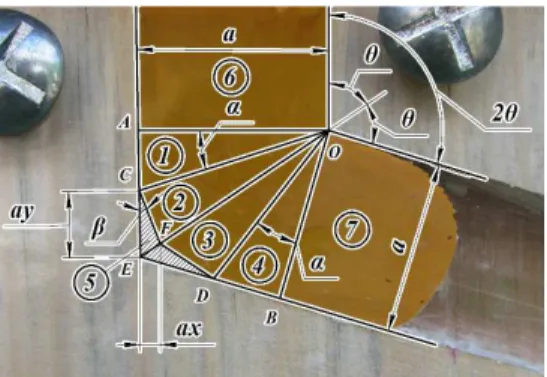
In accordance with observable results of physical simulation-based experiments in Figures 3-6 we assume the formation of a complex shape dead zone CEDF with the appearance of the additional straight arch EF, which limits
the “spreading” of the metal dead zone to the CDF area in Figures 3-7. So the appearance of a symmetrical complex shape dead metal zone CEDF has been shown in Figures 3-7.
The upper bound theorem equation according to the works34,35 has the following form:
(
)
Johnson- Kudo ( k Johnson- Kudo)Johnson- Kudo
= ∆ ′ + ∆′
∑ij ij ∑ k k
dE
k l u f l u
dt (1)
where
(dE/dt)Johnson-Kudo is deined in Johnson & Kudo34 and Kudo35 as “the total rate of energy dissipation in the system per unit thickness in the direction normal to the plane of low”; multiplier (k)Johnson-Kudo is deined in Johnson & Kudo34 and Kudo35 as “the shear stress”;
(lIJ)Johnson-Kudo and (Δu/
IJ)Johnson-Kudo are deined in Johnson & Kudo34 and Kudo35 as “the length of a straight boundary and the rate of relative slip between triangles “i” and “j”
respectively”;
(fK)Johnson-Kudo, (lK)Johnson-Kudo and (Δu/
K)Johnson-Kudo with subscript k are deined in Johnson & Kudo34 and Kudo35 as “the frictional resistance, the length of contact and the rate of relative slip between triangle k and the contacting tool surface”34,35).
Figure 6. Physical model of the shape of material dead zone CEDF
It has been shown that the dead zone CEDF shape may be only symmetrical one with axis of symmetry EF, because possible asymmetry of dead zone CEDF leads to a violation of workpiece material incompressibility for the rigid blocks division used in Figures 3-6, 7a. The 2D plane model of the metal workpiece during ECAE in 2θ-die has been divided into 7 rigid triangular sections, as shown in Figures 3-6, 7a.
According to the two-parameter UBM (Figures 3-6, 7a, Tables 1-3) a trial velocity ield (Figure 7b, Tables 1-3) has to be introduced.
For the analysis of the ECAE metal low the trial velocity ield for UBM can be continuous, discontinuous or mixed. In the present work the Discontinuous Velocity Field (DVF) for the two-parameter UBM has been used in Figure 7b and in Tables 1-3. Derived experimental data have shown that it’s better to describe the shape of the symmetrical dead zone CEDF in Figures 3-6, 7a and in Tables 1-3 with two independent parameters h=a•x and H=a•y. Here a is the width of inlet AO and outlet BO 2θ-die channels; x is the relative horizontal length of “waist” or bottleneck and y is the relative height of the dead zone in both entrance AOE and outlet BOE channels (Figures 3-6, 7a and Tables 1-3). The appearance of a symmetrical dead metal zone CEDF
in the shape of the twin rigid triangular block numbered
5, which is adjacent to the 2θ-die external angle CED, locates in both inlet AOE and outlet EOB 2θ-die channels (Figures 3-6, 7a and Tables 1-3) and has the height H=a•y and length h=a•x. We also will assume that metal ECAE through a Segal 2θ-die with channel intersection angle 2θ>0° and 2θ<180° occurs with no back-pressure. Additionally we will assume that the constant plastic friction between the workpiece and 2θ-die walls AC and DB is independent of the normal stress σN and is acting only at inlet lAC and outlet lDB lengths (Figures 3-6, 7a and Tables 1-3).
The friction stress τF we will deine according to the Siebel (Tresca) friction law as τF=m•k, where 0.0≤m≤1.0 is the plastic friction factor in the Siebel (Tresca) friction law and the shear strength of the extruded material k=σS/30.5 is the plastic constant, i.e. k is the maximum tangential stress for material with low stress σS. We will calculate the relative punching pressure p/2k (Figures 8a,c;9a,c) at the entrance line AO. Corresponding to the partitioning scheme in Figures 3-6, 7a and in Tables 1-3 a velocity hodograph has been shown in Figure 7b. The extruded workpiece material we will assume as rigid-plastic with no strain-hardening. The plastic friction force has been assumed as independent of sliding velocity.
The balance of external and internal power of plastic deformation has been expressed by the following algebraic equation (Figures 3-9 and Tables 1-3):
[ ] [ ] [ ] [ ] [ ]
(
)
( )
1
1 2 1 2 2 3 2 3 3 4 3 4 2 5 2 5 3 5 3 5
1 3
− − − − − − − − − −
⋅ ⋅ = ⋅
⋅ + ⋅ + ⋅ + ⋅ + ⋅ +
+ ⋅ AC⋅ +DB⋅ p a V k
l V l V l V l V l V
mk l V l V
(2)
where p is an applied ECAE punching pressure through the 2θ-die of Segal geometry (Figures 8a,c;9a,c);
lI-J are the lengths of common boundaries or join interfaces for rigid blocks i and j (Figures 3-6, 7a and Tables 1–3);
l1-2 = l3-4 = CO (Figures 3-6, 7a and Tables 1–3); l2-3 = EO(Figures 3-6, 7a and Tables 1–3);
ax EF
sin
=
θ is the length of additional straight arch EF in
Figures 3-6, 7a;
lAC=lDB are the lengths of friction zones in Figures 3-6, 7a, where AC = a(cotθ-y);
(
)
2AC cot y
sin
CO 1 cot y
θ −
α = =
+ θ − is the sine of angle α or the irst
algebraic equation for angle α determination in Figures 3-7;
Figure 7. Scheme of ECAE 2θ-die of Segal geometry with non-zero friction m≠0 (a, b): a – rigid block two-parameter partitioning scheme;
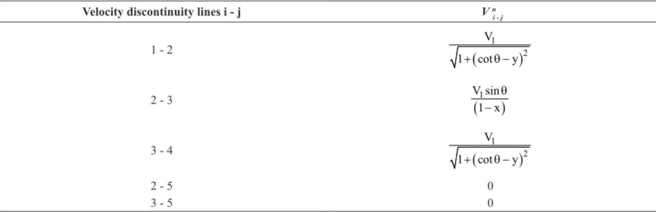
Table 1. The lines of discontinuity and sliding velocities for ECAE 2θ-die with 2θ>0° and 2θ<180° (x=h/a and y=H/a) in Figures 3-7.
Velocity discontinuity lines i - j li - j [Vi - j]
1 - 2
(
)
2
a 1+ cotθ −y
(
)
(
)
2 1
V x 1 cot y
y 1 x
+ θ −
−
2 - 3 a
(
1 x)
sinθ −
(
)
(
(
)
)
1
2V y cos x cos cot sin
y 1 x− ⋅ θ − ⋅ θ⋅ θ + θ
3 - 4
(
)
2
a 1+ cotθ −y
(
)
(
)
2 1
V x 1 cot y
y 1 x
+ θ −
−
2 - 5
(
(
)
)
2 2 2
a y +x 1+ cotθ −2xy cot⋅ θ
(
(
)
)
(
)
2 2 2
1
V y x 1 cot 2xy cot
y 1 x
+ + θ − ⋅ θ
−
3 - 5
(
(
)
)
2 2 2
a y +x 1+ cotθ −2xy cot⋅ θ
(
(
)
)
(
)
2 2 2
1
V y x 1 cot 2xy cot
y 1 x
+ + θ − ⋅ θ
−
Table 2. The lines of discontinuity and sliding velocities for ECAE 2θ-die with 2θ>0° and 2θ<180° (x=h/a and y=H/a) in Figures 3-7.
Velocity discontinuity lines i - j V n
i - j
1 - 2
(
1)
2V
1+ cotθ −y
2 - 3 V sin
(
1)
1 x
θ −
3 - 4
(
)
1 2 V
1+ cotθ −y
2 - 5 0
3 - 5 0
Table 3. The lines of discontinuity and sliding velocities for ECAE die with 2θ=90° (x=h/a and y=H/a) in Figures 4-5. Velocity discontinuity
lines i - j li-j [Vi - j] V
n i - j
1 - 2
(
)
2
a 1+ −1 y
(
)
(
)
2 1
V x 1 1 y
y 1 x
⋅ + −
⋅ −
(
)
1 2 V
1+ −1 y
2 - 3 2 a 1 x⋅ ⋅ −
(
)
2 V y 2x1(
(
)
)
y 1 x
⋅ ⋅ −
⋅ −
(
)
1 V
2 1 x⋅ −
3 - 4 a 1+ −
(
1 y)
2(
)
(
)
2 1
V x 1 1 y
y 1 x
⋅ + −
⋅ −
(
)
1 2 V
1+ −1 y
2 - 5
(
)
2 2a x + y−x 10
(
)
(
)
2 2 1
V x y x
y 1 x
⋅ + −
⋅ −
0
3 - 5
(
)
2 2a x + y−x
(
)
(
)
2 2 1
V x y x
y 1 x
⋅ + −
⋅ −
(
)
2AO 1
cos
CO 1 cot y
α = =
+ θ − is the cosine of angle α or the
second algebraic equation for angle α determination in Figures 3-7;
AC
tan cot y
AO
α = = θ − is the tangent of angle α or the third algebraic equation for angle α determination in Figures 3-7;
( )
(
2)
2 2
EF x
sin sin CE
y x 1 cot 2xy cot
β = θ =
+ + θ − ⋅ θ is the sine of
angle β or the irst algebraic equation for angle β determination
in Figures 3-7;
(
)
(
)
(
2)
2 2
y x cot
CK cos
CE y x 1 cot 2xy cot
− ⋅ θ
β = =
+ + θ − ⋅ θ
is the cosine of angle β or the second algebraic equation for angle β determination in Figures 3-7; tan KE
(
x)
CK y x cot
β = =
− ⋅ θ
is the tangent of angle β or the third algebraic equation for angle β determination in Figures 3-7; [VI–J] are the velocities of relative sliding for these blocks i and j (Figures 3-6, 7a and Tables 1-3); i, j = 1, 2, 3, 4, 5; V1 and V3 are material velocities in the inlet AOE and outlet OEB 2θ-die channels respectively (Figures 3-7), and due to the ECAE process symmetry requirement we have V1=V3.
The terms in Equation 2 have been expressed as the functions of punching velocity V1 and the relative dimensions of the metal dead zone CEDF in Figures 3-7: x=h/a and y=H/a. After substitution of obtained relationships in Equation 2 and algebraic transformation, the following elementary formula for calculation of relative punching pressure p/2k has been derived and shown in Figures 8a,c;9a,c for two-parameter UBM (○○○):
(
)
(
(
(
)
)
)
(
)
(
)
(
)
(
)
2 2 21 y 1 cot 4 cot
2 y 1 x
cot 1 cot cot
+ + + θ − ⋅ θ
= + −
θ − + θ + θ −
x x xy
p k
x m y
y
(3)
For ECAE die with 2θ=90° (Figures 4-5) Equation 3 yields
(
)
(
)
(
)
(
)
2 2
2 90
4 1 5
1
2 θ= 1
+ + − +
= + −
−
x x y xy y
p
m y
k y x (4)
According to the UBM the best approximation of the real p/2k corresponds to the minimum of expression (3), i.e. requires the solution of the following system of equations:
0; x 2 0. 2 ∂ = ∂ ∂ = ∂ p k p y k (5)
The analysis of (5) shows that the minimum of the function (p/2k) for ECAE punching pressure during metal workpiece extrusion through the Segal 2θ-die with a channel intersection angle of 2θ>0° and 2θ<180° will occur for the real numerical solutions of the following transcendental system of algebraic equations:
(
)
(
(
)
)
(
)
(
(
)
)
(
)
2 2
2
2 2 2
2 1 cot 2 cot 0;
1 2 1 cot 1 0.
⋅ − ⋅ + θ + − ⋅ ⋅ θ =
⋅ + − ⋅ ⋅ + θ − ⋅ ⋅ − =
x x y y
y x x m y x (6)
For ECAE die with 2θ=90° (Figures 4-5) systems (6) transforms into
( ) ( )
( )
(
(
) (
)
) ( )
2 2
2 2
y 2 x 4x 2y 0;
y x 1 m 1 m 4 x 0.
∗ ∗ ∗ ∗ ∗ ∗ ∗ − + − = + + − − = (7)
Using the Equations 3 and 6 we may estimate the dimensions H and h of dead zone CEDF in Figures 3-6, 7a and the value p/2k (Figures 8a,c;9a,c) of the ECAE punching pressure. In the present work the system (6) has been solved numerically in the case of ixed values for friction factor m.
ECAE is an SPD technique for grain reinement. Therefore the estimation of resulting plastic ECAE shear is also important. The total ECAE shear γS is the sum of the shears on the discontinuity lines CO, FO and DO in Figures 3-6, 7a, i.e.
S 1 2− 2 3− 3 4−
γ = γ + γ + γ (8)
It has been known that
i [ − ]
− −
γ = j
i j n i j
V
V (9)
where VI–JN is a velocity component orthogonal to a discontinuity line lI–J (Figure 7b).
Using Equation 8 and the hodograph in Figure 7b we have obtained the following relationship for the total plastic shear during ECAE through a Segal 2θ-die with channel intersection angle of 2θ>0° and 2θ<180° (Figures 8b,d;9b,d):
(
)
(
)
(
)
(
)
(
)
2 22 1 cot 2
2 cot
1 sin
⋅ ⋅ + θ −
⋅
γ = + ⋅ θ −
⋅ − ⋅ θ
S
x y x
y x y (10)
For ECAE die with 2θ=90° (Figures 4-5) Equation 10 yields
(
)
(
)
(
)
(
)
2
2 1 1 2 2
1
⋅ ⋅ + − ⋅ −
γ = +
⋅ −
S
x y y x
y x y (11)
4. Comparison with Published Theoretical
Results
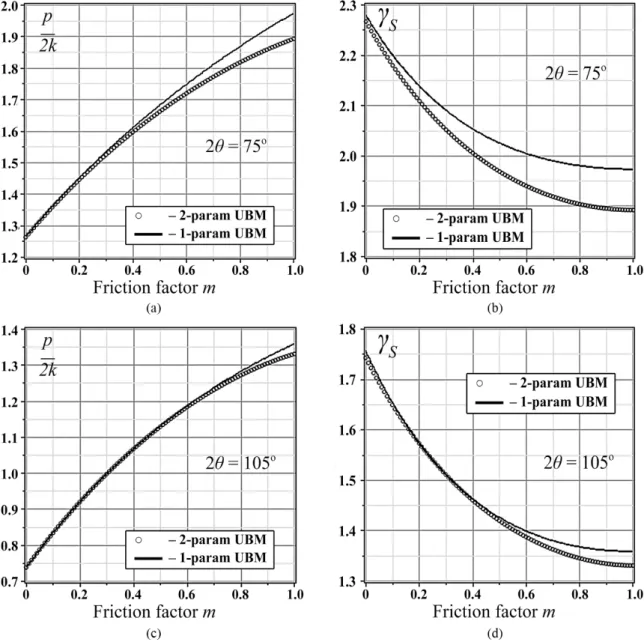
The obtained results (2)-(11), derived with two-parameter UBM introduction (○○○) have been compared with upper bound solution by Perig22 (▬▬) for relative punching pressure (p/2k)Perig and summary shear γPerig22 for 2θ=75° (Figures 8a,b), 2θ=105° (Figures 8c,d), 2θ=120° (Figures 9a,b), and 2θ=135° (Figures 9c,d):
( ) ( )
(
)
( )(
( ))
(
)
(
( ))
( )(
(
( )(
(
( )( ))
)
)
)
( )(
( ))
( ) ( )(
( ))
( ) ( ) 2 one param 2 one param 2 2 tan cot cot ;2 tan cot
2 1 cot
; tan cot
tan tan 2 tan
. tan − −
+ ⋅ θ + θ −
= + ⋅ θ −
θ + θ −
⋅ + θ −
γ =
θ + θ −
+ + θ − θ ⋅ ⋅ + ⋅ + θ
=
+ ⋅ θ
S
1 x x
p m x
k x
x x
1 m 1 1 m 1
x
1 m
The results of the comparison have been presented in Figures 8-9 and in Table 4. Good agreement, especially for plastic shear γS, has been found, where δ is the averaged relative divergence of the computational results, which was evaluated by the formula:
(
1 2) (
1 2)
1 2
1
100% 2
− −
δ = + ⋅
UBM UBM UBM UBM
UBM UBM
R R R R
R R (13)
where R2UBM and R1UBM and in (13) are the values obtained by upper bound method formulae for two-parameter UBM (3), (6), (10) (R2UBM, ○○○) and one-parameter UBM (12) (R1UBM, ▬▬) respectively (Table 4).
The numerical plots for ECAE punching pressure p/2k, derived with Equations 3 and 6 for two-parameter UBM (●●●●●) and with (12) for one-parameter UBM (▬▬▬)
are shown in Figures 8a,c;9a,c. The relative discrepancy for two-way ECAE punching pressure UBM estimation in Figures 8a,c;9a,c is shown in Table 4. The comparative plots for ECAE accumulated plastic shear γS , derived with Equations 10 and 6 for two-parameter UBM (●●●●●) and with (12) for one-parameter UBM (▬▬▬) are outlined in Figures 8b,d;9b,d. The relative discrepancy for two-way ECAE plastic shear UBM estimation in Figures 8b,d;9b,d is also shown in Table 4.
The value of the accumulated plastic shear (Figures 8b,d;9b,d) decreases with increasing friction factor. This general trend is assumed to be caused by additional metal sticking to the die walls during ECAE without lubrication. The area of dead metal zone CEDF increases with friction growth. In such
cases with maximum friction takes place the destruction of
Figure 8. Computational dependencies of ECAE punching pressure p/2k (a, c) and the total plastic shear γS (b, d) with respect to friction
factor m for the ECAE Segal 2θ-dies with 2θ=75°(a, b) and 2θ=105°(c, d), derived by two-parameter UBM (○○○), and one-parameter
Figure 9. Computational dependencies of ECAE punching pressure p/2k (a, c) and the total plastic shear γS (b, d) with respect to friction
factor m for the ECAE Segal 2θ-dies with 2θ=120°(a, b) and 2θ=135°(c, d), derived by two-parameter UBM (○○○), and one-parameter
UBM (▬▬).
Table 4. Comparison of upper bound-estimated computational results for ECAE punching pressure p/2k and total accumulated plastic strain γS derived with the introduction of two-way UBM techniques for Segal 2θ-dies.
δ 2θ=75º 2θ=90º 2θ=105º 2θ=120º 2θ=135º
2-param UBM vs. 1-param UBM
δ(p)=2.852% δ(p)=3.012% δ(p)=1.233% δ(p)=1.568% δ(p)=17.849%
δ(γS)=3.426% δ(γS)=3.012% δ(γS)=1.434% δ(γS)=2.647% δ(γS)=8.496%
workpiece surface with formation of additional wrinkles and burrs at workpiece surface. These defects, together with the large dead zone and growing metal sticking violate the dynamics of macroscopic rotation within volume of worked material, which determines the value of accumulated plastic shear during ECAE. This causes above mentioned decrease of accumulated plastic shear (Figures 8b,d;9b,d) with the increase of the friction factor during ECAE through a Segal 2θ-die with 2θ>0° and 2θ<180°.
5. Comparison with Published Experimental
Results
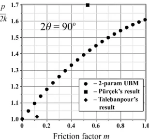
The results of the comparison of obtained two-parameter UBM values (3)-(4), (6) with published experimental data30,34 for ECAE punching pressure p/2k are shown in Figure 10, where ECAE die angle is 2θ=90º:
■ – G. Pürçek experiment in Figure 10 (Pürçek’s workpiece material was Zn–Al–12, Pürçek’s punching temperature was t=75±3 °C, Pürçek’s lubrication was molybdenum disulphide, Pürçek’s maximum punching pressure was
pMAX = 496 MPa, Pürçek’s yield stress was σS = 253 MPa,
results divergence between UBM (3)-(4), (6) and Pürçek’s experimental results in Pürçek32 is δ
G. Pürçek(p/2k)=16.48% as
is shown in Figure 10 as ■);
♦ – B. Talebanpour experiment in Figure 10 (Talebanpour’s workpiece material was commercially pure Aluminum, Talebanpour’s punching temperature was t=20 °C, Talebanpour’s lubrication was mineral oil, Talebanpour’s maximum punching pressure was pMAX = 140 MPa, Talebanpour’s yield stress was k = 69 MPa, results divergence between UBM (3)-(4), (6) and Talebanpour’s experimental ECAE punching pressure results in Talebanpour & Ebrahimi27 is δ
B. Talebanpour(p/2k)=9.76% as is shown in Figure 10 as ♦).
So good agreement of proposed two-parameter UBM approach with published experimental results has been obtained for an ECAE die with channel intersection angle 2θ=90º.
6. Conclusions
I. Physical simulation results for ECAE material low through a Segal 2θ-die with a channel intersection angle of 2θ>0° and 2θ<180° underline the complex geometry of dead zone for metal plastic low. This experimentally determined fact was the stimulus resulting in the introduction of the two-parameter UBM to the metal ECAE problem for metal workpiece forcing through Segal 2θ-die with channel intersection angle of 2θ>0° and 2θ<180°.
II. The application of the two-parameter upper bound method (UBM) in the form of two-parameter rigid block
method (RBM) with trial discontinuous velocity ield (DVF) to the analysis of ECAE through a Segal 2θ-die with 2θ>0° and 2θ<180° correctly describes the essential geometrical features for this SPD process, such as the appearance of a dead zone (DZ) and its increase as a function of external friction m.
III. Also the increase of ECAE punching pressure p/2k
and decrease of total plastic shear γS, resulting from an increase in friction m is well predicted with two-way ECAE
parameter computations. The two-parameter upper bound (UBM) results based on a discontinuous velocity ield (DVF) are in good agreement with the one-parameter upper bound solution results and published experimental results of Pürçek32 and Talebanpour & Ebrahimi27.
IV. The proposed two-parameter upper bound approach can be applied to further analysis of metal workpieces ECAE low through 2θ-dies with external and internal radii in the channel intersection zone as well as for the dies for equal channel multiple angular extrusion, where angular dies have additional pairs of intersecting channels.
7. Nomenclature
• SPD is Severe Plastic Deformation; • ECAE is Equal Channel Angular Extrusion; • RBM is Rigid Block Method;
• UBM is Upper Bound Method;
• one-parameter UBM assumes dead zone shape in the form of isosceles triangle CED without additional bottleneck EF;
• two-parameter UBM assumes dead zone shape CEDF
in the form of two adjacent triangles CEF & DEF with formation of additional bottleneck EF;
• DVF is Discontinuous Velocity Field; • DZ is Dead Zone;
• a is the channel width of the ECAE die, [m];
• 2θ is the channel intersection angle of the ECAE die, [deg];
• The 2θ-die is the angular die AEO–BEO with channel intersection angle 0°<2θ<180°;
• The 2θ-die of Segal geometry is the angular die AEO – BEO with channel intersection angle 0°<2θ<180° without external and internal radii in channel intersection zone;
• h = ax is the horizontal length of the dead zone CEDF, i.e. the horizontal projection of bottleneck EF, [m]; • x = h/a is the relative dimensionless horizontal length
of the dead zone CEDF, i.e. the irst independent
parameter for two-parameter UBM;
• H = ya is the vertical length of the dead zone CEDF
within inlet die channel AEO, i.e. the relative height of the dead zone CEDF, [m];
Figure 10. Comparison of theoretical results for relative punching pressure p/2k derived with two-parameter UBM for non-hardening
metal low through a Segal die with channel intersection angle 2θ=90° with published experimental results for relative punching pressure p/2k: ●●●●● – computational two-parameter UBM result
calculated according to (3)-(4), and (6); ■ – G. Pürçek experiment (results divergence is δG. Pürçek(p/2k)=16.48%[32]); ♦ – B. Talebanpour experiment (results divergence is δB. Talebanpour(p/2k)=9.76%
• y = H/a is the relative dimensionless vertical length of the dead zone CEDF within inlet die channel
AEO, i.e. the second independent parameter for two-parameter UBM;
• i, j = 1, 2, 3, 4, 5;
• α = α (x,y) and β = β (x,y) are the angular coordinates, determining the area and the shape of the dead zone CEDF, [deg];
• p is the Perig-derived ECAE punching pressure, obtained by the upper bound (UBM) theory with rigid blocks introduction, [Pa];
• σs is the low stress of the workpiece material, [Pa]; • k is the plastic constant of the workpiece material,
[Pa], where k= σS 3 (in this case we assume the 2D plastic low of the workpiece material, where the workpiece inlet and outlet die channels have rectangular cross sections);
• p / 2k is the dimensionless (relative) Perig-derived ECAE punching pressure, obtained by the upper bound (UBM) theory with rigid blocks introduction;
• m is the dimensionless plastic friction factor in the Siebel (Tresca) friction law, where 0 ≤ m ≤ 1;
• lAC = lDB are the lengths of friction zones;
• V1 is the workpiece material velocity in the inlet channel of the ECAE die, [m/s];
• V3 is the workpiece material velocity in the outlet channel of the ECAE die, [m/s];
• li-j are the lengths of common boundaries or interface joints for rigid blocks i and j within the rigid blocks partitioning scheme;
• [Vi-j] are the relative sliding velocities for blocks i and j, [m/s];
• Vn
i-j is a velocity component orthogonal to a discontinuity line li-j, [m/s];
• γi-j = [Vi-j]/ V n
i-j is the dimensionless value of plastic shear at the inclined discontinuity line;
• γs is the Perig-derived dimensionless value of total accumulated ECAE plastic shear, obtained by the upper bound (UBM) theory with rigid blocks introduction;
• δ is the relative dimensionless divergence (disagreement) of results, [%].
References
1. Abrinia K and Mirnia MJ. A new generalized upper-bound solution for the ECAE process. International Journal of Advanced Manufacturing Technology. 2010; 46(1-4):411-421. http://dx.doi.org/10.1007/s00170-009-2103-y.
2. Alkorta J and Sevillano JG. A comparison of FEM and upper-bound type analysis of equal-channel angular pressing (ECAP).
Journal of Materials Processing Technology. 2003; 141(3):313-318. http://dx.doi.org/10.1016/S0924-0136(03)00282-6.
3. Altan BS, Purcek G and Miskioglu I. An upper-bound analysis for equal-channel angular extrusion. Journal of Materials Processing Technology. 2005; 168(1):137-146. http://dx.doi. org/10.1016/j.jmatprotec.2004.11.010.
4. Eivani AR and Karimi Taheri A. An upper bound solution of ECAE process with outer curved corner. Journal of Materials Processing Technology. 2007; 182(1–3):555-563. http://dx.doi. org/10.1016/j.jmatprotec.2006.09.021.
5. Eivani AR and Karimi Taheri A. The effect of dead metal zone formation on strain and extrusion force during equal channel angular extrusion. Computational Materials Science. 2008; 42(1):14-20. http://dx.doi.org/10.1016/j.commatsci.2007.06.001. 6. Faraji G, Abrinia K, Mashhadi M and Hamdi M. An upper-bound analysis for frictionless TCAP process. Archive of Applied Mechanics. 2013; 83(4):483-493. http://dx.doi.org/10.1007/ s00419-012-0697-2.
7. Laptev AM, Perig AV and Vyal OY. Analysis of equal channel angular extrusion by upper bound method and rigid blocks model. Materials Research. 2014; 17(2):359-366. http://dx.doi. org/10.1590/S1516-14392013005000187.
8. Luri R, Luis CJ, León J and Sebastián MA. A new configuration for equal channel angular extrusion dies. Journal of Manufacturing Science and Engineering-Transactions of the ASME. 2006; 128(4):860-865. http://dx.doi.org/10.1115/1.2194555.
9. Luri R and Luis CJ. Study of the ECAE process by the upper bound method considering the correct die design. Mechanics of Materials. 2008; 40(8):617-628. http://dx.doi.org/10.1016/j. mechmat.2008.02.003.
10. Medeiros N, Moreira LP, Bressan JD, Lins JFC and Gouvêa JP. Sensitivity analysis of the ECAE process via 2k experiments design. Matéria. 2010, 15(2):208-217. http://dx.doi.org/10.1590/ S1517-70762010000200018.
11. Milind TR and Date PP. Analytical and finite element modeling of strain generated in equal channel angular extrusion. International Journal of Mechanical Sciences. 2012; 56(1):26-34. http:// dx.doi.org/10.1016/j.ijmecsci.2011.12.002.
12. Narooei K and Karimi Taheri A. A new model for prediction the strain field and extrusion pressure in ECAE process of circular cross section. Applied Mathematical Modelling. 2010; 34(7):1901-1917. http://dx.doi.org/10.1016/j.apm.2009.10.008.
13. Narooei K and Karimi Taheri A. Strain field and extrusion load in ECAE process of bi-metal circular cross section. Applied Mathematical Modelling. 2012; 36(5):2128-2141. http://dx.doi. org/10.1016/j.apm.2011.08.008.
14. Narooei K and Karimi Taheri A. Using of Bezier formulation for calculation of streamline, strain distribution and extrusion load in rectangular cross section of ECAE process. International Journal of Computational Methods. 2013; 10(03):1350005. http://dx.doi.org/10.1142/S0219876213500059.
15. Paydar MH, Reihanian M, Ebrahimi R, Dean TA and Moshksar MM. An upper-bound approach for equal channel angular extrusion with circular cross-section. Journal of Materials Processing Technology. 2008; 198(1-3):48-53. http://dx.doi. org/10.1016/j.jmatprotec.2007.06.051.
Science and Engineering A. 2010; 527(16–17):3769-3776. http://dx.doi.org/10.1016/j.msea.2010.03.043.
17. Perig AV, Zhbankov IG, Matveyev IA and Palamarchuk VA. Shape effect of angular die external wall on strain unevenness during equal channel angular extrusion. Materials and Manufacturing Processes. 2013; 28(8):916-922. http://dx.doi.org/10.1080/10 426914.2013.792417.
18. Perig AV, Zhbankov IG and Palamarchuk VA. Effect of die radii on material waste during equal channel angular extrusion.
Materials and Manufacturing Processes. 2013; 28(8):910-915. http://dx.doi.org/10.1080/10426914.2013.792420.
19. Perig AV and Laptev AM. Study of ECAE mechanics by upper bound rigid block model with two degrees of freedom.
Journal of the Brazilian Society of Mechanical Sciences and Engineering. 2014; 36(3):469-476. http://dx.doi.org/10.1007/ s40430-013-0121-z.
20. Perig AV and Golodenko NN. CFD Simulation of ECAE through a Multiple-Angle Die with a Movable Inlet Wall. Chemical Engineering Communications. 2014; 201(9):1221-1239. http:// dx.doi.org/10.1080/00986445.2014.894509.
21. Perig AV and Golodenko NN. CFD 2D Simulation of Viscous Flow during ECAE through a rectangular die with parallel slants. International Journal of Advanced Manufacturing Technology. 2014; 74(5-8):943-962. http://dx.doi.org/10.1007/ s00170-014-5827-2.
22. Perig AV. 2D upper bound analysis of ECAE through 2θ-dies for a range of channel angles. Materials Research. 2014; 17(5):1226-1237. http://dx.doi.org/10.1590/1516-1439.268114. 23. Perig AV, Tarasov AF, Zhbankov IG and Romanko SN. Effect
of 2θ-punch shape on material waste during ECAE through a 2θ-die. Materials and Manufacturing Processes. 2015; 30(2):222-231. http://dx.doi.org/10.1080/10426914.2013.83 2299.
24. Reihanian M, Ebrahimi R and Moshksar MM. Upper-bound analysis of equal channel angular extrusion using linear and rotational velocity fields. Materials & Design. 2009; 30(1):28-34. http://dx.doi.org/10.1016/j.matdes.2008.04.059. 25. Segal VM. Materials processing by simple shear. Materials
Science and Engineering A. 1995; 197(2):157-164. http:// dx.doi.org/10.1016/0921-5093(95)09705-8.
26. Segal VM. Slip line solutions, deformation mode and loading history during equal channel angular extrusion. Materials Science and Engineering A. 2003; 345(1-2):36-46. http://dx.doi. org/10.1016/S0921-5093(02)00258-7.
27. Talebanpour B and Ebrahimi R. Upper-bound analysis of dual equal channel lateral extrusion. Materials & Design. 2009; 30(5):1484-1489. http://dx.doi.org/10.1016/j.matdes.2008.08.006. 28. Tóth, L.S., Massion, R.A., Germain, L., Baik, S.C., Suwas, S.
Analysis of texture evolution in equal channel angular extrusion of copper using a new flow field. Acta Materialia. 2004; 52(7): 1885-1898. http://dx.doi.org/10.1016/j.actamat.2003.12.027.
29. Berta M and Prangnell PB. The effect of dispersoids and processing variables on grain refinement of aluminium alloys deformed by ECAE. Solid State Phenomena. 2006; 114:151-158. http://dx.doi.org/10.4028/www.scientific.net/SSP.114.151. 30. Farias, F.A., Pontes, M.J.H., Cintho, O.M. Processing of a
duplex stainless steel by equal channel angular extrusion.
Matéria. 2010, 15(2):345-354. http://dx.doi.org/10.1590/ S1517-70762010000200036.
31. Lucas, F.L.C., Guido, V., Käfer, K.A., Bernardi, H.H., Otubo, J. ECAE processed NiTi shape memory alloy. Materials Research. 2014, 17(Suppl. 1):186-190. http://dx.doi.org/10.1590/S1516-14392014005000034.
32. Pürçek G. Improvement of mechanical properties for Zn–Al alloys using equal-channel angular pressing. Journal of Materials Processing Technology. 2005; 169(2):242-248. http://dx.doi. org/10.1016/j.jmatprotec.2005.03.012.
33. Iwahashi Y, Wang J, Horita Z, Nemoto M and Langdon TG. Principle of equal-channel angular pressing for the processing of ultra-fine grained materials. Scripta Materialia. 1996; 35(2):143-146. http://dx.doi.org/10.1016/1359-6462(96)00107-8. 34. Johnson W and Kudo H. The mechanics of metal extrusion.
Manchester University Press; 1962.