Volume 24, N. 3, pp. 487–490, 2005 Copyright © 2005 SBMAC ISSN 0101-8205
www.scielo.br/cam
Erratum:
(Computational and Applied Mathematics, Vol. 22, N. 3, pp. 359–395)
Steam injection into water-saturated porous rock
W. LAMBERT1, J. BRUINING2 and D. MARCHESIN1
1Instituto Nacional de Matemática Pura e Aplicada, Estrada Dona Castorina 110, 22460-320 Rio de Janeiro, RJ, Brazil
2Dietz Laboratory, Centre of Technical Geoscience, Mijnbouwstraat 120, 2628 RX Delft, The Netherlands
E-mails: [email protected] / [email protected] / [email protected]
Abstract. The Riemann problem for steam injection at boiling temperature into a porous
medium saturated with water was solved in[1]. Here, we correct the Riemann solution for case III and redraw the speed diagrams 3.1, 3.4 and 4.5. We redraw also the solution in case III, Figure 4.4.
Mathematical subject classification: 76S05, 35L60, 35L67.
Key words: Porous medium, steamdrive, Riemann solution, balance equations, multiphase
flow.
#558/02. Received: 28/XII/02. Accepted: 18/VIII/03.
488 ERRATUM: STEAM INJECTION INTO WATER-SATURATED POROUS ROCK
In[1], cases I and II are correct, but there are some mistakes that influence the solution in case III. The first relevant mistake is the statement that the saturation
S†maximizesvSC F (Remark 11). The correct statement is:
Theorem 1. There are two saturation values that satisfy Eq. (3.7) in[1]for each fixed T < Tb. The smallest S†minimizesvSC F. The other S††maximizes vSC F, but it is irrelevant.
Moreover the solution is stable if we vary the left state, it follows that:
Corollary 1. In the limit as SL tends to zero, the wave speedvgb,w in the hot
region given by Eq. (2.8) in[1]converges to zero, so the solution for the Riemann problem reduces a cooling discontinuity in the liquid water region.
From the above Theorem and Corollary, we see that the Figures 3.1 and 3.4 in
[1]contain an error; we correct them in Figure 1.
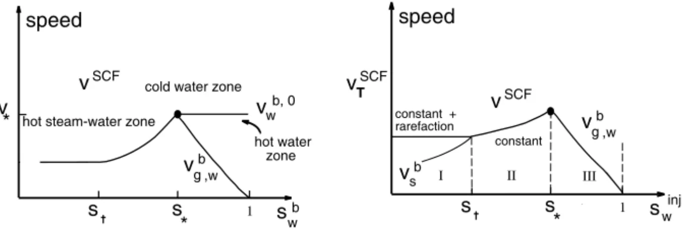
Figure 1 –a)-Left:Corrected schematic bifurcation nearS∗(for fixedu0,T0versusSb
w. The shock speedSC Fis minimum atS†; the shock speedvgb,w tends to zero whenSwb
tends to 1. b)-Right: The corrected structure of steam-water zone below solid curve marked byvbs,vTSC F,vSC F given in Eqs. (2.7), (2.24) with Sw = S†, Eq. (2.24) with
S†<Si n j <S∗, and Eq. (2.8) respectively. The figures are not drawn to scale.
The wave speed diagram in Figure 4.5 of[1]contains an error also. The correct diagrams are given in Figure 2. There are two diagrams because the saturation shock speed and the thermal shock are different for injected saturations larger than
S∗. These diagrams are drawn out of scale for illustrative purposes, because the characteristic speedvsgcan be much larger than the other wave speeds. Figs. 3.1
W. LAMBERT, J. BRUINING and D. MARCHESIN 489
and 3.4 in[1] contain an error also; those figures were summarized in Figure 4.5 in[1], which is corrected here in Figure 2. The Riemann solution for the cases I and II are correct, however the Riemann solution for case III contains an error. The mistake is the statement that the saturation shock speedλbs is faster thanvSC F in cases I and II. The correct statement is thatvb
g,w speed converges
to zero if the water saturation at the left state tends to zero, as summarized in Corollary 1 above. The thermal wave speed is drawn in Figure 2.a) and in 2.b) we draw the saturation wave speed.
Figure 2 –a)-Left: The diagram represents the thermal wave speed; b)-Right: The diagram represents the saturation wave speed. They correct the diagram presented in Figure 4.5 of [1]. In both, the solid curve represents the wave speeds used in the Riemann solution. The characteristic speedvbs, Eq.(2.7), is the Buckley-Leverett characteristic speed in the hot region; the shock speedvbg,wis the HISW speed, Eq.(2.8), and represents the Buckley-Leverett shock for a water saturationSwtoSw=0;vSC Fis the condensation shock speed between the hot region and the liquid water region, Eq.(2.24);vwb,0is the cooling contact discontinuity speed in the liquid water region, Eq.(2.15). Notice that the temperature shock speed tends tovWT when water saturation tends toSw =1 (liquid water region) and the saturation shock speed tends to zero, thus the solution converges to the solution in the liquid water region.
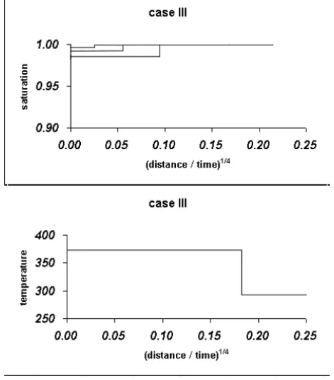
The solution diagram for case III given in Figure 4.4 of[1]must be modified. The strength of saturation shock tends to zero when the injection saturation tends to 1, while the speed of cooling discontinuity does not change. In Figure 3 we show the schematic solution for case III for three different injection saturations.
490 ERRATUM: STEAM INJECTION INTO WATER-SATURATED POROUS ROCK
Figure 3 – Steam injection for three high water saturation values. We get a constant state upstream, the Buckley-Leverett saturation shock and the cooling discontinuity. These waves have distinct speeds; notice thatvbg,wtends to zero when the injection saturation tends to 1, while the speed of cooling discontinuity does not change.
REFERENCES
[1] Bruining J., Marchesin D. and Van Duijn C.J.Steam Injection Into Water-Saturated Porous Rock.Computational and Applied Mathematics,22(3) (2003), 359–395.
[2] Lambert W.Doctoral Thesis: IMPA, 2006, in preparation.
[3] Lambert W., Marchesin D. and Bruining J.The Riemann Solution of the balance equations for steam and water flow in a porous medium, submitted to Methods and Applications of Analysis 2005.