BIM MODELING FOR CONTRACTORS - IMPROVING
MODEL TAKEOFFS
André Monteiro, Research Assistant, agcm@fe.up.pt
Department of Civil Engineering, University of Porto, Portugal
João Poças Martins, Auxiliary Professor, jppm@fe.up.pt
Department of Civil Engineering, University of Porto, Portugal
ABSTRACT
As industry stakeholders investigate on the best uses for Building Information Modeling (BIM), its shortcomings begin to be realized, the need for modeling parameterization becomes more evident and methods to better approach these issues developed. Automatic quantity takeoff is one of the most important BIM-based features. Research conducted by the authors shows that in order to be successfully used, quantity takeoff requires specific model definition. Adapting a model for quantity takeoff, may, however, affect the design for other purposes. This paper surveys different approaches to BIM design, exploring the implications of each method on the outputs of the model, and taking in account the two most important types of takeoff for contractors: drawings and quantities.
Keywords: quantity takeoff, drawing, contractor, modeling specifications, BIM
1. INTRODUCTION
Building Information Modeling (BIM), the process of generating and managing building data during its life cycle (Lee, Sacks et al. 2006), has been gaining increasing awareness in the Architecture, Engineering and Construction (AEC) industry (Howard and Björk 2008; McGraw-Hill 2008; McGraw-Hill 2009; Froese 2010; McGraw-Hill 2010). Based on a virtual and "intelligent" tridimensional model that integrates the life-cycle information of the building in an interactive data-base, BIM applications have a set of features that provide many instant benefits for the user, regardless of the purpose for the model being architectural or engineering design, project management, construction planning or facilities management. Common BIM applications include (Eastman 2008): 3D visualization, quantity takeoff, drawing takeoff, clash detection, model analysis for different domains, construction planning and cost estimation.
Using BIM as a central database means data exchange between different models. According to some studies, the lack of software interoperability is one of the issues with most potential negative impact (Gallaher, O'Connor et al. 2004; AIA California Council and AIA National 2007). The Industry Foundation Classes (IFC) (BuildingSMART 2011), a standard data structure for the definition of AEC information model elements (Eastman, Lee et al. 2009), is currently the best answer to this issue. Although the format does not grant full compatibility between different models, it does cover a considerable portion of the modeling needs. Information input and management is the other major issue, as it is necessary to control the amount of information that is added to the model, the level of detail, the organization of the building elements and the role of everyone who has access to the model. Authoring entities and organizations in several countries are releasing modeling procedures, best practice guidelines and BIM standards to address these concerns and provide standard workflows for each BIM-based environment (GSA 2007; Kiviniemi, Rekola et al. 2007; NIBS 2007; Statsbygg 2007; ICE 2009; Det Digitale Byggeri 2010; NATSPEC 2011; U.S. Army Corps of Engineers 2011).
SIGABIM is a research project that brings together the contribution of different Portuguese entities, namely, the University of Porto, Mota-Engil Engenharia (largest contractors in Portugal) and
th
Arquifam (an architecture office). Motivated by the need to reduce costs and increase productivity in construction, the aim of this project is to lead the BIM implementation process in Portugal. The performance of several BIM applications has been tested. Frameworks for BIM application were developed and put to practice in several projects, in a controlled environment (Monteiro and Martins 2012). Some specific studies like the one presented in this article have also been developed under the research project. In our project, Graphisoft's ArchiCAD (Graphisoft 2012) is the most used application for BIM design, and Vico Office/Vico Control the applications used for production planning and control, and cost estimation. This article reports the preliminary findings of an ongoing large scoped case study. As the project has not been yet concluded, there is not enough data available to perform an accurate and representative statistical analysis. The issues presented in the article were identified during previous case studies and represent one of the major subjects being tested in the case study.
2. HOW IS BIM BEING USED IN THE CURRENT PRACTICE
BIM was developed to be used as a centralizing database for the AEC information during the project's life cycle (Eastman 1999). Every stakeholder is meant to bring their own inputs during the early stages of the project so that the model continuously evolves in a consistent matter. Each stakeholder would use the application of their choice, and through a common format, share the data with the central model, assembling all the information in one place. In practice, interoperability issues prevent this flow from operating flawlessly (Ma, Ha et al. 2006).
BIM is, in most aspects, in its early stages of implementation (Howard and Björk 2008; Gu and London 2010; McGraw-Hill 2010; Barlish and Sullivan 2012). Even those who already work with BIM, often do it in an isolated way, meaning, the BIM user creates the model and only shares the results, not the actual model: e.g. provides drawings, quantities, design changes based on a clash detection analysis, etc. While BIM is still not implemented on a large scale, architects, engineers, contractors, owners and manufactures are each trying to find the best way to work with BIM models, and how they can extract more benefits from them. Nowadays, it is more accurate to think of BIM as a series of different models for each stakeholder, rather than an unique one. The most important types of BIM model are (AGC 2006):
x Architectural model x Structural model x MEP model x Contractor's model
As different approaches have different implications, aggregating models from the different domains in one unique model is not straightforward. The ideal method would be to work continuously on the same model so that the data is better assembled and the information organized, however, that is usually not possible, mostly due to interoperability issues. Since the architectural, the structural and the MEP model each come from a different source, the contractor can either try and assemble the different models into one or create a new model from scratch based on the existing ones. Creating a new model may seem unnecessary work but it is a way of guaranteeing that the elements are modeled according to the correct specifications - which are usually defined by internal standards/guidelines for each contractor. The model will thus respond better for specific uses like quantity takeoff. On the other hand, design errors are more likely to be identified when the model is under development.
Available research on quantity takeoff includes (Faraj, Alshawi et al. 2000; Staub-French, Fischer et al. 2003; Yabuki and Shitani 2005; Kiviniemi, Rekola et al. 2007; Eos Group 2008; Kim, Chin et al. 2009; Firat, Arditi et al. 2010; Sattineni and Bradford II 2011; Zhiliang, Zhenhua et al. 2011). Ranging different analysis all related to quantity takeoff, model dynamics for quantity takeoff and drawings takeoff is however not approached in detail in any of the mentioned studies.
3. BIM MODELING FOR CONTRACTORS
The contractor's model is mainly used for (Eastman 2008):
x Visualization: this includes navigating the model to better understand the spatial dispositions of the building, to get 3D representations of complex situations and to perform a quality as-sessment of both the project's design and of the BIM model. It also includes the generation of 2D drawings to be used on site during the construction phase;
x Quantity takeoff: automatically extracting quantities to be used for cost estimation, construc-tion planning and producconstruc-tion control, and for tendering.
Due to time and cost limitations, as well as other limitations regarding BIM applications, it is very hard to produce a model that is able to equally satisfy both needs. Unlike the traditional practice where the quantity surveyor freely measures the project based on the 2D drawings, the BIM-based automatic quantity takeoff is constrained by the parameters provided by the application to configure the measurement of each element. In other words, the application will only measure the elements in predefined ways. In most cases, BIM quantities can be extracted according to the specifications established by internal, local or global standards, or even by suppliers. Whenever this is not possible, the element must be modeled differently and the measurement parameterization adjusted so that the takeoff matches the desired specification.
Adapting a model for quantity takeoff may require changing the design in some elements -replacing a complex element for simple geometric forms from which is possible to extract accurate quantities. Adjusting the model for quantity takeoff, therefore, may make the model cease to be an exact visual representation of the building. On the other hand, if modeling cost expenses are to be minimized, many details should be disregarded as they are either irrelevant or they strain the takeoff parameterization. An example would be to measure the total amount of glass in the project. Glass is often attached to other elements such as doors, windows or curtain-walls, and since most applications cannot differentiate between the glass and the frame, the surveyor can only extract total quantities for the opening, thus compromising the measurement. To solve this situation, instead of adding a window, the modeler can instead add the glass and the frames separately, modeling each component with another tool, e.g. the "Wall" tool. There are other ways to solve this issue. The amount of glass in a window could be measured independently and added as a text-based field to the object, or, the modeling object in question, e.g. the "Window" tool, could be re-configured in order to measure and provide the glass percentage or glass area.
It is recommended to separate structural elements from architectural elements in the model - e.g. separate the concrete from the plaster in a column. Many BIM tools are designed to have the structural elements include the finish. However, it is good practice to model each element separately so that it becomes easier to isolate them, thus making sure that it is possible to completely isolate structural elements from architectural elements. The goal is to have a definitive structure where the architectural elements are built upon. This methodology mirrors the actual construction process. Since the structural model is created before the architectural one, the contractor can start building the foundations and the superstructure before the architectural and MEP design are added to the model -although not recommendable, this is a common scenario due to cost and schedule limitations. On the other hand, some architectural elements like doors and windows, footers, moldings and coatings, are often changed during the construction phase. These changes in design need to be included as fast as possible into the contractor's model, since they will feed other applications the resources needed for production planning and control. Since the structural model is independent from the other domains, there is no risk of changing the structure when architectural design changes are added to the model, making this approach less prone to error.
3.1.1 The importance of the Warehouse and the Content Plan
A BIM element is defined by two different types of data: geometric and analytic. Geometric data is used to define the shape of the element and the spatial constraints. Analytic data is used to configure the visual representation of the element, as well as model specifications for data exchange or data extraction.
Considering all the different types of compositions in a project, it is good practice to create a template with the desired configurations for each type instead of creating a new type whenever a new configuration appears during the modeling process. With this approach, and assuming the model is
th
built over existing 2D drawings, the design is analyzed before the modeling process, allowing for a better and more consistent data processing, i.e. all the data is gathered and consistently processed in an organized way. Instead of modeling while analyzing the different views to find out the element's configuration, there is already a map of the drawing with the location of the different elements of the template. The modeling process is therefore expedited.
The assembly of all the templates for each type of element is called the Virtual Warehouse. The Warehouse can be created as a set of favorites (for Graphisoft's ArchiCAD (Graphisoft 2012)), as a set of families (for Autodesk's Revit Architecture (Autodesk 2012)) or by modeling each type on the building model (for any application) - see Figure 1 for an example of this type of Warehouse built on ArchiCAD.
Figure1: Example of a virtual warehouse in ArchiCAD.
The Content Plan links the Warehouse elements to the project's specifications. By creating the Warehouse and the Content Plan before modeling the project, the design process becomes simpler and more accurate, as eventual errors and omissions in both documents are likely to be identified earlier. Plus, since the data is only entered once, upon the creation of the Warehouse, there is less risk of compromising the modeling process.
3.1.2 Modeling walls and floors: the problem with compositions
Figure 2: Different types of compositions per element.
One of the major issues about BIM modeling is managing compositions. Most BIM tools are designed to represent a wall or a floor as a single element with a specific composition. In practice, the element's configuration can be seen in 2D sections, and all individual layers measured for thickness, surface area and volume. However, the model will still read the element as an individual object, which means, besides thickness, all the other measures will be the same for every layer of the composition. The issue here is that the composition's configuration is not always the same along its height or length. Figure 2 illustrates this by showing an example of a wall that only has the finish layers - drywall and painting - until the false ceiling. In terms of modeling, this problem can be approached in different ways:
x Model each layer/material separately
x Model the structure separately and the rest as a different composition x Model the composition 1 and the composition 2 separately
x Model only the composition 2 from floor to ceiling
The different modeling solutions have different implications - different modeling times, and different quantities and drawings extracted. The first two methods represent the most viable choices in terms of cost-benefit. As this study is framed in a contractor's perspective, each of these solutions will be placed in that context and analyzed in further detail over the next sub-chapters.
Quantity takeoff is not an end in itself. It is a feature that will fuel other activities, such as production planning and control, cost estimation, bidding, tendering, to name the most important. The current choice in terms of applications to process and work the takeoff data is very limited. Added to that the ability to divide the model and associate data to different locations and it comes down to only one application that can provide all these features in one package: Vico Office (Vico Software 2012). The application operates by importing IFC models. Compositions are translated into IFC properties, solely in text form, which means the only measure that is readable by the importing application is the thickness. To extract the volume and the surface area - the last one being the standard unit for wall measuring - the user must manually input the formula in the application. The problem is that Vico Office sometimes generates errors when trying to extract the length of the wall due to some conflicts to interpret which is the reference side of the wall. Modeling compositions for quantity takeoff is, therefore, with the current available solutions, one of the major limitations in BIM design.
4. PROPOSED METHODS
4.1 Method one - Separate each material
The most detailed approach is to model each layer individually - each layer is modeled as a different composition made of a single material. With this method, the user is able to fully control the modeling process as he ceases to be constrained by the height or length of the main wall - see Figure 3 for a visual representation of this method.
Figure 3: Example of all the materials modeled separately.
The user is able to quickly isolate each type of elements, which is something extremely useful to be able to visualize the structural elements or to identify the location of a given element, e.g. a specific insulation material or a specific plaster. This kind of feature is also possible when using multi-layered compositions but it is much trickier to obtain the pretended result, and in some cases, it is just not possible to isolate the elements as desired. The ability to quickly isolate elements and properties is also very useful for quantity takeoff, as the parameterization of the takeoff features is more complex than the parameterization for visualization.
th
Modeling each layer separately is one way of overcoming the limitations of using IFC models for quantity takeoff - see [3.1.2] as each material will correspond to a single element/object with unique geometry.
Comparing to the others, this method is characterized for its superior flexibility and higher detail, however, it is not without its disadvantages. As all the layers are assembled as single elements, the model becomes heavier - more data makes the model processing slower. Also, as applications are designed to incorporate different materials as a single composite element, using this approach can compromise the model's consistency if the elements are not assembled in the right way. The user needs to be extra careful with the connections between elements, both in 3D - more geometric configurations to define, and in 2D - defining the correct set of colors and priorities for each material in order to make sure that the layers for each type of material are properly connected in the 2D sections. This can lead to an increase in the modeling time, ultimately translated in a more expensive model.
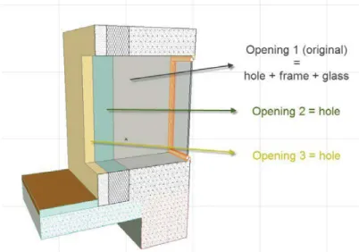
Modeling openings - windows and doors - is perhaps the biggest disadvantage to this method. Modeling an opening in a BIM model is an automatic process, meaning, the user configures the geometry and the properties of the element and simply inserts it in the wall. When the wall is not a single element but a series of elements placed continuously together, automatically inserting the opening in all the layers at the same time is not possible. This is solvable in a manual way, by adding empty openings with the same geometry in the adjacent layers of the wall - see Figure 4, or by manually adjusting the geometry of these layers. Openings are some of the most commonly changed elements during the design's late stages or even during the construction phase. Adding design changes to openings modeled with this method can be an exhaustive task since the work is multiplied by the number of layers that compose the wall.
Figure 4: Modeling windows with the multi-layer approach.
4.2 Method two - Structure separated from other compositions
This method emerged as a more economic alternative to the previous method. Following the requirements for contractor's BIM models as defined in [3.1], the structural model must be independent from the architecture one. As such, the architectural and MEP elements are modeled after and based on the structural model. If a wall or a floor contains structural elements and at least one more material, the structural element will be left untouched and the other layers will be added as compositions. This means that, in that case, a single wall - as a building element - may be an assembly of at most three compositions - see Figure 5.
Figure 5: Example of a multi-composition wall.
Situations similar to the one represented in Figure 2 are an issue for structural walls with masonry or similar materials, like insulation or acoustic elements, because these materials go from floor to ceiling while the finish layers stop at the false ceiling. Separating the masonry from the finish requires the creation of an additional composition. To avoid this, the composition (masonry + finish) is modeled from floor to ceiling. For quantity takeoff purposes, a margin of error is admitted for the finish that stays above the false ceiling.
Unlike the previous method in which the warehouse is created solely based on the project's specifications, this method requires a location-based review to create the different compositions. The ID chosen for each composition is then added to the respective location in the drawing that is the base for the model, resulting in a substantially faster modeling process.
The fact that elements are attached to each other means that the modeling process is more constrained, therefore more prone to the use of tools such as "Solid Elements Operation" for ArchiCAD, which aid in the modeling of complex geometries by adding or subtracting parts of an element. This is an example of an exclusive feature for ArchiCAD. The use of exclusive features may lead to conflicts when the model is exchanged with different application which is why, for the purpose of modeling for quantity takeoff, such features are avoided.
This method takes less time to update the model. The number of elements is decreased and the data is more compressed - the information of many layers is compressed into a single one composition.
Updating the Warehouse during the modeling phase is a sensible task as the Content Plan must also be updated. Without the systematization of a continuous process, this task is more prone to errors and omissions during the modeling phase.
Issues with openings do not completely disappear however they are considerably downsized as they only apply to structural walls. Furthermore, the number of compositions per wall is at most three, contrarily to the previous method where a wall could have more than four layers.
Isolating elements is not straightforward. The structure can be easily isolated from other elements. Depending on the software, isolating finish materials may or may not be possible. Isolating masonry is the bigger issue. Masonry layers are attached to both finish layers and other layers such as air space of supporting frames. It is possible to isolate masonry elements using a combination of different identification definitions, however, it requires a significant amount of parameterization when compared to structural elements.
Quantity takeoff is less accurate than the previous method but considering the cost-benefit relation between level of detail and time spent to model, the loss in accuracy of the takeoffs was considered acceptable during our studies, given the increase in cost expenses.
4.3 Method three - Different compositions separately
This method consists in modeling all the different compositions separately. Taking once again the example of the Figure 2, this would mean that the wall would be an assembly of two compositions at different heights. While this method has the advantage of being more accurate than the previous one, it is also much more error prone, given the different elevations - the projection of the different walls on the floor plans coincide, therefore, it is easy for the user to think he is configuring the right element
th
when he is not - modeling openings is an example of how easy is to commit an error, as the user may enter the opening on the wrong composition. Flagrant errors are easily detected during the model's quality assessment, however, minor errors can pass unnoticed in less detailed inspections and may influence the drawings and the quantities extracted.
Another downside to this method is the number of different compositions that exist in a project. Not only this fact will increase the time needed to analyze the design, build the warehouse and locate the compositions, it will also slow down the modeling process.
With this method, the elements become more constrained and the information is more compacted which means it is harder to adjust the model to complex designs and to maintain the accuracy of the 2D drawings for high levels of detail. It is also harder to extract quantities from the model due to the problems with IFC and Vico as mentioned in [3.1.2].
4.4 Method four - Only main compositions
A simplification of the previous method, this approach is the most simple of all the methods. Instead of building the architecture upon the structure, the model is created from scratch, with each composition having both structural and architectural elements. As this method follows the original philosophy of most BIM applications, the model becomes more consistent - the elements are better connected between them, the data is better organized and the model becomes lighter. The overall look of the model in 3D is improved and so are most low detailed 2D drawings.
T he method is not without its weaknesses though. There are more constraints between the elements and more information is compacted into a single object. Isolating types of elements or properties for purposes of visualization or takeoff becomes harder and exchanging information through IFC a bigger issue.
With the current BIM tools, the current practice in design and information management, and the current requirements for project specification, it is still not feasible to use this method to create BIM models for the purposes discussed in this paper.
5. CONCLUSIONS
BIM ranges many possible applications. Keeping the very same model consistent and feasible for different applications is only possible with tight specifications for BIM design. Although quantity takeoff is one of the most important uses for contractors, it is yet still very vulnerable to interoperability issues. On the other hand, the takeoffs are not yet fully compatible with current national or project specifications for building measurements. In order to control the takeoff output, while maintaining an acceptable balance between quantity takeoffs and drawing takeoffs, BIM design must be controlled through the definition of modeling procedures. This article surveyed four different methods, each of which requires a different level of detail, and has its strengths and weaknesses. Table 1 resumes the major conclusions for each method based on the experienced acquired during our research project.
Table 1: Summary of the finding for each proposed method.
METHOD DESCRIPTION ONE- SEPARATE
EACH MATERIAL TWO - STRUCTURE SEPARATED FROM OTHER COMPOSITIONS THREE- DIFFERENT COMPOSITIONS SEPARATELY
FOUR- ONLY MAIN COMPOSITIONS
Level of detail High Medium Fairly high Low
Isolating elements/materials Easy Moderate Hard Hard Modeling constraints Few Moderate Several Several
Modeling openings Hard Fairly hard Fairly easy Easy
IFC compatibility High Medium Low Low
Quantity takeoff Simple Medium Hard Hard
Drawing takeoff/2D look Good Fairly good Fairly good Fairly good
Time/cost expenses High Medium Medium Low
Pre-modeling analysis Low High High High
Data organization Dispersed Moderate Moderate Compacted Navigation Slow Moderate Fairly slow Fairly fast Model update Hard Fairly hard Fairly easy Easy
There are not enough surveys regarding this matter to establish definitive and representative conclusions about which one is the better method, as it is dependent on the cost-benefit relation between time spent to create the model and the gains, also measured in time, from using more or less detailed takeoffs. The methods analyzed in this paper are currently being tested in a project for a five floor office building in Portugal. As the modeling phase is still in progress, there are still not enough results to conclude anything for the cost-benefit relation between methods, however, early findings confirm that method two takes less time to model than method one. Methods 3 and 4 were disregarded from the start, as the downsides for both methods make them unfeasible to our standards for quantity takeoff.
These conclusions are based on currently available technology. The development of plug-ins or other modeling tools may improve the productivity of modelers when developing more detailed models.
With a very narrow scope, this study serves as an example of improvements to be made for current BIM applications. Until the moment these issues are approached and solved by software developers, design rules for BIM modeling will still have to be followed in order to overcome limitations regarding BIM-based quantity takeoff.
ACKNOWLEDGEMENTS
We would like to highlight Vico Software's contribution in their continuous support to the SIGABIM project. We would also like to thank Agência de Inovação for funding our project.
REFERENCES
AGC (2006). "The Contractors' Guide to BIM." Associated General Contractors of America Edition 1.http://www.agcnebuilders.com/documents/BIMGuide.pdf
AIA California Council and AIA National (2007). "Integrated Project Delivery: A Guide." Autodesk (2012). "Autodesk Revit Products." from http://usa.autodesk.com/revit/.
Barlish, K. and K. Sullivan (2012). "How to measure the benefits of BIM — A case study approach." Automation in Construction 24(0): 149-159.http://www.sciencedirect.com/science/article/pii/S0926580512000234
BuildingSMART (2011). "IFC Overview." buildingSMART, International home of openBIM, Model Support Group, Imprmentation Support Group.http://buildingsmart-tech.org/specifications/ifc-overview
Det Digitale Byggeri (2010). "Digital Construction a Danish Government Initiative."
Eastman, C. (2008). BIM handbook a guide to building information modeling for owners, managers, designers, engineers and contractors. New Jersey, John Wiley and Sons Ltd.
Eastman, C., J.-m. Lee, et al. (2009). "Automatic rule-based checking of building designs." Automation in Construction 18(8): 1011-
1033.http://www.sciencedirect.com/science/article/B6V20-4X5HY5M-1/2/3bc8600bac432ff7a8ec020e7e0f3e09
Eastman, C. M. (1999). Building product models computer environments, supporting design and construction. New York, CRC Press.
Eos Group (2008). "Building Information Modeling: A Cost Estimating Perspective."
Faraj, I., M. Alshawi, et al. (2000). "An industry foundation classes Web-based collaborative construction computer environment: WISPER." Automation in Construction 10(1): 79-99.http://www.sciencedirect.com/science/article/pii/S0926580599000382
Firat, C. E., D. Arditi, et al. (2010). "Quantity Take-Off in Model-Based Systems."
Froese, T. M. (2010). "The impact of emerging information technology on project management for construction." Automation in Construction 19(5): 531-
538.http://www.sciencedirect.com/science/article/B6V20-4XXNV5M-1/2/303dd795c03767fecbdaa3b6115be046
Gallaher, M. P., A. C. O'Connor, et al. (2004). "Cost Analysis of Inadequate Interoperability in the U.S. Capital Facilities Industry." National Institute of Standards and Technology (NIST), Gaithersburg, MD, USA.http://www.arc-corporate.com/_pdf/NISTstudy.pdf
th
Graphisoft (2012). "ArchiCAD." from http://www.graphisoft.com/.
GSA, U. S. G. S. A. (2007). "BIM Guide For Spatial Program Validation." The National 3D-4D-BIM Program Office of the Chief Architect, Public Buildings Service, U.S. General Services Administration.http://www.gsa.gov/portal/content/105075
Gu, N. and K. London (2010). "Understanding and facilitating BIM adoption in the AEC industry." Automation in Construction 19(8): 988-999.http://www.sciencedirect.com/science/article/B6V20-5186RB4-1/2/bddc75d5549b2fa69008ff545875682a
Howard, R. and B.-C. Björk (2008). "Building information modelling – Experts’ views on standardisation and industry deployment." Advanced Engineering Informatics 22(2): 271-280.http://www.sciencedirect.com/science/article/pii/S1474034607000201
ICE (2009). "Collaborative Production or Architectural Engineering and Construction Information: BS1192:2007." Institution of Civil Engineers
Kim, S.-A., S. Chin, et al. (2009). "Automated Building Information Modeling System for Building Interior to Improve Productivity of BIM-based Quantity Take-Off." Information and Computational Technology
Kiviniemi, A., M. Rekola, et al. (2007). "Senate Properties: BIM Requirements 2007 – Quantity take-off."
Kiviniemi, A., M. Rekola, et al. (2007). "BIM Requirements 2007 in Different Phases of the Design and Construction Process." Senate Properties BIM Requirements
Lee, G., R. Sacks, et al. (2006). "Specifying parametric building object behavior (BOB) for a building information modeling system." Automation in Construction 15(6): 758-
776.http://www.sciencedirect.com/science/article/B6V20-4HPD3N7-1/2/9683c99dd7458028c568690df341d25d
Ma, H., K. M. E. Ha, et al. (2006). Testing Semantic Interoperability, University of Auckland.
McGraw-Hill, C. (2008). Building Information Modeling (BIM) - Transforming Design and Construction to Achieve Greater Industry Productivity. SmartMarket Report. C. McGraw-Hill. McGraw-Hill, C. (2009). "The Business Value of BIM - Getting Building Information Modeling to
the Bottom Line." SmartMarket Report
McGraw-Hill, C. (2010). "The Business Value of BIM in Europe." SmartMarket Report
Monteiro, A. and J. P. Martins (2012). "SIGABIM: a framework for BIM application." Proceedings of the XXXVIII IAHS World Congress - Visions for the Future of Housing Mega Cities April 16-19, 2012 Istanbul Technical University
NATSPEC (2011). "NATSPEC National BIM Guide." NATSPEC Construction Information Systems Limited ABN 20 117 574 606
NIBS (2007). "United States National Building Information Modeling Standard: Version 1 - Part 1: Overview, Principles, and Methodologies." buildingSMARTalliance, National BIM Standard Final Report
Sattineni, A. and R. H. Bradford II (2011). "Estimating With BIM: A Survey of US Construction Companies."
Statsbygg (2007). "Statsbygg goes for BIM."http://www.statsbygg.no/Aktuelt/Nyheter/Statsbygg-goes-for-BIM/
Staub-French, S., M. Fischer, et al. (2003). "A generic feature-driven activity-based cost estimation process." Advanced Engineering Informatics 17 (1): 23–39
U.S. Army Corps of Engineers (2011). "CAD BIM Technology Center." https://cadbim.usace.army.mil/BIM
Vico Software (2012). "Virtual Construction."http://www.vicosoftware.com/
Yabuki, N. and T. Shitani (2005). "A management system for cut and fill earthworks based on 4D CAD and EVMS." Computing in Civil Engineering, Proceedings of the 2005 ASCE International Conference on Computing in Civil Engineering July 12-15: 1619–1626
Zhiliang, M., W. Zhenhua, et al. (2011). "Intelligent Generation of Bill of Quantity from IFC Data Subject to Chinese Standard." Department of Civil Engineering, Tsinghua University. Glodon Co., Ltd. Beijing, China