Plen_II
ENVIRONMENTAL FRIENDLY REFRIGERATION SYSTEMS
(SISTEMAS DE REFRIGERAÇÃO E SEU IMPACTO
NO MEIO AMBIENTE)
Clito Félix Afonso
Faculdade de Engenharia da Universidade do Porto Porto, Portugal
Email: [email protected]
ABSTRACT
The conventional cooling systems are responsible for large amounts of CO2 release to the environment as well as for use harmful refrigerants regarding the green effect and the ozone depletion potential. So research has been carried out in order to find out new cooling systems free of those problems. This work review the classical systems for cooling as well as the new ones that emerged from recent research, regarding their general operating principles as well as their applications. Focus will not be given to individual components of the systems as they change very often in design in order to get even better efficiencies. This work presents also a classification of cooling systems according to the final energy used to operate them.
Key words: Refrigeration system operated electrically, thermally and hybrid. New
refrigeration systems for buildings. Refrigeration research.
1. INTRODUCTION
Conventional systems for cooling and heating of buildings consume large amounts of energy produced by the burning of fossil fuels. This results in vast quantities of greenhouse gases being emitted to the atmosphere and has serious consequences in terms of global warming, environmental damage, e.g., acid rain and detrimental effects on human health, e.g., complaints such as asthma. At Earth Summits in Rio de Janeiro, Kyoto and recently Johannesburg, pressure has gradually been brought to bear on national governments to act in an attempt to control greenhouse gas emissions, and the Kyoto Summit secured a commitment from EU countries to achieve an 8% reduction in CO2 emissions by 2010. So development of new environmentally-friendly technologies will be vital to achieve these targets.
On the other hand chlorofluorocarbons (CFCs) have been used as working fluids in air conditioning systems for over 60 years. However, these refrigerants are known to deplete the ozone layer and contribute to global warming, (IEA; Fairchild, 1989). Environment concern about CFCs, HCFCs and some of their replacements, (Règlement (CE), 2000), has prompted research to identify new technologies to provide an alternative to conventional vapour-compression systems.
For refrigeration and building air conditioning there are several available refrigeration systems. However these systems can be subdivided in three main categories according to the final energy used to operate them, Chart 1: electrical systems, thermal systems and hybrid systems. While in the first category the input energy for the operation of the system is electricity in the second one the driving force is any kind of thermal energy and the third one
is composed both of electrical and thermal energy. Only recently the second kind of systems have grown up in the whole market either in investigation either in production mainly due to the ozone depletion potential and green effect of most of the synthetic refrigerants used in the systems operated electrically. Also as they are thermal operated instead of electrically operated, the CO2 emissions are lower. As an example, burning natural gas in a boiler releases to the environment 0.21 kgCO2/kWh while electricity as final energy releases to the environment 0.68 kgCO2/kWh, (Smith, 1995). Due to this there are economic incentives in several countries to the replacement of use of electricity as final energy for thermal energy, which makes more appealing the thermal operated refrigeration systems. The third kind of systems is still under research.
This work reviews the classical systems for cooling as well as the new ones that emerged from recent research, regarding their general operating principles as well as their applications. Focus will not be given to individual components of the systems as they change very often in design in order to get even better efficiencies.
RefrigerationSystems
Thermally operated Hybrid
Electrically operated
Vapour Absorption Compression/absorption
Air Adsorption
CO2 V. with thermal engines
Others Desiccants
Ejector
Chart 1 – Classification of the refrigeration systems according to the final energy used to operate them.
2. ELECTRICAL SYSTEMS
The electrical systems can be subdivided according to the working fluid used for its operation e.g., vapor, air and CO2. While the first one is based on the vapor compression cycle, the second one is based on the inverse of the Joule-Brayton cycle and the third one on the trans-critical cycle. Besides these systems there is the thermoelectric refrigeration system that, unlike the other ones, accomplishes its objective, the cooling, in a more direct manner.
The refrigeration systems operated electrically are almost based on the vapor compression refrigeration cycle, (Gosney, 1982), which is composed of four basic components: evaporator, compressor, condenser and expansion valve, as shown in Fig.1.
Applying the first law of Thermodynamics to the whole cycle, and to each of its components, (Çengel, 1994), neglecting changes in kinetic and potential energy, and if is the refrigerant flow rate it is possible to calculate the different energy fluxes in the cycle:
. m
h p 1 2 3 4 h p 1 2 3 4
Fig.1 – Basic vapor compression cycle.
0 . . . = + +Q W Qevap cond evaporator – refrigeration effect:
(
1 4)
. . . h h m Qevap = −
compressor – compression power:
(
2 1)
. . h h m W = −condenser – condensation heat:
(
3 2)
. . h h m Qcond = − expansion valve: h4 = h3
The coefficient of performance is:
1 2 4 1 . . . h h h h W Q COP evap − − = =
COP values are always positive and usually greater than one, due to the fact that the refrigeration effect is greater than the compression power. Typical values of COP for the vapour compression system are in the range of 2 to 3. Even if the evaporation temperature is held constant all over the year, the COP is not constant due to changes in air or water temperature feeding the condenser, which causes changes in the condensing temperature and also in the enthalpies affecting the COP equation.
However, and having in mind this basic system, better performances can be achieved if some modifications are introduced. There are several possible modifications that can be implemented, each one for some specific application.
A very common one is the use of multistage compression, i.e., the use of more than one compressor, with intercooling of the refrigerant between each pair of compressors, (Stoeker, 1982). Intercooling is carried out with the refrigerant at lower temperature withdrawn from other parts of the system. This technique reduces the system total work. In this system there are three levels of pressure, one lower in the evaporator, one intermediate between the two compressors and one higher at the condenser. The multistage systems usually have higher COP values when compared with vapour compression systems. This is due to the fact that there is a decrease in compression work and an increase in the refrigerant effect. There are different ways to implement this technique, one of them being to couple the system with several evaporators, each one with a typical operating temperature.
Other modifications can be carried out in the all system. For instance, a simple radiation shield placed in the rear side of domestic refrigerator-freezers avoiding the heat transfer by radiation on this surface from the condenser and compressor can decrease the inside air temperature of the refrigerator by 2ºC, (Afonso, 2004).
The air cycles are based on the inverse of the Joule-Brayton cycle with four basic components: two heat exchangers, one compressor and one turbine, (Çengel, 1994). One of the heat exchangers absorbs heat from the place to be cooled down while the other one rejects heat to the environment. These air cycles are almost used in aircrafts.
The trans-critical cycles, that use CO2 as working fluid, operate over the critical point of the refrigerant. Due to the thermodynamic properties of CO2 the vapor compression cycle and the components of the system should differ from the ones with low pressure refrigerants. In fact, for moderate ambient air temperatures, the pressure at which the fluid rejects heat must be supercritical, with variable fluid temperature. Fig.2 shows a typical trans-critical cycle. As pressure and temperature are independent properties in the supercritical region, the system must have a high side pressure adjustment, since the COP is pressure dependent. The COP has a maximum value for a given high side pressure, (Pettersen, 1995). The high pressure (>100 bar), combined with the low molar mass of CO2, reduces the volumetric flow and the dimensions of the system components (compressor, valves, piping).
Fig.2. Trans-critical cycle.
crit evaporation expansion compression heat rejection h p
The thermoelectric refrigeration system uses the electrical energy directly to achieve a refrigeration effect without any intermediate conversion process, (Kinsky, 1977), such as the conversion to mechanical energy to drive the compressor. It thereby avoids the cost of having a compressor, condenser and evaporator, Fig. 3. Like the conventional thermocouple, the thermoelectric refrigeration is based upon the Peltier effect (Peltier, 1834) in which two dissimilar materials, A and B are used. There are two junctions between these substances, one is located in the refrigerated space and the other in the surroundings. When an electrical potential difference is applied, the temperature of the junction located in the refrigerated area decreases – the refrigeration effect -, whereas the temperature of the other junction increases.
Fig.3. Thermoelectric refrigeration system, (Bol, 2002).
3. THERMAL SYSTEMS
There are several kinds of heat driven refrigeration systems that can be generally classified as: • Vapor compression systems driven by thermal engines
• Absorption • Adsorption • Desiccants • Ejector • Hybrid
In the next sections it is described the principles of each one of the above systems.
3.1. Vapour Compression Systems driven by Thermal Engines
This kind of systems are based on the traditional vapor compression cycle described in section 2, but instead of the electricity supply to the compressor coming from the main grid it comes from a thermal engine, namely the Stirling engine, ( Sonntag, 1998). In order that these engines work efficiently they need a heat source temperature between 650ºC and 800ºC. There are a few of those engines running with parabolic solar concentrators, but they are expensive and complex systems, as they must track the sun.
3.2. Absorption Systems
This system is as old as the vapour compression system but only recently has its utilisation increased as mentioned, due to the ozone depletion potential of most of synthetic refrigerants used in the vapour compression system, (Riffat, (1997). The absorption system differs from the vapour compression system in the way the compression of refrigerant is carried out, having in common the other three components: the evaporator, the condenser and the expansion valve. Fig.4 only shows the different part of the cycle.
Heat supply Liquid solution (refrig. +absorbent) pump Heat rejection Refrigerant From evaporator Absor-ber Genera- tor Refrigerant for condenser
Fig.4 – Compression in the absorption system.
In the absorption system the compression is done using a secondary fluid that has the capacity of absorbing the main refrigerant flowing in the other three components. At the absorber outlet, where heat is rejected to the outside in order to carry out the absorption process, there is a homogeneous liquid solution that is pumped to another component, the generator. Here it is necessary to supply heat in order to separate the two fluids, a process opposed to the one in the absorber, (Bosnjakovic, 1965). The work of compression in the absorption system is much lower than in the vapour compression system due to the fact that liquid solution is pumped instead of vapour. But in an opposite way a large quantity of heat at higher temperatures (typically over 100ºC) must be supplied in the generator. These two effects together lower the COP value of the absorption system, when compared to vapour compression systems, to values below one, typically around 0.7. But if the heat supply in the generator is waste heat (found in many industrial processes) or complemented with solar energy, then the COP can have higher values. Because of the need to supply heat to carry out the compression process, this part of the system is also called a thermal compressor in opposition to the vapour compression system where a mechanical compressor is used. The absorption system is nowadays very common in house and camping refrigerators as well as in air conditioning equipment.
Absorption systems can be classified according to, (Afonso, 1999):
• Working fluid. This system uses a refrigerant/absorbent pair in the cycle. The most used fluids in the absorption system are H2O-LiBr (water as refrigerant and lithium bromide as secondary fluid) and NH3-H2O (ammonia as refrigerant and water as secondary fluid). The first pair of fluids is used for positive temperatures in the evaporator (water freezes below 0ºC at ambient pressure) while the second one can also be used for negative temperatures. However the NH3-H2O systems are not very common, due to its low efficiency (average cooling COP=0.6), high heat transfer areas and initial cost.
Research is being carried out in order do develop different pairs.
• Number of effects, that describes the number of cycles that are connected in cascade. A single effect machine is related to a single cycle, while a double effect uses the heat
released in the high pressure cycle to the low pressure generator. In this way the energy supply to the system is used twice and the COP of the cycle is in average double (typically 1.4 against the 0.7 of the single effect). The single effect system can use hot water at about 80ºC while the double effect system needs water or vapour over 120ºC that much be produced in boilers.
However, recently developed double effect water chillers with the pair NH3-H2O (Whitman, 1991), have achieved a COP of about 1. Results reported for a heat pump, (Bassols, 1993), indicate that values as high as 1.9 can be reached.
In spite of a fast increase in use, absorption systems are still more expensive than the classic vapour compression systems and are also larger.
3.3. Adsorption Systems
Adsorption systems are identical to the absorption ones but use a refrigerant/ adsorbent solid pair instead of a refrigerant/ absorbent liquid pair. There are several available pairs but the ammonia/activated coal and water/zeolite are the most frequent ones. Recent developments in solar absorption and adsorption cooling systems have resulted in systems with comparatively high efficiencies and low fabrication and operation costs, (Wolpert, 2001).
3.4. Desiccants Systems
Desiccant systems are based on “open” cycles where the cooling is done directly in the air instead of being cooled trough evaporators as the other systems.
A desiccant is a synthetic or natural hygroscopic material that is able to absorb or release the humidity of the surrounding air. The humidity absorption is carried out with an increase of air temperature corresponding to the latent heat released by the condensing water. In an opposite way the humidity release is carried out with an air temperature decrease due to the water evaporation (evaporative cooling). This humidity release is higher as is the desiccant temperature, (Warwicker, 1995).
The air to be insufflated in the space is dehumidified as it passes through the desiccant where the latent heat is transformed in sensible heat becoming in that way drier and warmer. The exhaust air from the space goes then trough an evaporative cooler becoming more humid and colder. These two air streams flows in a heat exchanger where the supply air is cooled to a temperature lower then the space air temperature. The energy supply to the system is given as heat to the exhaust air after the heat exchanger and before the desiccant to be regenerated. As can be seen this systems enables also the humidity control of the supply air to the space (World Health Organization recommends a maximum humidity of 7 g/kg in order to have a healthy indoor air). So these systems can control both the air temperature as well as the air humidity.
3.4.1. Solid Desiccant systems
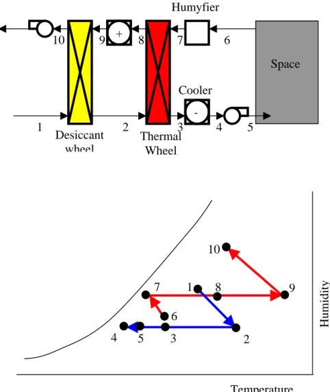
There are commercially available solid desiccant systems with typical COP values about 1, (Thompson, 1997). It can be found several solid desiccant materials, namely silica gel, carbon, etc. Fig.5 shows a typical solid desiccant system as well the psychometric chart of the air evolution.
In some cases the cooler (evaporator) mounted after the thermal wheel is replaced by an evaporative cooler in order to avoid the use of refrigerants. In this case there is an increase in humidity and a decrease in temperature after state 3.
Humyfier + -Space Desiccant wheel Thermal Cooler 10 9 8 7 6 1 2 3 4 5 Wheel 10 9 8 7 6 5 4 3 2 1 Humidity Temperature
Fig.5 – Solid desiccant system.
Typical values of the proprieties of the thermodynamic air states shown in figure 5 are represented in Table 1.
Table 1 – Typical thermodynamic properties of the air in a solid desiccant system.
State T [ºC] w [g/kg] State T [ºC] w [g/kg] 1 28 11 6 23 6.8 2 44.4 6.1 7 15.81 9.76 3 22.9 6.1 8 32.27 9.76 4 15 6.1 9 70 9.76 5 16.5 6.1 10 46 16
3.4.2. Liquid Desiccant systems
The working principles of these systems are similar to the solid desiccant systems only with differences in equipment. For example, in the liquid desiccant systems there is no desiccant wheel. Instead of it there are spray chambers. This is an advantage as usually the desiccant wheel has large diameters in order to better enable the heat and mass transfer, which turns this kind of equipment expensive.
Fig.6 shows a new liquid desiccant system where attention is due only to the differences regarding the conventional ones, (Oliveira, 2000).
Absorber Heat pipes Building
Evaporator Water
Water Heat exchanger
Desiccant solution Vapor Generator Heater Evapo- rator
Fig.6 – New liquid desiccant system.
In this new system the classical ventilators have been replaced by ventilators with rotors built with fibers which behave as evaporator or absorber, Fig. 7, enabling an increase in heat and mass transfer, (Afonso, 2000).
Fig.7 – Fiber rotor.
As liquid is injected in the center of the ventilators, flowing then over the fibers, there is also an effective removal of air particles promoting in that way the air cleaning.
The thermal wheel was also replaced by a more effective heat exchanger composed of heat pipes.
The absorbent used is lithium bromide. The potassium formate – HCOOK – is also under investigation as absorbent as it has a negative crystallization temperature being less corrosive and not as expansive as the others.
The COP varies with the internal and external air properties. Lower outside air temperatures and humidity gives higher COP values as can be seen in Fig. 8. These results were obtained for a relative humidity of 50% and a heat pipe efficiency of 70%, (Oliveira, 2000).
3.5. Ejector Systems
In this kind of systems it is possible to convert an available heat source in heating and cooling for buildings. 26 27 27 28 28 29 29 30 30 0,6 0,7 0,8 0,9 1,0 1,1 1,2 1,3 Tamb COP Ti=24ºC Ti=26ºC
Fig.8 – COP as a function of outside air temperature for two different indoor air temperatures.
The usual heat sources are the geothermal energy, solar energy, biomass or other kind of lost energy. As an example of this last one is the exhaust gases and the heat release from radiators of car engines that can be used for the acclimatization of vehicles.
A schematic diagram of this kind of systems is shown in Fig. 9. The boiler can be used as a complement to solar collectors, not shown in the figure.
When the application of this kind of systems is building air conditioning the most convenient heat source is the solar energy, (Holmes, 1979): it enables the summer cooling and the winter heating. And this is most interesting in commercial buildings where it is not necessary air conditioning in the evenings. This system is particularly interesting in places where there is no electrical energy and places where there are hot effluents.
BOILER EJECTOR HEAT EXCHANGER HEAT EXCHANGER EVAPORATOR CONDENSER
A new prototype of an ejector system was built with water in the secondary circuit (boiler and heat exchangers) and the n-pentane as working fluid in the primary circuit as it has as advantages good thermodynamic properties at relative low temperatures (about 85ºC) which enables that most of the heat supply to system to come from solar energy. Also, in opposition to the CFC’s the n-pentane is a green refrigerant, (Oliveira, 2001).
In this system the ejector replaces the compressor of the vapor compression system. The ejector has a venturi, a suction section, a converging section and a straight and diverting section, Fig. 10.
Fig.10 – View of an ejector.
This system has no moving parts, which turns them in very reliable systems. There are ejector systems operating for more than twenty years without any kind of problems.
With this prototype it is possible to have a global COP of 0.225 which with 50% of solar energy supply and 50% of heat release from a natural gas boiler can lower the cooling energy price to 0.019 €/kWh that is roughly half the price of a conventional system, (Afonso, 2001). Other ejector systems have been applied in several buildings with different kind of refrigerants and good results, (Wolpert, 2003; Wolpert, 2003).
4. HYBRID SYSTEMS
One kind of this system combines in a single cycle the vapor compression system and the absorption system, (Riffat, 1994), with the following advantages:
• Increase in COP values when compared with the absorption system. • Use of refrigerants of the absorption systems.
• Possibility of compression of the vapor flowing out of the generator and the use of it’s latent heat of condensation to reduce the necessary amount of thermal energy for the operation of the generator.
A hybrid system like this was built and it is shown schematically in Fig.11, (Riffat, 1996). As stated, the difference between this system and the absorption one lies on the generator where the necessary thermal energy for its operation comes out from the condensation of the refrigerant (process 2-3) that was previously released in the generator and compressed until a pressure such that the saturation temperature is above the one of the generator (process 1-2).
GENE-RATOR HEAT EXCHANGER ABSOR-BER EVAPORATOR H. SOURCE H.SINK H.SINK
Fig.11 – Hybrid system.
COP values of this systems lies between 2 and 3.5, (Afonso, 1995).
In order to intensify the several heat transfer processes in the system, application of centrifugal fields was done, (Afonso, 1995). In this case all heat and mass transfer equipment –evaporator, absorber, generator and condenser – were placed in a rotate ensemble, Fig.12.
Fig.12 – Hybrid system with a rotate ensemble – evaporator view.
5. CONCLUSIONS
In this report the main innovations in air conditioning systems have been presented. They are related with the research of new refrigerants environment friendly, with the development of new thermodynamic cycles namely the desiccants and hybrid and by the development of rotating devices to enhance the heat and mass transfer.
Some of these innovations are still in research, and in a short term they are about to substitute the conventional systems. The implementation of these new technologies will enable the
reduction the energy cost associated to the air conditioning, as well as the environment cost and in the initial cost of this kind of equipment.
The availability of these more efficient systems with lower costs will enable the diffusion of air conditioning systems in countries were they neither are nor spread.
The previsible decrease in dimension and costs of these new systems will have benefits in the increase of competitiveness of the air conditioning industry.
REFERENCES
Afonso, C.F.A.; Oliveira, A.C.F., Absorption-Recompression Cycle for Refrigeration Systems, Second International Thermal Energy Congress, ITEC 95, Agadir, Marrocos, 1995. Afonso, C.F.A.; Oliveira, A.C.F., Energetic Analysis of an Environment-Friendly Absorption-Compression Refrigeration Cycle, III International Congress on Energy, Environment and Technological Innovations, Caracas, Venezuela, 1995.
Afonso, C.; Oliveira, A., Ciclos Frigoríficos Dessicantes para o Condicionamento de Ar, 1º Congresso Luso-Moçambicano de Engenharia. Maputo, 1999.
Afonso, C.; Oliveira, A., Tecnologias Inovadores em Sistemas de Ar Condicionado, Climatization Journal, nº 8, year II, 2000.
Afonso, C.; Matos, J.; Oliveira, A., Sistema Híbrido para a Produção de Electricidade, Calor e Frio: Resultados Experimentais”. 1ª Jornadas Técnicas de Primavera da EFRIARC: Climatização & Refrigeração em Portugal, Porto, 2001.
Afonso, C.; Matos, J., The Effect of Radiation Shields in the Air Condenser and Compressor of Refrigerators on their Thermal Behavior, Paper submitted to the International Journal of Refrigeration”. 2004.
Bassols, J. et al., First Operation Results of a Gas-Fired 250 kW Absorption Heat Pump With Plate-Fin Heat Exchangers, International Absorption Heat Pump Conference. AES-vol.31.
ASME (1993).
Bol, B., A Novel Vapour Absorption Refrigeration/Heating System using a Membrane Separation Process, Ph.D. Thesis, Nottingham, 2002.
Bosnjakovic, F., Technical Thermodynamics, Holt, Rinehart and Winston, Inc. Edition, 1965. Çengel, Y.; Boles, M., Thermodynamics, McGraw-Hill Editions. 1994.
Gosney, W.B., Principles of Refrigeration, Cambridge University Press, 1982.
Holmes, R.; Jenkins, P., Design of Freon Jet Pump for Use in a Solar Cooling System, ASME Paper, nº78 WA/SOL – 15, 1979.
IEA, Energy technologies for reducing emissions of greenhouse gases, Proc. Seminar Paris. Kinsky, R., Applied Heat, McGraw-Hill Book Company, Sydney, 1977.
Oliveira, A; Afonso, C.; Riffat, S., Thermal Performance of a Novel Air Conditioning System Using a Liquid Dessicant, Applied Thermal Engineering, Vol. 20, Pergamon Press, 2000. Oliveira, A.; Afonso, C.; Riffat, S.; Doherty, P., Thermal Performance of a Novel Air Conditioning System using a Liquid Desiccant, Applied Thermal Engineering, Vol. 20, 1213-1223. 2000.
Oliveira, A. et al., A Combined Heat and Power System for Buildings Driven by Solar Energy and Gas, HPN-2001 Conference, CNAM, Paris, 2001.
P. D. Fairchild e W. Fulkerson, Energy Technology R&D and Greenhouse Effect, Saito, pp. 231-241, 1989.
Pettersen, J., Refrigerating, Air Conditioning and Heat Pump Systems Based on CO2, IEA
Annex 22 Workshop on Compression Systems With Natural Working Fluids, Trondheim,
Norway, 1995.
Règlement (CE) nº 2037/2000 du Parlement européen et du Conseil du 29 Juin 2000 relatif à des substances qui appauvrisent la couche de ozone.
Riffat, S.; Afonso, C.; Oliveira, A.; Reay, D., Natural Refrigerants for Refrigeration and Air Conditioning Systems”. Applied Thermal Engineering, 16, (1), (1997) 33-42.
Riffat, S.B.; Shankland, N.J.; Wong, C.W., Rotary Absorption-Recompression Heat Pump, Building Services Engineering Research Technology, 15 (1) (1994) 27-30.
Riffat, S.; Webb, R; Afonso, C.; Oliveira, A.; Sirén, K.; Karola, A., An Efficient Rotary Absorption Recompression Heat Pump for Air-Conditioning, Absorption Heat Pump Conference 96, CANMET, Montreal, 1996.
Smith, J.T., A Comparision of the CO2 Emission Rates of Gas-Fired and Electrically Driven Chiller/Heater Machines under Dynamic Loading, CIBSE National Conference, pp 151-159, Eastbourne, England, 1995.
Sonntag, R.; Borgnakke, C.; Wylen, G., Fundamentals of Thermodynamics, John Wiley&Sons, Inc. Edition, 1998.
Stoeker, W.; Jones, J., Refrigeration & Air Conditioning, McGraw-Hill International Editions, 1982.
Thompson, K., Technical Trends in Solar Cooling, Proceedings Seminar on Dessicant Cooling, CIBSE, 1997.
Warwicker, B., Low Humidity and Air Conditioning, CIBSE Journal, Technical File, 1995. Whitman, D.; Miriam, J. - “Gas Air Conditioning”. British Gas publ., External Report MRS E 648, 1991.
Wolpert, J.; Riffat, S., Recent Developments in Solar Cooling Systems, Institute of Building Technology, Internal Report, University of Nottingham, 2001.
Wolpert, J.; Riffat, S., Prototype for a Novel Solar Powered Ejector Air-conditioning System in Mazunte, Proceedings for the International Solar Energy Society Congress, Goteborg, Sweden, 2003.
Wolpert, J., Solar Powered Ejector Air Conditioning System for Mexican Climate, Ph.D. Thesis, Nottingham, 2003.