Faculdade de Ciˆencias
Departamento de Inform´atica
PESTT:
PESTT EDUCATIONAL SOFTWARE TESTING TOOL
Rui Manuel da Silveira Gameiro
PROJECTO
MESTRADO EM ENGENHARIA INFORM ´
ATICA
Especializac¸˜ao em Engenharia de Software
Faculdade de Ciˆencias
Departamento de Inform´atica
PESTT:
PESTT EDUCATIONAL SOFTWARE TESTING TOOL
Rui Manuel da Silveira Gameiro
PROJECTO
Projecto orientado pelo Prof. Doutor Francisco Cipriano da Cunha Martins
MESTRADO EM ENGENHARIA INFORM ´
ATICA
Especializac¸˜ao em Engenharia de Software
Agradec¸o em primeiro lugar ao meu orientador o Professor Doutor Francisco Mar-tins, pelo apoio, suporte e dedicac¸˜ao demonstrada durante este ´ultimo ano. Foi um pri-vil´egio e um grande prazer poder realizar este projecto juntamente com o Professor. Mais do que meu orientador, considero o Professor um verdadeiro amigo. Muito Obrigado Professor.
Um especial agradecimento tamb´em ao meu colega Jo˜ao Veiga, pelas informac¸˜oes fornecidas que foram fundamentais para que este projecto avanc¸asse, pelas conversas que tivemos durante os almoc¸os, essenciais n˜ao s´o para nos distrairmos, mas tamb´em para trocarmos ideias.
E o que seria de mim sem a minha fam´ılia? Queria portanto agradecer a quem mais fez por mim, aos meus pais e a minha irm˜a. Aos meus pais por me darem todas as condic¸˜oes e suporte necess´arios para eu ter conseguido chegar onde cheguei, pelos momentos que dediquei mais ao trabalho e menos a vocˆes, por me aturarem, pela vossa dedicac¸˜ao, pelo vosso apoio incondicional e, principalmente, pela vossa paciˆencia, o meu Muito Obrigado por tudo o que fizeram por mim. Obrigado tamb´em `a minha irm˜a, pelo apoio e pela ajuda que me deu nos momentos mais dif´ıceis.
Um obrigado ao resto da minha fam´ılia e amigos pelos bons momentos que pass´amos juntos.
Espero que o meu esforc¸o, dedicac¸˜ao, empenho e resultados tenham superado as vossas expetativas.
A sociedade em que vivemos ´e completamente dependente da tecnologia. Desde os simples equipamentos dom´esticos, como televisores, frigor´ıficos ou telefones, passando, por exemplo, pelos meios de transporte (e.g., autom´oveis, comboios, avi˜oes), todos eles contˆem software que ´e indispens´avel ao seu funcionamento, e que se falhar pode ter con-sequˆencias devastadoras, tanto em termos da nossa comodidade como em impacte finan-ceiro.
A ubiquidade e consequente criticidade do software requer que este possua um n´ıvel de qualidade elevado. ´E neste contexto que entram os testes de software, que consti-tuem um dos principais mecanismos para reduzir a ocorrˆencia de problemas e garantir a qualidade do software produzido.
Saber planear, desenhar e automatizar a execuc¸˜ao de testes ´e portanto uma valˆencia imprescind´ıvel ao engenheiro de software. A ferramenta que propomos—PESTT Educa-tional Software Testing Tool (PESTT)—vem auxiliar a atividades de desenho e de an´alise de cobertura de testes unit´arios baseados em grafos de controlo de fluxo (CFG).
A ferramenta inicialmente foi pensada para ser usada como suporte ao ensino dos conceitos e t´ecnicas introdut´orias de teste de software, mas pode tamb´em ser usada em outros cen´arios. O UI cuidadosamente pensado e a sua integrac¸˜ao flex´ıvel no Eclipse IDE, torna o PESTT um auxiliar valioso para professores e alunos.
Os conceitos de testes encontram-se bem organizados: uma vista para o CFG (auto-maticamente gerado a partir do c´odigo fonte Java), uma vista onde pode ser escolhido o crit´erio de cobertura estruturada de uma maneira que torna simples visualizar que crit´erio subsumeoutros, uma vista para gerir os requisitos de teste e a sua relac¸˜ao com o CFG e com o c´odigo fonte, uma vista para os caminhos de teste, uma outra para as estat´ısticas de cobertura e ainda uma vista para a informac¸˜ao relacionada com o fluxo de dados. Todas estas vistas encontram-se integradas umas com as outras de forma a poder disponibilizar a maior quantidade poss´ıvel de informac¸˜ao ao engenheiro de teste.
O PESTT encontra-se integrado com o JUnit e com o Byteman de forma a poder disponibilizar os caminhos executados (no CFG) pelos testes; disponibiliza tamb´em as estat´ısticas referentes a cada teste ou para o conjunto de testes, que permite que o enge-nheiro possa ter a percec¸˜ao dos n´ıveis de cobertura atuais (individual ou total) dos testes.
tras funcionalidades an´alise de cobertura baseada em CFG (que para al´em de incluir os crit´erios de cobertura de n´os e arestas) inclui outros mais poderosos e auxilia o engenheiro de testes no planeamento das v´arias atividades do processo de testes.
Este documento d´a a conhecer os aspetos relacionados com o PESTT, necess´arios para a sua concretizac¸˜ao, noemadamente, os conceitos te´oricos essenciais para a sua correta utilizac¸˜ao, as ferramentas de cobertura existentes e as respetivas contribuic¸˜oes para o PESTT, passando pela arquitetura, n˜ao esquec¸endo a implementac¸˜ao dos algoritmos dos crit´erios de cobertura baseados no CFG, fundamentais para obter os requisitos de teste, na obtenc¸˜ao dos caminhos de testes executados, entre outras funcionalidades.
Palavras-chave: PESTT, Plug-in, Eclipse, Teste de Software, Ensino.
The society we live in is completely dependent of technology. From simple home ap-pliances such as televisions, Refrigerators or telephones, passing, for example, by trans-ports (e.g., cars, trains, plains), they all contain software that is essential to its operation, and if it fails the consequences can be devastating, both in terms of our comfort as finan-cial impact.
The ubiquity and consequent criticism of Software requires that this have a high level of quality. It is in this context that enter the Software tests, which are a major mechanism for reducing the occurrence of problems and ensure the quality of the Software produced. Learn to plan, design and automate test execution is therefore a valence essential to the Software engineer. The tool we propose—PESTT Educational Software Testing Tool (PESTT)—comes to auxiliary the activities of design and coverage analysis of unit testing based on flow control graph (CFG).
PESTTstarted as a tool specially tailored for teaching how to test software, but can be very well used in other scenarios. Its suits well the teaching of software testing classes, because of its careful designed UI and its smoothly integration with the Eclipse IDE.
The testing concepts are well organized: a view for the control flow graph (automat-ically generated from the method’s source code), a view with the supported coverage criteria arranged in such a way that it is easy to visualize which criteria subsumes others, a view for manipulating test requirements and its explanation both in terms of the control flow graph and of the source code, a view for the test paths, another for coverage statistics, yet another for data flow information, and all these views integrated together to give as much information as possible to the test engineer.
It provides integration with JUnit and Byteman and reconstructs run paths of each test method, computing statistics either for each test method or for the complete test set, this allows the engineer to get the current levels of tests coverage (individual or total).
PESTT distinguishes from other coverage analysis testing tools because it is not just a node and branch coverage analyzer. Among other things, it supports many other more powerful coverage criteria and assists the test engineer in the various tasks of the testing activity.
This report aims at describing the aspects of PESTT, citing the necessary mechanisms for its implementation, in particular, theoretical concepts used essential for its correct use,
mental to obtain the test requirements or obtaining the executed paths of tests performed, among other features.
Keywords: PESTT, Plug-in, Eclipse, Software Testing, Education
List of Figures xiii
List of Tables xv
1 Introduction 1
2 The Basis of Software Testing 5
2.1 Fundamental Concepts . . . 5
2.2 Graphs. . . 7
2.2.1 Graph Concepts. . . 7
2.2.2 Graph Coverage Criteria . . . 8
2.2.2.1 Structural Coverage Criteria . . . 8
2.2.2.2 Data Flow Coverage Criteria . . . 10
3 Related Work 13 3.1 Visualization Tools . . . 13
3.2 Generators and Recognizers . . . 16
3.2.1 Generators . . . 16 3.2.2 Recognizers. . . 17 3.2.3 Instrumentation . . . 19 3.2.4 Contributions . . . 27 4 Architecture 29 4.1 Overview . . . 29 4.1.1 EclipseArchitecture . . . 29
4.2 Integration and Dependencies. . . 32
4.3 Internals . . . 33
4.3.1 CFG: Model and Representation . . . 35
4.3.2 Requirements Module . . . 37
4.3.3 Tests Module . . . 41
4.3.4 UI Module . . . 44 xi
5.1.1 The CFG Model . . . 51
5.1.2 CFG Model (Optimization) . . . 59
5.1.3 CFG Representation using Zest . . . 61
5.2 Graph Coverage . . . 62
5.2.1 Structural Coverage Criteria . . . 63
5.2.2 Data Flow Coverage Criteria . . . 71
5.2.3 Tour Types . . . 83
5.3 Test Path. . . 86
5.3.1 Test Path Generation . . . 86
5.3.2 Test Path Execution. . . 90
6 Evaluation 97 6.1 Evaluation Plan . . . 97
6.2 Conclusions of the Test Evaluation . . . 100
6.3 Users testimonials . . . 100
7 Conclusion 103 A Pseudocode snippets 105 A.1 List of rules . . . 105
A.2 MANIFEST.MF . . . 106
A.3 plugin.xml . . . 109
A.4 Graph Coverage Criteria View . . . 111
A.5 CFG Builder. . . 116
A.6 Users testimonials . . . 117
A.7 Users testimonials . . . 118
Bibliography 121
2.1 The subsumption relationship among graph coverage criteria . . . 12
3.1 Graph description in a simple text language for a given specification in Dot 14 3.2 The CFG for the specification shown in Figure 3.1a . . . 14
3.3 The CFG for Listing 3.1 . . . 22
4.1 The OSGi architecture [31] . . . 30
4.2 The Eclipse architecture [21] . . . 31
4.3 Simplified view of PESTT dependencies . . . 33
4.4 PESTTplug-in architecture overview. . . 34
4.5 PESTTplug-in architecture . . . 34
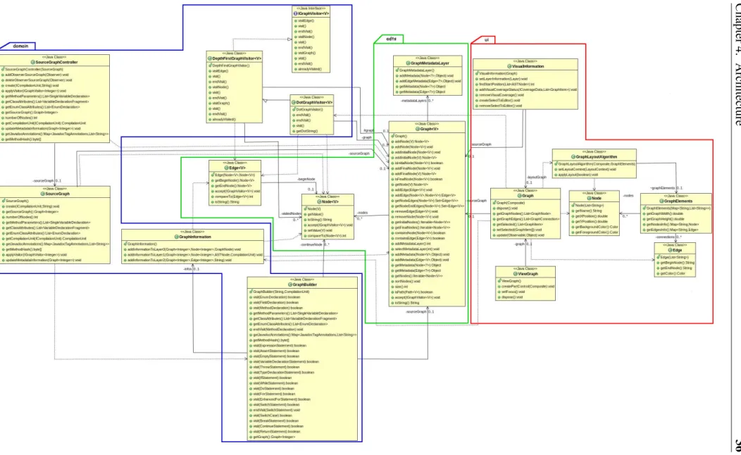
4.6 UML Class diagram for the CFG model and their representation . . . 36
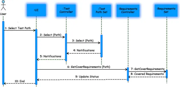
4.7 Sequence Diagram for test path selection. . . 38
4.8 Result of the test path selection . . . 39
4.9 UML Class diagram for the Requirements module . . . 40
4.10 UML Class diagram for the Tests module . . . 43
4.11 PESTT plug-in visual appearance. . . 44
4.12 UML Class diagram for the UI module . . . 50
5.1 The different representations of the CFG model during the build process . 60 5.2 CFG generated by Zest for the model pictured in Figure 5.1c . . . 62
3.1 Comparison of three types of instrumentation in Java (Clover [22]) . . . . 20
5.1 Definitions and uses for nodes and edges of Listing 3.1 . . . 80 5.2 Definitions and uses for the variables of Listing 3.1 . . . 80 A.1 The set of requirement paths generated to the prime path coverage
crite-rion for Listing 3.1 . . . 118
Introduction
Software Engineering is an area of Computer Science that uses a set of management pro-cesses, design activities, and software tools, whose goal is the development of software. The main focus of Software Engineering is to create good solutions for computing prob-lems and for information processing:
• with quality; • meeting deadlines;
• meeting the needs of customers and users;
through the application of systematic and disciplined approaches of development and maintenance. In other words, Software Engineering can be defined as a discipline that applies Engineering principles in order to produce quality software (the product).
In a society completely dependent on technology, from simple home appliances, such as televisions, telephones, and refrigerators, to, for example, transport system (e.g., cars, trains, planes), they all contain software, which is essential to its operation, and if it fails, the consequences can be devastating, both in terms of our comfort and of financial impact. The ubiquity and consequent criticality of software requires that it must have a high quality level. To ensure the final quality of the developed software, it is necessary to use different processes, techniques, methodologies, and tools in the various stages of the software development process. Is in this context that Software Testing appear, as one of the activities of the development process, whose purpose is to minimize the existence of software failures and to ensure the quality of the produced software.
Learn how to plan, design, and automate the execution of tests is therefore essen-tial to a software engineer, which needs to master the different techniques and concepts associated with software testing.
Currently, there are several tools available on the market in the Verification, Validation, and Testingarea, providing many features; usually they are paid and very complicated to handle. Free tools tend to provide less features than the commercial ones, generally offer only one specific type of test/validation, which make them very limited.
However, none of these tools was designed to be used in teaching Software Test-ing, where the techniques and basic concepts are teached. Is in this context that PESTT Educational Software Testing Tool (PESTT)appears. This thesis describes PESTT, its ar-chitecture and its internals, and try to highlight the benefits of using PESTT in teaching the techniques and concepts of Verification of Software Testing.
The present work was motivated by the following remarks:
• the increasingly importance of Software Testing in the present days;
• the benefits that the automatization of the test design and test analysis processes have in terms of time required and occurrence of errors;
• the impact in learning Software Testing techniques and concepts when using a tool specifically designed for teaching;
• the influence of the tool in the quality improvement of the produced software; • my interest in the Software Engineering area, especially in Software Testing. The objective of this project is the production of a software tool to support teaching, in particular, the introduction of basic concepts and of the different techniques of Software Testing. In order to develop a useful and easy to use tool, some requirements need to be met:
• determine the requirements for unit testing, based on methods written in the Java programming language;
• apply a coverage criterion selected by the user;
• make available an integrated interface with the Eclipse [14] IDE (Integrated Devel-opment Environment), to help plan and view the tests run or to performed.
The main contributions of the work described in this thesis comprise: (i) the implementation of the project basis through:
(a) a flexible integration in the Eclipse IDE;
(b) a flexible integration with Zest visualization tool; (c) a UI implementation.
(ii) the mapping of a method source code with a Control Flow Graph (CFG), and vice-versa;
(iii) the implementation of different types of operations on the CFG: (a) its optimization;
(b) adding additional information to it; (c) linking it with the source code.
(iv) the implementation of coverage criteria algorithms based on CFGs; (v) the generation of test requirements for a method;
(vi) a flexible integration with JUnit; (vii) a flexible integration with Byteman;
(viii) the presentation of visual coverage status information.
This work took place at the Large-Scale Informatics Systems Laboratory (LaSIGE-FCUL), a research unit of the Department of Informatics (DI) of the University of Lisbon, Faculty of Sciences. It was developed within the scope of the PESTT project, which follows the Software Testing guidelines by Paul Ammann and Jeff Offutt [30].
The remainder of this thesis is structured as follows. Chapter2reviews the basic un-derlying concepts behind PESTT. Chapter3presents some tools used during the course of this work and points related tools for Software Testing. Chapter4describes PESTT architecture and Chapter5the development details of PESTT. Chapter6present PESTT evaluation tests. Finally, Chapter7, concludes with remarks and insight for future devel-opments.
The Basis of Software Testing
This chapter introduces some fundamental concepts, like Test Requirement, Coverage, Coverage Criterion, Graph Coverage, Control Flow Graph (CFG) that are essential to a proper understanding of the project. The introduction of these concepts allow us to estab-lish a parallel between the theoretical concepts and the implemented features presented in the subsequent chapters.
2.1
Fundamental Concepts
There are some ill-defined terms occasionally used in testing, like “complete testing”, “exhaustive testing”, or “full coverage”. These terms are poorly defined because of a fundamental theoretical limitation of software, more specifically, because the number of potential inputs for most programs is so large.
This is where formal coverage criteria come in. Since we cannot test with all inputs, coverage criteria are used to decide which test inputs to use. The software testing commu-nity believes that effective use of coverage criteria makes it more likely that test engineers will find faults in a program and provides informal assurance that the software is of high quality and reliability. From a practical perspective, coverage criteria provide useful indi-cators for when to stop testing. In other words, we can define coverage criteria in terms of test requirements. The basic idea is that we want our set of test cases to enjoy various properties, each of which is provided by an individual test case.
Definition 2.1. Test Requirement: A test requirement is a specific element of a software artifact that a test case must satisfy or cover.
Test requirements usually come in sets and can be described with respect to a variety of software artifacts, including the source code, design components, specification modeling elements, or even descriptions of the input space. For this project we are interested only in the test requirements generated from source code; later in this thesis we explain how to generate them.
Definition 2.2. Test Case: A Test case is a set of conditions or variables under which a test engineer will determine whether an application or software system is working correctly or not.
Suppose now that we have a method with a simple if-then-else statement, and we want to cover all decisions. A decision leads to two test requirements, one where the guard evaluates to true, which executes the code in the if branch, and another when it evaluates to false, executing the else branch. Calling the method leads to exercise one of this test requirements. A coverage criterion is simply a recipe for generating test requirements in a systematic way.
Definition 2.3. Coverage Criterion: A coverage criterion is a rule or collection of rules that impose test requirements on a test set.
That is, the criterion describes the test requirements in a complete and unambiguous manner.
Test engineers need to know how good a collection of tests is. To do that it is necessary to compare test sets against a criterion in terms of coverage.
Definition 2.4. Coverage: Given a set of test requirements TR for a coverage criterion C, a test setT satisfies C if, and only if, for every test requirement tr in TR, at least one test t inT exists such that t satisfies tr.
Coverage is important for two reasons. First, it is sometimes expensive to satisfy a coverage criterion, so we want to compromise by trying to achieve a certain coverage level.
Definition 2.5. Coverage Level: Given a set of test requirements TR and a test set T, the coverage level is simply the ratio of the number of test requirements satisfied byT to the size of TR.
Second, and more importantly, some requirements cannot be satisfied, making the criterion not 100% satisfied. In this scenario makes all sense to drop unsatisfiable test requirements from TR.
Test requirements that cannot be satisfied are called infeasible. Formally, no test case values exist that meet the test requirements. Dead code is an example that results in infeasible test requirements because the statements cannot be reached. The detection of infeasible test requirements is formally undecidable for most coverage criteria, and even though some researchers have tried to find partial solutions, they have had only limited success. Thus, 100% coverage is impossible in practice.
Coverage criteria are often related to one another, and compared in terms of subsump-tion. The essence of subsumption is: satisfying one criterion guarantees that another one is satisfied.
Definition 2.6. Criteria Subsumption: A coverage criterion C1subsumesC2 if, and only if, every test set that satisfies criterionC1also satisfiesC2.
2.2
Graphs
This section starts out with a brief description of graph concepts. Then, continues with the introduction of the coverage criteria applied to graphs used in the project—the Graph Coverage Criteria.
2.2.1
Graph Concepts
Given an artifact under test, the idea is to obtain a graph abstraction of that artifact; in our case the artifact is the source code. The graph abstraction for source code maps code to a Control Flow Graph (CFG). A CFG is a representation, using graph notation, of all paths that might be traversed through a program during its execution. It is important to understand that the graph is not the same as the artifact, and that, indeed, artifacts typically have several useful, but nonetheless quite different, graph abstractions. The same abstraction that produces the graph from the artifact also maps test cases for the artifact to paths in the graph. Formally, a graph is:
• a set N of nodes.
• a set N0 of initial nodes, where N0 ⊆ N . • a set Nf of final nodes, where Nf ⊆ N .
• a set E of edges, where E is a subset of N × N .
Edges are considered to be from one node to another and are written as (ni, nj) (di-rected edge).
Another important term is path. A path is a sequence of nodes ([n1, n2, ..., nM]), where each pair of adjacent nodes (ni, ni+1), 1 ≤ i < M, is in the set E of edges. Asso-ciated with path is the notion of length. The length of a path is defined as the number of edges it contains. A subpath of a path p is a subsequence of p (possibly p itself). Like in the edges, we can say that a path is from the first node in the path to the last node in the path. We can also say that a path is from (or to) an edge e, which simply means that e is the first (or the last) edge in the path.
A graph has to contain at least one node in N , N0, and Nf in order to be useful for generating tests.
Finally, we introduce the term test path. A test path represents the execution of a test case. A path p, possibly of length zero, that starts at some node in N0 and ends at some node in Nf.
The reason for the test path to start at some node in N0and to end at some node in Nf is that the execution of a test case always starts at an initial node and ends at a final node.
2.2.2
Graph Coverage Criteria
This section illustrates the different types of coverage criteria based on graphs. Coverage criteria may be divided in two types:
• Structural Coverage Criteria; • Data Flow Coverage Criteria.
We proceed by identifying the appropriate test requirements and then define each crite-rion in terms of the test requirements. In general, for any graph-based coverage critecrite-rion, the idea is to identify the test requirements in terms of various structures in the graph. For graphs, coverage criteria define test requirements, TR, in terms of the properties of test paths in a graph G. A typical test requirement is met by visiting a particular node or edge or by touring a particular path.
Definition 2.7. Visit: A test path p is said to visit node n if n is in p. In the same way, test pathp is said to visit edge e if e is in p.
The term visit applies well to single nodes and edges, but sometimes we want to turn our attention to subpaths. For subpaths, we use the term tour.
Definition 2.8. Tour: A test path p is said to tour subpath q if q is a subpath of p. The notion of tour requires more development. We return to the issue of touring later in this section and then refine it further in the context of data flow criteria.
To introduce the graph coverage criteria, we need to adequate the notion of Coverage (see Definition2.4). The following definition is a refinement of that definition:
Definition 2.9. Graph Coverage: Given a set TR of test requirements for a graph cri-terionC, a test set T satisfies C on graph G if, and only if, for every test requirement tr inTR, there is at least one test path p in T such that p cover tr.
This is a very general statement that must be refined for individual cases. 2.2.2.1 Structural Coverage Criteria
We start by defining criteria to visit every node and then every edge in a graph. The requirements that are produced by a graph criterion are technically predicates that can have either the value true (the requirement has been met) or false (the requirement has not been met). For Node Coverage, we must satisfy a predicate for each node, where the predicate asks whether the node has been visited or not. Similarly, for Edge Coverage, a predicate must be satisfied for each edge, where the predicate asks whether the edge has been visited or not. Formally we have:
Criterion 2.2. Edge Coverage (EC): TR contains each reachable path of length up to 1, inclusive, inG.
The test requirements for edge coverage also explicitly include the test requirements for node coverage, that is why the phrase “up to” is included in the definition. In fact, all the graph coverage criteria are developed like this. The motivation is subsumption for graphs that do not contain more complex structures.
Other coverage criteria that use only the graph definitions introduced so far, is Edge-Pair Coverage
Criterion 2.3. Edge-Pair Coverage (EPC): TR contains each reachable path of length up to 2, inclusive, inG.
Clearly, this idea can be extended to paths of any length, although possibly with di-minishing returns. With this context, Node Coverage could be redefined to contain each path of length zero, and Edge Coverage could be redefined to contain each path of length up to one.
To introduce the next criterion we need a few more definitions. We start with that of simple path:
Definition 2.10. Simple Path: A path from ni tonj is simple if no node appears more than once in the path, with the exception that the first and last nodes may be identical.
In other words, a simple path have no internal loops, although the entire path itself may wind up being a loop. One useful aspect of simple paths is that any path can be created by composing simple paths. For a coverage criterion for simple paths we would like to avoid enumerating the entire set of simple paths. Since most of the simple paths are subpaths of other simple paths, only maximal length simple paths are considered. Formally:
Definition 2.11. Prime Path: A path from ni tonj is a prime path if it is a simple path and it does not appear as a proper subpath of any other simple path.
Criterion 2.4. Prime Path Coverage (PPC): TR contains each prime path in G.
Prime Path Coveragehas two special cases. Both special cases involve the treatment of loops with “round trips”. A round trip path is a prime path of nonzero length that starts and ends at the same node. One type of round trip test coverage requires at least one round trip path to be taken for each node, and another requires all possible round trip paths. Criterion 2.5. Simple Round Trip Coverage (SRTC): TR contains at least one round-trip path for each reachable node inG that begins and ends a round-trip path.
Criterion 2.6. Complete Round Trip Coverage (CRTC): TR contains all round-trip paths for each reachable node inG.
Next we turn to path coverage.
Criterion 2.7. Complete Path Coverage (CPC): TR contains all paths in G.
Complete Path Coverageis not feasible for graphs with cycles, since this results in an infinite number of paths, and hence an infinite number of test requirements.
Touring, Sidetrips, and Detours
We previously defined “visits” and “tours” (see Definitions 2.7 and 2.8). Recall that using a path p to tour a subpath [n1, n2, ..., nM] means that the subpath is a subpath of p. This is a rather strict, because each node and edge in the subpath must be visited exactly in the order that they appear in the subpath. In order to include loops in a tour we can derive the tour definition in two ways:
The first allows the tour to include “sidetrips”, where we can leave the path temporar-ily from a node and then return to the same node.
Definition 2.12. Tour with Sidetrips: Test path p is said to tour subpath q with sidetrips if, and only if, every edge inq is also in p in the same order.
The second allows the tour to include more general “detours”, where we can leave the path from a node and then return to a forthcoming node on the path (skipping at least one edge).
Definition 2.13. Tour with Detours: A test path p is said to tour subpath q with detours if, and only if, every node inq is also in p in the same order.
In the above definitions, q is a required subpath that is assumed to be simple. 2.2.2.2 Data Flow Coverage Criteria
The next few testing criteria are based on the assumption that to test a program adequately, we should focus on the flows of data values. Specifically, we should try to ensure that the values created at one point in the program are used correctly. This is done by focusing on definitionsand uses of values. A definition (def) is a location where a value for a variable is stored into memory (assignment, input, etc.). A use is a location where a variable’s value is accessed. Data flow testing criteria use the fact that values are carried from defs to uses (du-pairs). The idea of data flow criteria is to exercise du-pairs in various ways.
First, we must integrate data flow into the existing graph model. Let V be a set of variables that are associated with the program artifact being modeled in the graph. Each node n and edge e is considered to define a subset of V; this set is called def(n) or def(e). Each node n and edge e is also considered to use a subset of V; this set is called use(n) or use(e).
Before entering the remaining criteria it is necessary to introduce the concept of def-clear. A path from location li to a location lj is def-clear with respect to variable v if for every node nk and every edge ek on the path, k 6= i and k 6= j, v is not in def(nk)or in def(ek). That is, no location between li and lj changes the value. If a def-clear path goes from li to lj with respect to v, we say that the def of v at lireaches the use at lj. In other words, the variable’s value is not changed by another def before it reaches the use.
Another important concept is du-path. A du-path with respect to a variable v is a simple paththat is def-clear with respect to v from a node ni, for which v is in def(ni), to a node nj, for which v is in use(nj).
The test criteria for data flow are defined as sets of du-paths. This makes the criteria quite simple, but first we need to categorize the du-paths into two groups.
The first grouping of du-paths is according to definitions. Let the def-path set du(ni, v) be the set of du-paths with respect to variable v that start at node ni. In other words, all du-paths with respect to a given variable defined in a given node.
The second, and more important, grouping of du-paths is according to pairs of defini-tions and uses. This is call def-pair. Let the def-pair set du(ni,nj, v)be the set of du-paths with respect to variable v that start at node ni and end at node nj. In other words, all du-paths with respect to a given variable that are defined in one node and used in another (possibly identical) node.
At this point we have the necessary information to present the remaining criteria: • All-Defs criterion;
• All-Uses criterion; and • All-du-Paths criterion.
All-Defs criterionrequires that each def reaches at least one use. The All-Uses cri-terion requires that each def reaches all possible uses. Finally, All-du-Paths criterion requires that each def reaches all possible uses through all possible du-paths. In a formal way:
Criterion 2.8. All-Defs Coverage (ADC): For each def-path set S = du(n, v), TR contains at least one path d inS.
Criterion 2.9. All-Uses Coverage (AUC): For each def-pair set S = du(ni, nj, v), TR contains at least one path d inS.
Criterion 2.10. All-du-Paths Coverage (ADUPC): For each def-pair set S = du(ni,nj, v), TR contains every path d in S.
Closing the chapter, Figure2.1shows the subsumption relationship among graph cov-erage criteria.
Related Work
There is many available literature that introduces the basic concepts and techniques of SoftwareTesting (e.g. [5, 24, 30]), however, there are no tools that support the teaching (and therefore learning) of these techniques and concepts in a comprehensive and inte-grated way. This chapter presents the related work in the area, indicating some tools and their contributions to this project.
3.1
Visualization Tools
The CFG is a key part in the introduction of software testing concepts. It is therefore essential to provide a good visualization mechanism of the CFG. In this section we present some visualization tools that were tried in the project, as well as a tool that fulfills our requirements.
Graphviz
Graphviz [20] is an open source graph visualization software. This tool allows us to represent structural information as diagrams of abstract graphs. To do it Graphviz uses many different kinds of languages (depending on the chosen algorithm), such as: Dot, Fdp, Neato, Twopi, Circo.
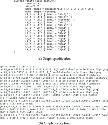
The method of operation is relatively simple: Graphviz receives a graph specifica-tion and produces a graph descripspecifica-tion in a simple text language. In order to generate the graph description, Graphviz requires a graph specification written in one of its supported languages—in our case the Dot language, because we want a directed graph. The graph specification (Figure3.1a) contains the information about the graph (initial nodes, final nodes, edges, color of nodes, etc), whereas the graph description, in addition to the in-formation provided by the specification, also indicates the exact position of each element (Figure3.1b).
The Graphviz layout programs take the graphs descriptions (in a simple text language), and make diagrams in useful formats, such as images and SVG for web pages, PDF or
(a) Graph specification.
(b) Graph description.
Figure 3.1: Graph description in a simple text language for a given specification in Dot
Postscript for inclusion in other documents; or display in an interactive graph browser. Also, Graphviz has many useful features for concrete diagrams, such as options for colors, fonts, tabular node layouts, line styles, hyperlinks, rolland custom shapes.
The Figure3.2shows a CFG obtained with Graphviz.
Figure 3.2: The CFG for the specification shown in Figure3.1a
This tool was an obvious choice to be integrate in this project for the following rea-sons:
• allows for drawing high quality CFGs (intersections rarely occur); • the amount and variety of available options;
• open source tool—its license allows the inclusion in a third party software with non-commercial purposes.
Zest
Although Graphviz is an excellent tool, it does not offer the required integration with Eclipseneeded for the project, in other words, the CFGs produced by Graphviz are static and do not allow any type of interactivity in Eclipse making them useless directly.
Fortunately, we found a tool that may be used to integrate Graphviz in Eclipse, Zest [37]. Zestis a visualization toolkit plug-in for Eclipse that has been developed in SWT/Draw2D and integrates seamlessly within Eclipse because of its recognized design. It has a pre-defined set of classes, interfaces, and operations to help building graphics on a Graphical Editing Framework (GEF)[18] editor. It has drag and drop support for its elements, uses animations when the graph is being drawn, and, mainly, allows an easy interaction be-tween the graph and the remaining elements of Eclipse. Zest also offers some default layout algorithms; namely:
• Spring Layout Algorithm; • Fade Layout Algorithm; • Tree Layout Algorithm; • Radial Layout Algorithm; • Grid Layout Algorithm.
However, Zest presents some limitations, the most significant are: none of the de-fault algorithms are powerful enough to display a CFG, and the visual appearance of the displayed graph is far from acceptable. These constraints mean that for the same graph specification Zest and Graphviz generate two very different graphs. In the project these limitations have a significant impact, since a good graph representation is essential.
To build the CFG, we implemented a new layout algorithm for Zest that integrates the graph produced by Graphviz into Zest, which we explain in detail in Section5.1.3. Eclipse Control Flow Graph Generation
The Eclipse Control Flow Graph Generation [19] is a plug-in for Eclipse that generates control flow graphs for Java code. Internally, it uses a graph model based on a toolkit called Java Development Toolkit (JDT) to handle operations with Java code. To do so, they traverse an Abstract Syntax Tree (AST) created by JDT using a visitor (ASTVisitor), associating each Java statement to a node in the graph model. Internally, they modified the Zest tree algorithm to display the graph model, as a CFG. For coverage purpose, this tool interacts with CodeCover [9] plug-in for Eclipse that we detail in Section3.2.2.
Although it generates the graphs based on the evaluation of the source code and pro-vides some coverage information with the help of CodeCover, Eclipse Control Flow Graph Generationdoes not meet our needs because:
• the generated CFG is not suitable for applying the coverage criteria specified in Section2.2.2;
• user interaction is very limited, as well as the information available;
• third party dependency for coverage, making limited the available coverage criteria. Its expansion would make the process too complex, further increasing the depen-dency.
3.2
Generators and Recognizers
In practical terms, we have two types of commercial automated testing tools generators and recognizers. A generator corresponds to a tool that automatically creates test case values; a recognizer is a coverage analysis tool. There is also a third group containing the tools that automatically create test scripts, however, this group of tools will not be addressed in this thesis, because the automatic creation of test scripts is not part of our goals.
Some of the available generators are “part” of xUnit. xUnit is the generic name by which the various code-driven testing frameworks are collectively known. These frame-works allow testing of different elements (units) of software, such as methods and classes. The main advantage of xUnit frameworks is that they provide an automated solution with no need to write the same tests many times, and no need to remember what should be the result of each test. Such frameworks are based on a design made by Kent Beck [4], originally implemented for Smalltalk [34] as SUnit [35].
Generator and recognizer tools are quite plentiful, both as commercial products and freeware.
3.2.1
Generators
Some of the most popular generators for Java language are:
JUnit
JUnit [26] is an open source unit testing framework that has been designed by Erich Gamma[16] and Kent Beck (ported from SUnit) for the purpose of writing and running tests in the Java programming language. It was the base of the xUnit architecture for unit testing frameworks that has been used in many programming languages, such as C, C#, and PHP, giving rise to various unit testing tools.
There are many ways to write test cases. A test case defines the tuple of input values, the expected values, and other information needed. These test cases need to be converted into executable fragments—test script. A test script is a test automation program code written in a programming language that checks that another code unit works as expected. So, if we want an accurate and efficient testing process, then using a good testing frame-work is recommended. JUnit has established a good reputation in this scenario.
Using a framework, like JUnit, to develop test cases has a number of advantages, the most important being that others are able to understand test cases, write new ones, and that most development tools enable for automated or one click test case execution.
JUnitalso provides a graphical user interface (GUI)–only in frameworks like Eclipse– that makes it possible to write and test source code quickly and easily. JUnit shows test progress in a bar that is green if testing are going fine and it turns red when a test fails. There is a lot of pleasure in seeing the green bar growing in the GUI output. A list of unsuccessful tests appears at the bottom of the display window. We can run multiple tests concurrently. The simplicity of JUnit makes it possible for the software developer to correct bugs as they are found.
TestNG
TestNG[36] is a general purpose open source unit testing framework inspired from JUnit and NUnit [29], but introducing some new functionalities in order to make it more pow-erful and easier to use. TestNG is available for Eclipse as a plug-in and is also one of the xUnitframeworks. Some of the features offered by TestNG are: flexible test configura-tion, support for data-driven testing (with @DataProvider), support for multiple instances of the same test class (with @Factory), support for parameters, allows for distribution of tests on worker machines, and allows for generation of test reports in HTML and XML formats.
3.2.2
Recognizers
Most recognizers interact internally with a generator in order to function properly. In other words, recognizers use generators to provide coverage information about executed test cases. Some of the most popular recognizers for the Java language are:
Jtest
Jtest[25] is a commercial integrated solution for automating a broad range of practices proven to improve development team productivity and software quality. It focuses on practices for validating Java code and applications. Jtest is one of the xUnit frameworks, meaning that it can be considered also as a generator. Jtest facilitates unit testing, static analysis, peer code review, and runtime error detection.
As Jtest, PESTT also perform code static analysis, however, in PESTT peer code review and runtime error detection are not supported, as it is not part of our immediate goals. Likewise, PESTT offers CFG visualization and additional coverage criteria not available in Jtest.
Google CodePro Analytix
Google CodePro Analytix [1] is an open source coverage analysis tool. However, this tool is much more complete than the other coverage analysis tools, because it offers many features, such as code analysis, many different types of metrics, JUnit test generation, JUnittest editor, code coverage, dependency analysis, similar code analysis, and Javadoc maintenance.
Google CodePro Analytix is the premier Java software testing tool for Eclipse de-velopers who are concerned about improving software quality and reducing development costs and schedules. It provides some of the features that are also available in by PESTT, such as code coverage and some of the metrics. However, in code coverage PESTT pro-vides a larger number of criteria, beyond the coverage criteria based on nodes and edges available in Google CodePro Analytix. It also provides automatically JUnit test gen-eration, dependency analysis, similar code analysis, and Javadoc maintenance, features that are outside the scope of PESTT. About teaching software testing techniques, Google CodePro Analytixis not very useful, since the features offered are geared for those who already know what to test and how to do so, and not for beginners.
Clover
Clover[7] provides metrics for better balancing the effort between writing code that does stuff and code that tests stuff. Clover runs in Eclipse and IntelliJ IDE or in continuous integration system, and includes test optimization to make tests run faster and fail more quickly. Clover is a commercial product, but it is freely available to open source projects and non-profit institutions. Some of the features available are: color-based visual annota-tion of test coverage, line-by-line test coverage info in source files, pass/fail informaannota-tion for recent test runs.
As Clover, PESTT also include color-based visual annotation of test coverage and line-by-line test coverage info in source files. PESTT does not perform any task regard-ing test writregard-ing or test execution; this is done internally by JUnit. Clover has its own mechanisms for test optimization and test runs.
codeCover
codeCoveris a free glass-box testing tool. codeCover measures statement, branch, loop, and term coverage (subsumes Modified Condition/Decision Coverage (MC/DC)),
ques-tion mark operator coverage, and synchronized coverage (used to synchronize critical code sections. If a synchronized statement is locked, other threads will wait until the locked section is set free. The synchronized coverage metric shows whether a synchro-nize statement has caused waiting effects.). It allows report creation (and customization) in HTML. codeCover can be integrated in Eclipse, Batch, and Ant. It also provides color-based visual annotation of test coverage, line-by-line test coverage info in source files, pass/fail information for recent test runs, and coverage statistics.
codeCoverprovides features that are not supported by PESTT, such as: term coverage, synchronized coverage, or report generation. Likewise, PESTT provides a CFG relative to the source code and some other coverage criteria like Prime path coverage, All-du paths coverage, etc.
EclEmma
EclEmma [12] is an open source Eclipse plug-in based on JaCoCo [23], inspired in Emma[13]. It uses the information generated from JUnit test run. EclEmma offers fea-tures like coverage overview details, source code highlighting, different types of metrics (instructions, branches, lines, methods, types, or cyclomatic complexity), multiple cov-erage sessions, merge sessions, and import/export features (execution data import and coverage report export).
PESTT provides most of the features available in EclEmma, coverage overview de-tails, source code highlighting, different types of metrics (instructions, branches, lines, methods, types or cyclomatic complexity), besides more coverage criteria and a CFG viewer. In the other hand, PESTT do not offer report generation or operations over ses-sions, which are provided by EclEmma.
There are many other coverage analysis tools for the Java programming language like Cobertura[8], DevPartner [11] and JMockit Coverage [10], but any of them does what we propose.
3.2.3
Instrumentation
An important concept related to coverage analyzers is code instrumentation. Coverage analyzers work by adding information to the original source code—code instrumentation. For Java, coverage analyzers fall into three categories:
• those that run the code in a modified Java Virtual Machine (JVM); • those that add instrumentation to the Java bytecode; and
• those that insert instrumentation into the Java source code.
The following table compares the different methods of obtaining code coverage and their relative benefits:
Possible Features JVM Bytecode Source code Can work without source yes yes no
Compilation time no impact variable variable
Container friendly no no yes
Control which entities are
reported on limited limited yes Gathers branch coverage indirectly indirectly yes Gathers method coverage yes yes yes Gathers source metrics no no yes Gathers statement coverage line only indirectly yes Requires separate build no no yes Requires specialized runtime yes yes no
Runtime performance high impact variable variable Source level directives to
control coverage gathering no no yes View coverage data in-line
with source not accurate not accurate yes Table 3.1: Comparison of three types of instrumentation in Java (Clover [22])
We chose to add instrumentation directly to the bytecode, because we feel this is the best approach, since it does not require a modified VM, but still retains a big speed advantage over having to compile all the source code twice.
Next, we present two tools that instrument the Java bytecode: JaCoCo and Byte-man[6].
JaCoCo
JaCoCo is a free Java code coverage library distributed under the Eclipse Public Li-cense[27]. The JaCoCo mission is to become the standard backend technology for code coverage analysis in JVM based environments. Their focus is on providing a lightweight, flexible and well-documented library for integration with various build and development tools.
JaCoCouses a set of different counters to compute coverage metrics. All these coun-ters are derived from information contained in Java class files, which basically are Java bytecode instructions and debug information optionally embedded in class files. JaCoCo provides the following metrics: instructions coverage, branches coverage, cyclomatic complexity, line coverage, method coverage, and classes coverage.
To provide the above features, coverage information has to be collected at runtime. For this purpose JaCoCo creates instrumented versions of the original class definitions. The instrumentation process happens on-the-fly during class loading using Java agents. The Java agents are loaded by the application class loader, therefore, the classes of the
agent live in the same name space as the application classes. The JaCoCo build, moves all agent classes into a unique package. Instrumentation requires mechanisms to modify and generate Java bytecode. JaCoCo uses the ASM [3] library for this purpose, internally. The strategy used by JaCoCo for instrumentation is to insert probes into the control flow at runtime and analyze the actual code coverage. Probes are additional instructions that can be inserted between existing instructions. They do not change the original behav-ior of the method, but record the fact that they have been executed. JaCoCo implements probes with abooleanarray instance per class. Each probe corresponds to am entry in this array. Whenever the probe is executed, the entry is set to true. With this strategy it knows exactly the nodes that were executed.
Now, we illustrate the JaCoCo mode of operation, through a simple example, based on the following method:
1 public class DemoClass { 2
3 public void demo() {
4 for(int x = 0; x <= 3; x++) { 5 if(x % 2 == 0) 6 System.out.println("even"); 7 else 8 System.out.println("odd"); 9 if(x >= 2)
10 System.out.println("greater or equal than 2"); 11 else
12 System.out.println("less than 2"); 13 }
14 } 15 }
Listing 3.1: Method used to explain the operation of JaCoCo and Byteman. The previous method is extremely simple: a variablex varies between [0..3], and each loop iteration verifies if the current value of x is even or odd (the first if-else block) and, after, if x is greater or equal than 2 (the second if-else block). The goal is to illustrate the anal-isys of the so called double diamond construction. This example uses a double diamond inside a for loop, in order to make it slightly more interesting. For a better understanding of the method, Figure3.3 shows the corresponding CFG. The correspondence between the nodes of the CFG and the method is done as follows:
• Node 0 -int x = 0;
• Node 1 - the begin offorstatement;
• Node 2 - does not have any instruction (corresponds to an implicitreturn); • Node 3 - the begin of the firstifstatement;
• Node 4 -System.out.println("even"); • Node 5 - the begin of the secondifstatement;
• Node 6 -System.out.println("greater or equal than 2"); • Node 7 -x++;
• Node 8 -System.out.println("less than 2"); • Node 9 -System.out.println("odd");
Figure 3.3: The CFG for Listing3.1 To test our example we use the following test script:
1 public class TestDemoClass {
2
3 @Test
4 public void testDemo() {
5 DemoClass dc = new DemoClass(); 6 dc.demo();
7 } 8 }
Listing 3.2: A test for the method shown in Listing3.1
As a probe implementation itself requires multiple bytecode instructions this would increase the size of the class files and slowdown execution speed of the instrumented classes. In order to reduce these risks, JaCoCo uses a few number of probes, inserting them in particular places. It inserts probes at every:
• method exit (return or throws);
If a probe has been executed, JaCoCo knows that the corresponding edge has been visited. From this edge it can infer about other preceding nodes and edges that:
• if an edge has been visited, it knows that the source node of this edge has been executed;
• if a node has been executed and the node is the target of only one edge it knows that this edge has been visited.
The blue marks shown in the Figure 3.3 illustrates the places where the probes are inserted by JaCoCo to instrument the method shown in Listing 3.1. With this probes JaCoCocan collect the necessary information to generate node and edge coverage.
When running the test (Listing3.2) JaCoCo starts with abooleanarray of size seven with its elements set to false. As Figure 3.3 shows each probe has a number that cor-responds to the index in the array. In the first loop iteration probes 0, 1, 4, and 5 are executed, setting the corresponding array elements to true. The second iteration executes probes 2, 4, and 5. Probes 4 and 5 were already executed in loop’s first iteration, so the values in the array for these elements are already set to true. The third loop iteration ex-ecutes probes 1, 3, and 5, which only sets the array elements corresponding to probe 3 to true. The fourth loop iteration executes probes 2, 3, and 5. The array does not change be-cause these elements are already set. When the method exits probe 6 is executed, setting the corresponding array element to true.
At the end of the method execution all array elements are true. With this information JaCoCo guesses node and edge coverage. To compute the final node coverage result JaCoConeeds to interpret the collected information. Probe 0 visited the edge (0, 1) so it executes nodes 0 and 1. Probe 1 visited edge (4, 5), meaning that nodes 4 and 5 are executed. As we indicated above, if a node has been executed and it is the target of only one edge, JaCoCo infers that this edge has been visited, which means that edge (3, 4) is visited and so node 3 is executed. Applying this rule to probes 2, 3, and 4, it concludes that nodes 6, 7, 8, and 9 are also executed (excluding those already executed). Probe 5 does not add new nodes to the list of executed nodes (probe 5 visits edge (7, 1), meaning nodes 1 and 7 executes). Finally, probe 6 indicates the execution of node 2. As final result we get that all nodes are covered. With only the information stored in theboolean array, JaCoCo cannot determined Edge-pair coverage, Prime Path coverage etc. Since it requires to know if an edge is visited after another edge has been visited just before. Byteman
Bytemanis a tool that simplifies tracing and testing of Java programs. Byteman allows us to insert extra Java code into an application, either as it is loaded during JVM startup or even after it has already started running. The injected code is allowed to access any appli-cation’s data and call any appliappli-cation’s method. We can inject code almost anywhere and
there is no need to prepare the original source code in advance, nor the need to recompile, repackage, or redeploy the application. In fact, we can remove injected code and reinstall different code while the application continues to execute.
Bytemanworks by modifying the bytecode of the application classes at runtime. Since it only needs access to bytecode, this means it can modify library code whose source is either unavailable or unable to be recompiled.
Bytemanuses a clear, simple scripting language, based on a formalism called Event Condition Action (ECA)rules to specify where, when, and how the original Java code should be transformed. An event specifies a trigger point, a location where we want code to be injected. When execution reaches the trigger point, the rule’s condition, a Java boolean expression, is evaluated. The Java expression (or sequence of expressions) in the rule action is executed only when the condition evaluates to true. Normally, execution continues from the trigger point once the injected code has been executed. However, rule actions may also throw an exception or force an early return from the triggering method.
Now, we illustrate the Byteman mode of operation, through a simple example, based on the method shown in3.1.
The first thing to do is to define the rules to be used; so, we need to specify where, when, and how the original Java code should be transformed. We do not want to change the original Java code, just need to be notified when a CFG node is executed. The simplest approach would be to define a rule for each CFG node. We know that one node is executed if the program executes the first instruction associated with it, so placing a trigger point at the line of the first instruction of each node allows us to know if the node is executed (depending on whether the rule is executed or not). Listing3.3shows the rules to get node coverage through Byteman.
1 RULE r2 2 CLASS DemoClass 3 METHOD demo 4 AT LINE 4 5 IF true 6 DO System.out.println("1 7") 7 ENDRULE 8 9 RULE r3 10 CLASS DemoClass 11 METHOD demo 12 AT LINE 5 13 IF true 14 DO System.out.println("3") 15 ENDRULE 16 17 RULE r4 18 CLASS DemoClass 19 METHOD demo
20 AT LINE 6 21 IF true
22 DO System.out.println("4") 23 ENDRULE
Listing 3.3: Rules to get node coverage through Byteman. The entire list of rules can be seen in AppendixA(SectionA.1).
Each rule is defined by a set of elements:1
• RULE - the name of the rule (must be unique or Byteman will only run the last rule with this name); also indicates the beginning of a new rule;
• CLASS - the name of the class where the rule will be inserted; • METHOD - the name of the method where the rule will be inserted; • AT LINE - the line number where the rule will be inserted;
• IF - the evaluation condition;
• DO - the code to be executed if the condition evaluates to true; • ENDRULE - indicates the end of the rule.
Of the elements listed above the only one which is not required is AT LINE, all the others are part of any rule definition. In this case the use of AT LINE makes all sense, because we know, if the program executes an instruction in a particular line, and this line has associated a trigger point, then we are sure that the node will be executed (the reason why the evaluation condition is just true). Since the evaluation condition is true, every time a trigger point is reached, the condition is executed, in other words, the number of the node is printed.
As we did for JaCoCo, we illustrate Byteman’s mode of operation to get node cover-age. Running the test shown in Listing3.2generates the following output:
1 0 2 1 7 3 3 4 4 5 pair 6 5 7 8 8 less than 2 9 3 10 9 11 odd 12 5 13 8 14 less than 2 15 3 16 4
17 pair 18 5 19 6
20 greater or equal than 2 21 3
22 9 23 odd 24 5 25 6
26 greater or equal than 2 27 2
Listing 3.4: Output generated by running the test (Listing3.2) with the Byteman rules. The output generated may seem a little strange at first glance. Probably, the reader would expect more lines with 1 7 (at least one for each loop iteration). The truth is that the rule is trigger just before reaching the beginning of the loop. For a better understanding, look for the black marks shown in Figure3.3. Each rule is placed on the node’s extremity (immediately before executing the first instruction of the node). Let us clarify this situa-tion by going through the output. Once the test invokes the method, rule r1 is executed, printing 0. As the program execution is sequential, rule r2 is executed, printing 1 7. Then, prints 3 and 4 (the result of executing rules r3 and r4) and “even” (by executingSystem .out.println("even")). This happens because rule r4 is triggered just before the program reaches line 6 (where the instructionSystem.out.pri- ntln("even")is lo-cated). Continuing program execution, 5, 8 and “less than 2” are printed corresponding to the execution of rules r6, r8, and theSystem.out.println("less than 2") in-struction. At this point, the output generated fits perfectly with what is expected. Now, comes the tricky part. Node 8 (corresponding toSystem.out.println("less than 2")) is connected to node 7 (corresponding tox++). Inspecting Listing3.3, node 7 is associated with the rule r2 (placed in line 4). Although, instructions at line 4 (x <= 3 andx++) are executed several times (because of loop iterations), rule r2 is executed only once. Recall that rule r4 is triggered just before the program reaches line 4. The only way to reach line 4 is coming from line 3, the reason why 1 and 7 appear just once. The rest of the program is similar to that already explained. When the program ends rule r9 is executed, printing 2 tat corresponds to the final node. Looking at the output, we can see that all nodes were printed. However, it does not mean that all nodes have been covered. To make sure of that we need to look at the rules that print more than one node, more specifically at rule r2 that prints nodes 1 and 7. Node 1 is executed because line 4 is reached, but we do not know if node 7 is executed. We only know that node 7 is executed ifx <= 3evaluates to true, meaning that the program execution enters the loop’s body. In the present case we know this had happened because node 3 is printed. So, x++ is executed, hence node 7 is executed. As with JaCoCo, with Byteman we get that all nodes are covered (as expected), even with a bit more work.
JaCoCo vs. Byteman
We shown the mode of operation of JaCoCo and Byteman above, although the example used is very simple, it allowed us to identify some limitations in view of the needs required for the PESTT. Let now compare the two tools.
The both tools are quite similar with respect to obtaining the node coverage (as well as edge coverage), because Byteman can replicate the operation of the JaCoCo probes— through the rules. The main difference between the two tools is the flexibility. JaCoCo is not very flexible. It can only provide coverage results based on the information stored in thebooleanarray (corresponding to the execution of probes). With only this information available we cannot do much more than what the JaCoCo already offers—node and edge coverage. Another negative aspect is that it does not allow us to define our own probes, in order to get more information. Instead, Byteman offers a more wider and flexible way of obtaining information, by setting our own rules, placing them and define the behavior we want. For example, with JaCoCo we can only know if a node is executed or not, but we cannot know how many times each one is executed (one of the reasons why JaCoCo do not offer other “more powerful” coverage criteria). In the opposite way, with Byteman we can obtain much more information (depending on how the rules are defined), such as the number of times each node is executed or the sequence in which they are executed.
Having made this comparison we can conclude that Byteman is the ideal tool for us to use, not only by offering us everything JaCoCo already offers, but it allows us to obtain the necessary information so we can provide all coverage criteria based on graphs as specified in Section2.2.2.
3.2.4
Contributions
Despite the variety of available coverage tools, none of them provides coverage based on CFGs (one of the reasons that led to this project). Our goal is not to develop a software testing tool, but to support the teaching of the techniques and concepts used in these tools, and, therefore, the writing of sets of test cases and the evaluation of their coverage results. Like most of the coverage analysis tools mentioned before, we also need a generator for writing and running the test cases, in order to get the execution paths in the CFG of the run tests.
As generator we choose JUnit for the following reasons: • it is open source;
• it is already integrated with Eclipse; • it has an excellent API; and, foremost,
• it does exactly what we need in a simple and fast way.
Although, we do not use any coverage analysis tool in PESTT, the assessment of these tools allowed us to identify some very useful features, which we can highlight:
• line-by-line, color-based visual test coverage; • graphical statistics of coverage;
• launch JUnit as part of our plug-in; • coverage reports.
As any coverage analysis tools, we also need to instrument code to gather information, so that we can provide coverage metrics. For this purpose, we choose Byteman because:
• it is open source; • it has an excellent API; • it is quite flexible;
• it can be used in conjunction with JUnit; and, foremost, • it allow us to do what we want in a simple and fast way.
Architecture
This chapter gives an overview of the PESTT architecture. We start by describing the Eclipsearchitecture, giving an overview of its internal organization and its major compo-nents. Then, we describe PESTT’s architecture presented in two parts: the first concerning the integration with Eclipse and the necessary dependencies for its operation; the second is related to the internal organization of the PESTT plug-in, where we explain in detail the design decisions taken during the development process and other relevant aspects.
4.1
Overview
Eclipseis a multi-language software development environment comprising an integrated development environment (IDE) and an extensible plug-in system. It is written mostly in Java. It can be used to develop applications in Java and, by means of various plug-ins, in many other programming languages. Users can extend its abilities by installing plug-ins written for the Eclipse Platform, such as development toolkits for other programming languages, and can write and contribute with their own plug-in modules.
4.1.1
Eclipse Architecture
Eclipse is a complex application, but at the same time has a simple to understand ar-chitecture. It is built on its own implementation of the Open System Gateway Initiative (OSGi)[31] notion, called Equinox [2, 15]. Some of the reasons why the Eclipse team choose to use an infrastructure based on OSGi are:
• named, versioned bundles; • dependency management; • explicit imports/exports; • built-in security;
• brings modularity to Java; • independent industry standard.
The OSGI architecture is pictured below:
Figure 4.1: The OSGi architecture [31]
Equinox is a module runtime that allows developers to implement an application as a set of bundles (in the OSGi notation or plug-ins as they are called on Eclipse) using common services and infrastructure.
The Eclipse platform consists of an architecture built entirely around plug-ins. Plug-ins are structured bundles of code or data that contribute to the system with functionalities, in the form of code libraries (Java classes with public API), platform extensions, or even documentation. Plug-ins can define extension points, well-defined places where other plug-ins can add functionality. All plug-ins integrate with Eclipse platform in exactly the same way. Each subsystem in the platform is itself structured as a set of plug-ins that implement some key functions. Some plug-ins add visible features to the platform using the extension model. Others supply class libraries that can be used to implement sys-tem extensions. More concretely, a plug-in minimally consists in a bundle manifest file, MANIFEST.MF. This manifest provides details about the plug-in, such as its name, ID, and version number. The manifest may also tell the platform what Java code it supplies and what plug-ins it requires, if any. Note that everything except the basic plug-in descrip-tion is opdescrip-tional. A plug-in typically also provides a plug-in manifest file, plugin.xml, that describes how it extends other plug-ins, or what capabilities it exposes to be extended by others (extensions and extension points). This manifest file is written in XML and is parsed by the platform when the plug-in is loaded. All the information needed to display the plug-in in the UI, such as icons, menu items, and so on, is contained in the manifest file.
The Eclipse Platform itself just provides the environment for the plug-ins to operate. The basic platform consists of the following components:
• the Platform runtime;
• the Workbench, which implements the graphical interface to Eclipse, and its sub-components JFace and the Standard Widget Toolkit (SWT);
• the Version and Configuration Management system (VCM); • the Help system.
The Eclipse architecture is depicted below:
Figure 4.2: The Eclipse architecture [21]
The Platform runtime is an essential core of Eclipse that performs the task of creating and managing the Java execution environment for the development tool. It loads and ties together the other basic plug-ins. With the exception of the runtime kernel, everything else in Eclipse is a plug-in. The Workbench component contains extension points that, for example, allows a plug-in to extend the Eclipse user interface with menu selections and toolbar buttons, to request notification of different types of events, and to create new views. The Workspace component contains extension points that allow plug-ins to interact with resources, including projects and files. There is also a Team component that allows Eclipseresources to interact with version control systems (like VCS or Git), but unless building an Eclipse client for a VCS, the Team component will not have its functionality extended or enhanced. Finally, there is a Help component available to provide online documentation and context-sensitive help for applications.
The Eclipse SDK also includes two major tools that are useful for plug-in development in addition to the basic platform. The Java Development Toolkit (JDT) implements a full featured Java development environment. The Plug-in Developer Environment (PDE) adds specialized tools that streamline the development of plug-ins and extensions.
Eclipseuses a load-on-demand strategy, which makes it feasible to have many differ-ent plug-ins and still have reasonable performance.


![Figure 4.1: The OSGi architecture [31]](https://thumb-eu.123doks.com/thumbv2/123dok_br/15245328.1023548/48.892.301.586.156.400/figure-the-osgi-architecture.webp)
![Figure 4.2: The Eclipse architecture [21]](https://thumb-eu.123doks.com/thumbv2/123dok_br/15245328.1023548/49.892.208.686.310.579/figure-the-eclipse-architecture.webp)