Influence of the folded balloon geometry on the
Crimping process of Stents
Influência da geometria do balão dobrado sobre o processo de Crimpagem de Stents
Tobias Anderson Guimarães1; Rogério de Araújo2; Sônia Aparecida Goulart de Oliveira3
1Professor do Departamento de Engenharia Mecânica, Universidade Federal do Triângulo Mineiro, Uberaba,
Minas Gerais, Brasil. E-mail: [email protected]
2 Professor da Una Uberlândia, UNA, Uberlândia, Minas Gerais, Brasil. E-mail: [email protected] 3 Professora da Faculdade de Engenharia Mecânica, Universidade Federal de Uberlândia, Uberlândia,
Minas Gerais, Brasil. E-mail: [email protected]
ABSTRACT: Nowadays, the use of stents during the angioplasty process is a common
practice for the artery restenosis. Usually, the structural integrity of the balloon and stent are studied based on the numerical simulation using the finite element method. In most cases, the geometry of the balloon is considered as a cylinder with thickness constant. However, the balloon is folded before the angioplasty. In this context, the objective of this work is to study the influence of the stress caused by the crimping process in the structural integrity of the stent and the balloon. For the simulation of the crimping process, the geometry of the expandable balloon was considered as a cylinder with folds. This geometry was considered in order to model the balloon without internal pressure before the deployment of the stent. The results have proved that the folded balloon stress distribution caused by the crimping process should be take account in the analysis of the structural integrity of the stent and balloon.
Keywords: Angioplasty; Crimping; Finite elements method; Stents.
RESUMO: Atualmente, o uso de stents durante o processo de angioplastia é uma prática
comum para a restenose da artéria. Normalmente, a integridade estrutural do balão e stent são estudadas usando simulação numérica pelo método dos elementos finitos. Na maioria dos casos, a geometria do balão é considerada como um cilindro com espessura constante. Entretanto, o balão é dobrado antes da expansão no processo de angioplastia. Neste contexto, o objetivo deste trabalho é estudar a influência das tensões causadas pelo processo de crimpagem na integridade estrutural do stent e balão. Na simulação, a geometria do balão expansível foi considerada como um cilindro com dobras. Esta geometria foi considerada a fim de modelar o balão sem a pressão interna antes do desprendimento do stent. Os resultados mostraram que a distribuição de tensões do balão dobrado causado pelo processo de crimpagem devem ser levados em conta na análise da integridade estrutural do stent e balão.
Palavras-chave: Angioplastia; Crimpagem; Método dos elementos finitos; Stents.
Ar
ti
g
INTRODUCTION
The balloon and stent angioplasty is a technique largely used to unblock the coronary arteries. In this procedure, an expandable balloon and a metallic device, called stent, are used in the compression of the lipid plaque accumulated in the artery, by liberating the arterial lumen and normalizing the blood flow (GRUNTZIG et al., 1979). After the expansion, the stent is implanted in the artery in order to avoid the restenosis. Hence, the stress distribution of the stent after the expansion could not be larger than the rupture limit of the material. Because of this, several works published in the literature have studied the stress and the strain distribution of the stent, balloon and artery by using the numerical simulation by finite elements (CHUA et al., 2003; LIANG et al., 2005; LALLY et al., 2005; JIE et al., 2009).
Indeed, most works in the literature consider that the stress of the stent is only caused by the expansion process of balloon during the angioplasty. However, before the angioplasty, the stent is crimped on the balloon, that is, it is mounted on the external surface from expandable balloon. In this procedure, a compression pressure is applied on the stent (RONDEAU et al., 2002; ARAÚJO et al., 2009). Since the stent diameter is reduced, it is subjected to a plastic stress distribution after the crimping process. Usually, this residual stress field is negligible in the analysis of the structural integrity of the stent after the expansion.
In this work, it will be studied the influence of the residual plastic stress caused by the crimping process in the analysis of the structural integrity of the folded balloon. The objective is to simulate the crimping process using the finite elements method. In most works, the geometry of the expandable balloon is modeled as a cylinder with unchangeable thickness (CHUA et al., 2003; ARAÚJO et al., 2009). In the practice, however, the balloon before the crimping is folded since no internal pressure was applied yet (JIE et al., 2009). Thus, a more realistic geometrical model of the folded balloon and catheter will be considered in order to simulate the stent crimping process. In this way, it will be possible to check the final diameter and the strain distribution of the set stent and balloon used in the crimping process.
MATERIALS AND METHODS
Definition of expansion and crimping
The Figure 1 illustrates the final shape of an expandable balloon and stent model after the expansion simulation by finite elements (LANGONI et al., 2006). In the case of the expansion process, an outward pressure is applied to the internal surface from balloon during the angioplasty until the stent be in contact with the arterial wall. Conversely, in the crimping process, the inward pressure is applied on the external surface from stent (ARAÚJO et al., 2009). In this work, it will be used the Hidroforming module from Stampack® program in order to simulate the crimping process by finite elements. Since the tube hidroforming process is similar to the crimping process, it is convenient to use this software in the analysis of the stress and strain of the stent, balloon during the mounting.
After the crimping, the stent should meet some performance criteria. For example, the stent may not cause damages to the expandable balloon wall. (RONDEAU et al., 2002; ARAÚJO et al., 2009). If this occurs, the angioplasty procedure may not be successfully
slip on the balloon surface after the crimping. This problem could cause a migration of the stent on the balloon surface and an incorrect positioning in the arterial wall during the angioplasty (SERRUYS; KUTRYK, 1998).
Figure 1. Simulation of the expansion of the stent and expandable balloon
using finite elements (Langoni et al., 2006)
Font: Langoni et al., 2006.
Finite elements models of the expandable balloon, catheter and stent
The geometry of the stent used in this study was designed by using several geometrical models of commercial stents (SERRUYS; KUTRYK, 1998). It was used some tools from AutoCAD® software for the geometrical modeling from stent (ARAÚJO et al., 2009). The catheter was idealized as a cylinder with constant thickness and was designed using the Stampack® software. The Figure 2 shows the geometries from stent, balloon and catheter to be used in the crimping process simulation. Before the crimping, the stent is mounted on the external surface of the balloon. The catheter is placed into internal surface from balloon according to the Figure 2.
The geometrical model design of the balloon was based on the final shape of a folded cylinder before to apply the internal pressure (JIE et al., 2009). It can be seen in the
Figure 2 the variable thickness of the expandable balloon models and the folds of the
cylinder before the crimping process. The geometry of the tri-folded balloon was built by using an image has proposed by Jie et al. (2009). The Table 1 shows the dimensions of the stent, balloon and catheter used in this work. The value of 0,80mm has shown in the
Table 1 is the usual thickness from expandable balloon. On the other hand, 0,48mm
corresponds to the thickness of the folds from balloon.
Table 1. Geometrical parameters of the stent, balloon and catheter used in the crimping
process simulation
Device Length (mm) Thickness (mm) Internal
Diameter (mm) Diameter (mm) External
Stent 5.35 0.10 1.80 1.90
Expandable
balloon 5.50 0.80 and 0.48 1.13 1.29 and 1.23
Figure 2. Geometrical models of the stent (a), expandable balloon (b), catheter (c) and (d)
the set used in the angioplasty
a) b)
c) d)
After the creation of the geometry of the stent, balloon and catheter, they were meshed using the finite elements meshing tool available in the Stampack® program. The dimensions of the stent, catheter and balloon shown in the Table 1 were multiplied by 100 in order to simulate the crimping process. This procedure of amplification of geometrical models was adopted for decreasing the processing time in the numerical simulation by finite elements. Furthermore, this procedure of amplification of the dimensions of the stent, balloon and catheter does not modify the final results, according to Araújo (2016). Since the Stampack® is explicit finite elements program, the smaller are the dimensions of the geometrical models, larger is time spent in the numerical simulation (LANGONI et al., 2006). The stent model was meshed using 21596 finite elements of shell with 3 nodes. The geometrical model of the expandable balloon was built with volumetric solid finite elements of 8 nodes. The catheter geometry was generated using finite elements of shell with 4 nodes. The balloon and the catheter were meshed with 9300 and 9000 elements, respectively.
Material models of the Stent, balloon and catheter
The stent material has considered in this work is the stainless steel 316 L. This type of stent material is largely used in the expandable balloon angioplasty (SERRUYS; KUTRYK, 1998). For this elastic-plastic material subjected to the large strains, the Stampack® program uses the Swift Law for the modeling of the piece hardening during the
forming. In this constitutive law model, the relationship between stress and strain is given by (LANGONI et al., 2006): σeq=K εpo+εp n (1)
Where σeq is the equivalent stress of the material, εp is the plastic strain and K, n and εpo are constants that depends on the material. The equivalent stress is calculated from the Von Mises model by considering the isotropic material. The equation (1) is an approximation of the strain-stress curve for the plastic range. The Table 2 shows the parameters values from Swift law for the 316 L stainless steel.
For the balloon and catheter, it was used an Ogden’s model for the hyperelastic material constitutive law of the rubber. In this case, the material stress components are derived by differentiating the elastic strain energy density function with respect to the strain components (OGDEN, 1997). In the software Stampack®, the elastic strain energy density, W, is calculated by:
W= µi
αi 3
i=1 (γ1αi+γ2αi+γ3αi-3) (2)
Where the parameters, µ, α and γ are rubber like material constants for the balloon and catheter. The parameter values of the balloon and catheter for the Ogden’s model are described in Araújo et al. (2009).
Table 2. Parameter values of the Swift law for the 316 L stainless steel
Constants Values
n 0.46
K 1477.40 MPa
DISCUSSION OF THE RESULTS
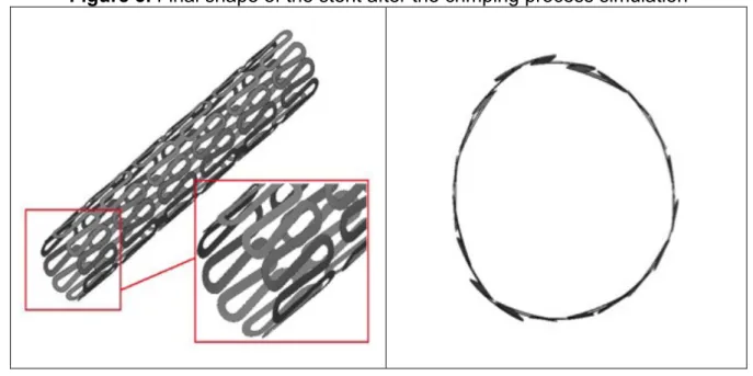
The Figure 3 illustrates the final shape of the stent after the crimping process simulation by finite elements in the software Stampack®. During the crimping process, the percentage reduction of the stent diameter was 52,6%. Hence, the initial diameter of the stent of 1,90 mm has decreased to the 0,95 mm. It is interesting to note that the final shape of the stent and balloon are not circular after the crimping, as can be seen in the
Figures 3 and 4. Indeed, the folds of the balloon cause irregularities in their shape.
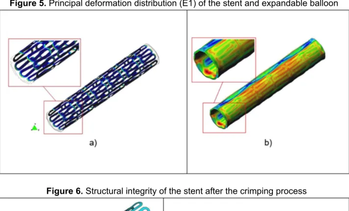
Furthermore, the balloon folds cause an irregular strain distribution in the balloon and stent according to the Figure 5.
The Figure 5 shows the principal strain fields from stent and balloon after the crimping simulation. The maximum value of the principal deformation, E1, in the stent is approximately 0.06 according to the results from the Stampack® software. This strain magnitude does not cause any risk of damage in the stent structure. In the folds regions of the balloon, the principal deformation of the balloon stent is negligible. On the other hand, the principal deformation magnitude in the more thin balloon material thickness is also 0.06. Although this strain magnitude is relatively high, structural integrity of the balloon is preserved since its material is hyperelastic. Moreover, it is expected that the hardening of
the stent material caused by the plastic strain can avoid its slipping on the external surface of the balloon after the crimping.
Figure 3. Final shape of the stent after the crimping process simulation
Figure 4. Final shape of the expandable balloon after the crimping process simulation
The structural integrity analysis of the stent may be done using the results from
Figure 6. From this figure, it is observed the presence of wrinkles in the regions of the
stent structure subjected to the compression plastic strain. The stent structure is also subjected to the thinning due to the tension stress caused by the crimping process. Nevertheless, it can be seen in the fig. 6 that the severity of the wrinkling (color green) and the thinning (color blue) in the stent structure is relatively low. Hence, since the stent is subjected to the weak wrinkling and thinning, the expansion process in the angioplasty will not be affected by the residual plastic strain caused by the crimping process.
Figure 5. Principal deformation distribution (E1) of the stent and expandable balloon
Figure 6. Structural integrity of the stent after the crimping process
CONCLUSIONS
In this work, it was studied the structural integrity of the balloon and stent in the crimping process by using the finite element method. It was considered, in this analysis, a more realistic geometrical model of a tri-folded balloon. It was demonstrated that the strain distribution of the balloon and stent is not symmetrical due to the folds considered in the geometrical model of the balloon. In the previous work, Araújo et al. (2009) shown that the strain distribution of the balloon with unchangeable thickness is symmetrical along its external surface. Furthermore, the maximum value of the principal deformation in the balloon with unchangeable balloon is smaller than the values have obtained in this work. Thus, it is supposed that the geometrical model of the balloon with folds should be used in the analysis of the structural integrity of the stent and the balloon in the crimping process. Although the maximum value of the principal deformation for the folded balloon model could not be negligible, it was not observed the presence of strong wrinkling or thinning in
the stent after the crimping. From the maps of the final shape and strain distribution, it was also verified that the structural integrity from balloon was also preserved. Indeed, the residual plastic strain field caused the hardening of the stent which avoids its slipping on the balloon after the crimping. In the future, it will be estimated the magnitude of slipping force between the balloon and the stent due to plastic strain distribution caused by the crimping process.
ACKNOWLEDGEMENTS
The authors would like to thank the financial support provided by the FAPEMIG (Fundação de Amparo à Pesquisa do Estado de Minas Gerais).
REFERENCES
ARAÚJO, R., Desenvolvimento e Avaliação de Geometrias de Stents
Cardiovasculares Considerando Parâmetros Mecânicos e de Implantação. Tese de
Doutorado, Programa de Pós-Graduação em Engenharia Mecânica, Universidade Federal de Uberlândia, Uberlândia, M.G., Brasil, 2016.
ARAÚJO, R.; OLIVEIRA, S. A. G.; GUIMARÃES, T. A., Numerical Simulation of the Crimping Process in Stents. In: Procedings of the Brazilian Congress of Mechanical
Engineering 2009 (COBEM 2009), 2009.
CHUA, S. N. D.; MAC DONALD, B. J.; HASHIMI, M. S. J. Finite Element Simulation of stent and balloon interaction. Journal of Materials Processing Technology, Vol. 143-144, pp. 591 – 597, 2003.
GRUNTZIG, A. R.; SENNING, A.; SIEGENTHALER, W. E. Nonoperative dilatation of coronary-artery stenosis – percutaneous transluminal coronary angioplasty. N Engl J.
Med.; Vol. 301, pp 61-8, 1979.
JIE, Y.; MINGBANG, L.; NAN, H.; TIANXUE, Y.; QUANXING, D.; SHUWEN, M. Simulation of the Stent Expansion by Finite Elements Method, IEEE 2009, 2009.
LALLY, C.; DOLAN, F.; PRENDERGAST, P. J. Cardiovascular Stent Design and Vessel Stress: a Finite Elements Analysis, Journal of Biomechanics, Vol. 38, pp. 1574 – 1581, 2005
LANGONI, A. M.; ARAÚJO, R.; OLIVEIRA, S. A. G.; GUIMARÃES, T. A. A Finite Elements Analysis of the Perrformance of Stents fof Angioplasty Using the Hydroforming Process,
In: Procedings of the Congress Iberian Latin American of Methods Computacional in Engineering 2006 (CILAMCE 2006), 2006.
LIANG, D. K.; YANG, D. Z.; QI, M.; WANG, W.Q., Finite Elements Analysis of the
Implantation of expandable-balloon stent in a stenosed artery. International Journal of
RONDEAU, F.; PILET, P.; HEYMANN, D.; CROCHET, D.; GRIMANDI, G. Balloon Surface Changes After Stent Deployment: Influence of the Crimping Technique, Éditions
Scientifiques et Medicales, Vol. 23, pp. 357 – 362, 2002.
SERRUYS, P. W.; KUTRYK, M. J. B. Handbook of Coronary Stents, Ed. Martin Dunitz, 1998.
Recebido em: 24/11/2018 [1] Aprovado em: 18/04/2019