Effects of Obstacles on the Dynamics of
Kinesins, Including Velocity and Run Length,
Predicted by a Model of Two Dimensional
Motion
Woochul Nam, Bogdan I. Epureanu*
University of Michigan, Ann Arbor, Michigan 48109-2125, United States of America
Abstract
Kinesins are molecular motors which walk along microtubules by moving their heads to dif-ferent binding sites. The motion of kinesin is realized by a conformational change in the structure of the kinesin molecule and by a diffusion of one of its two heads. In this study, a novel model is developed to account for the 2D diffusion of kinesin heads to several neigh-boring binding sites (near the surface of microtubules). To determine the direction of the next step of a kinesin molecule, this model considers the extension in the neck linkers of kinesin and the dynamic behavior of the coiled-coil structure of the kinesin neck. Also, the mechanical interference between kinesins and obstacles anchored on the microtubules is characterized. The model predicts that both the kinesin velocity and run length (i.e., the walking distance before detaching from the microtubule) are reduced by static obstacles. The run length is decreased more significantly by static obstacles than the velocity. More-over, our model is able to predict the motion of kinesin when other (several) motors also move along the same microtubule. Furthermore, it suggests that the effect of mechanical interaction/interference between motors is much weaker than the effect of static obstacles. Our newly developed model can be used to address unanswered questions regarding degraded transport caused by the presence of excessive tau proteins on microtubules.
Introduction
Cells use various motor proteins for active transport along the cytoskeleton. Among these pro-teins, kinesin-1 is responsible for the anterograde transport along microtubules (MTs). The two identical heads of kinesin-1 are connected to their neck linkers (NLs), which are composed of fourteen amino acids (AAs). NLs are wrapped around each other at the neck forming a coiled-coil structure. The neck is attached to a cargo linker, whose other end is connected to a tail domain where a cargo binds. MTs consist of numerous tubulins where the kinesin heads can successively bind in a stepping process. Kinesins repeat one mechanochemical cycle per a11111
OPEN ACCESS
Citation:Nam W, Epureanu BI (2016) Effects of Obstacles on the Dynamics of Kinesins, Including Velocity and Run Length, Predicted by a Model of Two Dimensional Motion. PLoS ONE 11(1): e0147676. doi:10.1371/journal.pone.0147676
Editor:Keng-Hwee Chiam, ASTAR Bioinformatics
Institute, SINGAPORE
Received:November 9, 2015
Accepted:January 6, 2016
Published:January 25, 2016
Copyright:© 2016 Nam, Epureanu. This is an open access article distributed under the terms of the
Creative Commons Attribution License, which permits unrestricted use, distribution, and reproduction in any medium, provided the original author and source are credited.
Data Availability Statement:All relevant data are within the paper and its Supporting Information files.
Funding:This work was supported by National Science Foundation, DMI-0800202 (http://www.nsf. gov/). The funders had no role in study design, data collection and analysis, decision to publish, or preparation of the manuscript.
Recent experiments suggest that other proteins attached to the MT surface can act as obstacles for kinesins [15–21]. Kinesin motion can be affected also by other nearby kinesins. Leduc et al. [15] observed that the velocity of kinesins decreases dramatically when the number of motors on a MT exceeds a critical value. Furthermore, nonmotile kinesin mutants bound on MTs decrease the velocity and the run length of other walking kinesins [17]. Moreover, the motion of kinesin is inhibited also by MT associated proteins such as tau. The effects of tau proteins on kinesin and dynein have been compared by Dixit et al. [18], where it was revealed that the dependency of kinesins on tau proteins bound to the MT is much stronger than that of dynein. Experiments with cargoes inside cells also suggest that tau proteins decrease the transport dis-tance of molecular motors [20].
Several models have been proposed to describe the motion of kinesin heads [22–27], focus-ing mainly on the one dimensional motion of the kinesin head. However, several experiments with static obstacles suggest that kinesins can bypass obstacles by executing 2D movements along the MT surface [17,19,28]. To capture this 2D stepping motion, we first develop a new model to capture the diffusive motion of kinesin heads in the absence of obstacles. Various equations (i.e., Fokker-Plank equation), models (i.e., a worm-like chain model (WLC) [29]), and experimental results (i.e., unfolding of the coiled-coil structure [30]) are coupled in our model. Next, a deterministic model and stochastic model are developed by using the diffusion model to predict the motion of kinesin in the presence of obstacles.
Model
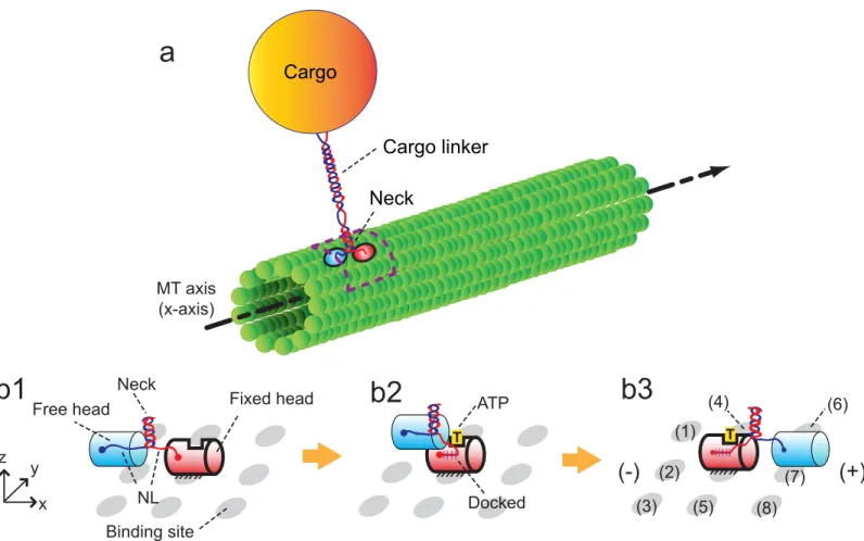
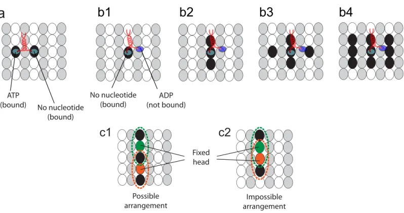
The walk cycle of kinesins is realized by their structural changes and by diffusion of its heads. It begins from a state where ATP is not bound on the fixed head of the kinesin, as described in
Fig 1b1. The structural change fromFig 1b1 to 1b2is caused by the binding of ATP to the fixed head. This binding creates the bonds between the fixed head and its NL. After the structural change, the free head diffuses until it reaches one of the eight neighboring binding sites (1)–(8), as shown inFig 1b3. The diffusive motion of the free head is important because it determines the direction of the kinesin walk.
The motion caused by the structural changes is considered in our study by using the results of a previous study [31]. Specifically, the head which is not bound to the MT moves about 6 nm along the MT axis in a very short time immediately following a structural change. The subsequent motion (i.e., diffusion of the free head) is captured by using the developed methods explained below.
Forces acting on kinesin structure
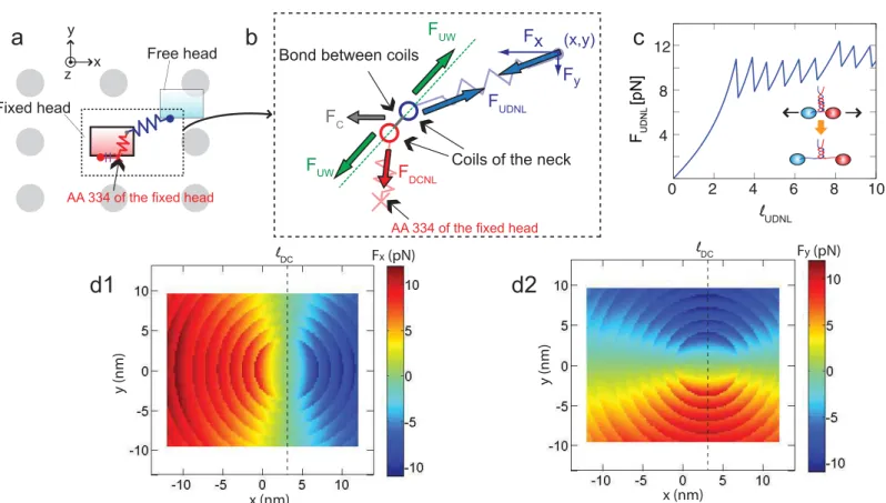
The forces acting on the free head (i.e.,FxandFyinFig 2b) are calculated by considering three different forces: forces,FDCNL, acting on the docked NL, forces,FUDNL, acting on the
undocked NL, and forces,Fc, transferred from the cargo to the neck via the cargo linker. For a
given position of the free head, the neck is located at the position where the vector summation of these forces is zero.FDCNLandFUDNLare calculated by using the WLC [29,32] as
FNL¼ kBT
‘p
1
4 1
‘NL ‘c
2
þ‘NL ‘c
1
4
!
; ð1Þ
wherekBis Boltzmann constant,T(= 300 K) is the absolute temperature, andℓp(= 0.6 nm) is the persistence length.ℓcis the contour length of the NLs which can be calculated asNAAℓa,
whereℓa(= 0.4 nm) is the contour length between two adjacent AAs.NAAdenotes the number
of AAs in the NLs.NAAis equal toNAA, 0+ 3.5nuw, whereNAA, 0is the number of AAs in the
NLs when every bond in the neck is intact.nuwis the number of unwound turns of the neck.
Because the unfolding of one turn increases the number of AAs by 3 or 4 for each NL, the
coef-ficient 3.5 is used when calculatingNAAwithnuw.NAA, 0is 14 (AA 325–338) for the undocked
NL and 4 (AA 335–338) for the docked NL because AA 334 of the docked NL is tightly bound to thefixed head with two backbone hydrogen bonds [33]. The neck consists of two coils Fig 1. Walking motion of a kinesin molecule on the MT.(a) depicts one kinesin molecule transporting a cargo by walking on the MT. The dotted box indicates the domain where the motion of the kinesin head is realized. (b) shows the components of the kinesin structure and the procedure for its walking motion. The kinesin has one pair of identical heads and NLs.xrepresents the direction of MT-axis, andyis the tangential direction of the MT. xy-plane represents the outer surface of the MT. The cylinder with bold outlines denotes the fixed head on the MT, and the cylinder with thin outlines is the free head. The neighboring binding sites of the kinesin are shown as gray ellipses. The plus and minus signs denote the polarity of the MT.
which are connected to each NL, as shown inFig 1. The coils are coiled with each other for about 10 turns, and that coiled-coil structure is maintained by hydrophobic interactions [34]. In experiments performed by Bornschlogl et al. [30], it is observed that each turn of the neck can be unwound when stretching forces of about 10 pN are applied. This behavior changes the relation between the force acted in the NL and its length when the force reaches the unwinding force values, as shown inFig 2c. The force is also affected byℓDCwhich is the distance between
AA 324 and AA 334 of the NL in a condition when they are docked to thefixed head. This length determines the position of AA 334 of the docked NL, as shown inFig 2a. Thus, the mag-nitude of the force in the x and y directions (i.e.,FxandFy) acting on the free head is symmetric aboutx=ℓDC, as shown inFig 2d. The refolding of the neck is also considered by assuming
that the force-displacement relation for stretching is the same when releasing that stretching. When calculatingFxandFy, the state is first considered where every chemical bond between two coils of the neck is connected (i.e.,nuw= 0). The moment caused byFcon the neck is
negli-gible becauseFcacts at the center of the neck. The two coils align along a line which is indicated
with the dotted line inFig 2b, so that the net moment caused byFUDNLandFDCNLis zero.
However, both coils are stretched by the forceFUWalong the dotted line inFig 2b. The
magni-tude ofFUWcan be calculated usingFc,FDNL, andFUDNL. The bonds of the neck can be broken
or intact depending onFUW. IfFUWis less than the force required to unwind the first bond of
the coiled-coil structure, thenFxandFyare determined byFUDNL. If the calculatedFUWis
Fig 2. Spring model of kinesin NLs.(a) shows a kinesin molecule and the binding sites around it. Note that the directions ofx,y, andzaxis are the same with those inFig 1, and the view direction is along thezaxis. NLs are depicted with springs, and gray circles represent the neighboring binding sites. (b) is a schematic cross section through the coiled-coil structure of the neck. The coils are bonded to each other by using the interactions of their AA residues. The neck is connected to two springs corresponding to the docked NL and undocked NL. (c) shows the changes of the force (FUDNL) over the length (ℓUDNL) of
undocked NL. (d1) depicts the calculatedFx(x,y), where (x,y) denotes thexandypositions of the free head. (d2) shows the calculatedFy(x,y).
larger than the force to unwind the first bond, the simulation step is performed again, unwind-ing the first turn of the neck (i.e.,nuw= 1). This procedure is repeated untilFUWbecomes less
than the force required to unwind the subsequent turn.
Diffusive motion of kinesin head
To determine the direction of the kinesin step, the diffusive motion of the free head has to be considered. However, calculating that diffusive motion at every walk cycle requires intensive computations. To reduce computation effort dramatically, the following method is used. First, the probability of the direction of step is calculated by solving the Fokker-Plank equation on the position of the free head. Then, a random number is generated at every step of kinesins. Next, the direction of each step is determined by comparing the random number to the calcu-lated probability. Because a solution of the Fokker-Plank equation can be used at every step of kinesins, this method enables us to determine the stochastic two dimensional walking motion of kinesin with higher computational efficiency.
The probability density for the position of the free head is calculated over time by solving the following Fokker-Plank equation (in a domain depicted inFig 1awith a dotted box)
@p @t ¼D
@2
p @x2 þD
@2
p @y2
@ @x
Fx
gp
@ @y
Fy
gp
; ð2Þ
wherexandyare coordinates of the free head with respect to thefixed head along the MT-axis and along the tangential direction of the MT, respectively. The software COMSOL is used to solve this partial differential equation with thefinite element method.pis the probability density function of the position of the free head.Dis the diffusion coefficient, andγis the drag coefficient of the free head in water. The head is assumed cylindrical with a length of 7 nm and a diameter of 4.5 nm. These dimensions of the head are obtained from a previous study on the crystal struc-ture of kinesin heads [35].γis calculated to be 5.625 × 10⁻⁸g/s by using the method of Swanson et al. [36] for the drag coefficient for a cylinder moving at low Reynolds numbers. Then, the dif-fusion coefficient can be calculated as 73.6μm2/s for a temperature of 300 K. Note that the dependency ofγandDon the direction of motion is negligible for such cylinder dimensions [36]. The effect of the motion along the radial direction of the MT is assumed to be negligible.
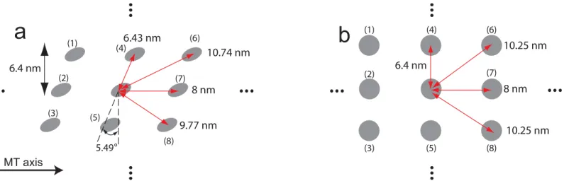
The probability of stepping to the left sites (i.e., site (4) or (6) inFig 3) can be different to the probability of walking to the right sites (i.e., site (5) or (8) inFig 3) because there is a mismatch
Fig 3. Lattice array of MTs and the distance between adjacent binding sites.(a) shows the binding sites for MTs of a helical structure. (b) depicts the binding sites in the absence of a mismatch in the lattice array.
in the lattice of MTs due to a variable number of protofilaments. However, Yildiz et al. [37] observed that the probability of kinesin to move left is the same as the probability to move right. This observation suggests that the effects of the mismatch in the lattice of MTs are not significant. To confirm that this effect is small, the distance from the binding sites to the center of the fixed head is calculated. For a MT diameter of 26.5 nm and a number of 13 protofila-ments, the angle of the mismatch is approximately 5.49°(= atan(8/(26.5 ×π))). For a helical MT structure, the distances to the two diagonal sites (left and right) are 10.74 nm and 9.77 nm, respectively, as shown inFig 3a. In the absence of a mismatch in the lattice array, these dis-tances are both 10.25 nm. Because the change in the distance due to a lattice mismatch is not considerable (i.e., only about 5%), isotropic diffusivity can be used in this study.
Two types of boundaries are considered, as shown inFig 4a. Absorbing boundary condi-tions (i.e.,p= 0) are applied at the binding sites. Reflective boundary conditions (i.e., no flux along the normal direction to the boundary) are used for the other boundaries.
Fig 4bshows one example of the spatial probability density for the free head. The probability that the free head binds to a certain binding site is obtained by integrating over time the fluxP_ of the probabilityflowing out through the boundaries of the site (which is shown inFig 4c).
Binding with tilted posture
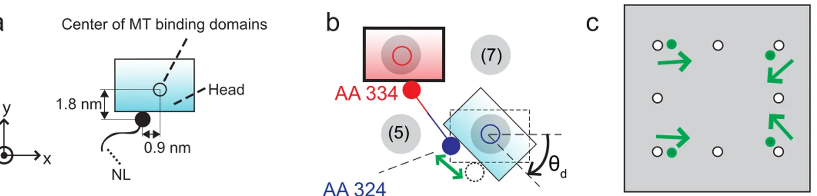
To consider the effects of the affinity of the kinesin head to the binding sites, the positions of the specific AAs of the free head can be examined. First, AA 142–145, AA 273–281, AA 238 and AA 255 are responsible for binding on the MT [33]. Thus, it is assumed that the head binds to a binding site when the geometric center of these AAs reaches the binding site. Second, AA 324, which connects the NL to the head, is located about 0.9 nm away from that geometric center along the x direction and about 1.8 nm away along the y direction, as shown inFig 5a. Due to this structure, when the free head is located at a diagonal site with a tilted posture, the length of the NLs to reach that site is shorter than the length when the free head reach the site with no rotation, as shown inFig 5b. Thus, it is assumed that the binding to the diagonal site with tilted posture is favorable to the kinesin free head. The parameterθdrepresents the allow-able tilting angle. We further hypothesize that if the free head is tilted with an angle larger than
θd, then the affinity between the binding site and the AAs of the free head which interacts with the binding sites is not strong enough to cause binding. When the geometric center of AAs responsible for binding is located at the diagonal binding site, and the tilted angle is less than
θd, the interaction between the head and the site is strong. Then, the head binds to the site. Sub-sequently, the head is aligned along the MT by that interaction. To mathematically model this behavior, the positions of the absorbing boundaries in the domain are calculated as follows. Fig 4. Diffusive motion of kinesin head in the absence of obstacles.The gray area of (a) describes the domain whereEq 2is solved. (b) is the spatial probability density of the position of the free head after 1μs after the diffusion has started. (c) shows the rate of the probability density flow out through each absorbing boundary.
First, we locate the geometric center of the AAs responsible for binding of the free head at a certain binding site (e.g., site (8)), as shown inFig 5b. Then, we rotate the free head with respect to the geometric center by an angleθd. Then, the position of the binding is determined as the relative position of AA 324 of the free head with respect to the position of AA 334 of the fixed head. For example, whenθdis 47°, the distances between the diagonal site and the fixed head decreases by 14.7% compared to the same distance whenθdis 0°.Fig 5cshows the position of binding sites obtained using this method. Note that this behavior is only applicable to the diag-onal sites because there is not enough space for the free head to tilt when the head is near the side, forward, or backward binding sites due to the geometric interference between the free head and the fixed head.
Comparison to experimental data
The diffusion model has three parameters;ℓDC,θd, anddside, wheredsideis the distance between
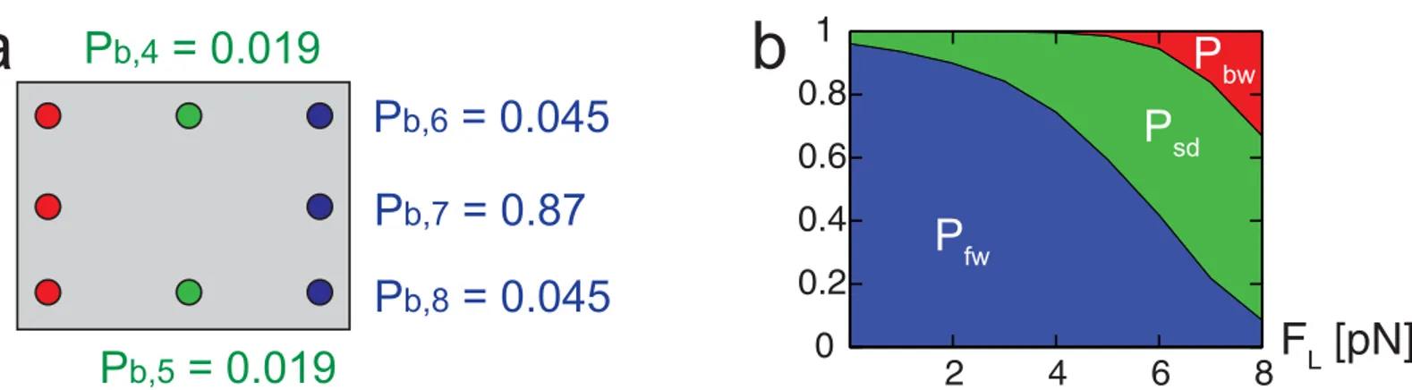
two adjacent binding sites along the tangential direction of the MT. The values of these three parameters are determined by calculating the probability (Pb,i) of the free head to bind at each neighboring binding site and by comparing it with experimental data. Yildiz et al. [37] tracked the motion of kinesin heads by labeling them with quantum dots. Their results show that 13% of the kinesin steps involve motion along the tangential direction of the MT, and 70% of that lateral motion occurs together with the motion toward the plus end of the MT. Also, the mea-surements of Nishiyama et al. [38] show that the probability of backward steps increases expo-nentially over the resisting load acting on the cargo. According to their observations, the probability ratio of forward and backward steps is about 1.3 when the resisting load is about 7 pN. A set of parameters (ℓDC= 2.9 nm,dside= 6.4 nm, andθd= 47°) satisfies the probability
of step observed in both experiments. The probabilities of forward, backward and sideway step in the absence of resisting loads are presented inFig 6a.ℓDCanddsideare similar to the
mea-sured values of the previous studies. The value ofℓDCin the crystal structure of kinesin [39] is
about 3 nm. Also,dsideof 6.4 nm can be obtained when the diameter of the MT is 26.5 nm.
This diameter value is in the range of the actual diameters of MTs observed in the cell [40,41].
Effects of load on the probability of step
The external load acting on the cargo affects the probabilities of kinesin step. When an external load is applied to the cargo, it is transferred to the cargo linker. That force,Fc, changes the force acting on the free head (i.e.,FxandFy). As a result, the probabilities of sideway and backward Fig 5. Free head when binding to diagonal binding sites.(a) depicts the positions of AA 324 with a filled circle. The geometric center of the binding domains which interact with binding sites is shown as a hollow circle. (b) depicts the assumption that the free head is likely to bind to the diagonal site with a tilted posture. (c) shows with filled circles the position of the absorbing boundaries of the diagonal sites which correspond to binding with a tilted posture.
steps increase over the loads, as shown inFig 6b. Note that the direction of the load is toward the minus end of the MT.
Effects of unwinding the neck and binding with a tilted posture
Both the unwinding of the neck and the binding with tilted posture are necessary to obtain the probability of the direction of a step measured in experiments [37]. To check the effects of unwinding the neck on the diffusion,Pb,iis obtained using the model which allows the binding with tilted posture but does not allow neck unwinding. Uoff+ ToninTable 1represents this
case. The equation used to calculateFNLis the same asEq 1except that the value ofNAAis fixed asNAA, 0. Similarly, Uon+ Toffrepresents the case of constraints which do not allow
unwinding of the neck but allow binding with tilted posture. Uon+ Tonrepresents the case
where both unwinding of the neck and binding with a tilted posture are allowed. The binding probability presented inTable 1suggests that both behaviors are necessary to obtain values similar to thosePb,imeasured experimentally [37].
Number of binding sites occupied by kinesin
The number of binding sites occupied by kinesin molecules depends on the chemical state of its head. The kinesin head has a strong affinity to the MT when it has ATP or no nucleotide [42]. The head has a low affinity to the MT if it has adenosine diphosphate (ADP). When one head has ATP and the other head has no nucleotide, as described inFig 1b3, both heads are strongly bound to the MT. Thus, two sites are occupied by the kinesin in this state, as shown in
Fig 7a.
When one head has no nucleotides or ATP and the other has ADP, as shown inFig 1b1 or 1b2, one head diffuses around the (other) head which is strongly bound to the MT [43,44]. For these states, the strongly bound head (i.e., the head with no nucleotide or with ATP) occupies a Fig 6. Probability of binding at neighboring sites.The numbers in (a) denote the probability to bind (Pb,i) at each site in the absence of external loads.
The probabilityPbof backward steps is not indicated because its value is very small. (b) shows the changes in the probabilities of forward (Pfw=Pb, 6+Pb, 7 +Pb, 8), sideway (Psd=Pb, 4+Pb, 5), and backward (Pbw=Pb, 1+Pb, 2+Pb, 3) steps over the external load.
doi:10.1371/journal.pone.0147676.g006
Table 1. Binding probability (Pb,i) to each site for the model with various constraints.
Site Experiment Uon+ Ton Uoff+ Ton Uon+ Toff
(4) or (5) 0.0195 0.0193 7 × 10⁻⁵ 0.021
(6) or (8) 0.0455 0.0452 1.2 × 10⁻⁶ 0.00169
(7) 0.869 0.871 0.99 0.954
single site. Because the free head is diffusing around the fixed head, it is possible that the heads of other kinesin molecules cannot bind to the sites around this kinesin molecule. Several possi-ble scenarios of binding sites, which are not accessipossi-ble for other kinesin molecules, are studied, as shown inFig 7b. Among them, the second case, depicted inFig 7b2, is selected based on experiments performed by Telley et al. [17]. They observed the kinesin motion on MTs on which other immobile kinesins are attached. The state of the immobile kinesins is same with that of the walking kinesin when one of its head is bound to the MT and the other head is free. Also, the motion of walking kinesins depends on the number of binding sites occupied by the immobile kinesins. Thus, the velocity of walking kinesins in the presence of immobile kinesins can be used to determine the number of binding sites occupied by the kinesin in this state. Details are provided in the results.
Since the unbound heads do not remain at one site, they can share the same site at different times, as shown inFig 7c1. However, a head cannot bind to a site if the site is affected by the unbound head of other kinesins, as shown inFig 7c2.
Results
The motion of kinesin is affected by the interaction between obstacles and kinesins and by the number of the obstacles on the MT. Our model is used to characterize the interaction by locat-ing obstacles near a kinesin molecule. By uslocat-ing experiments, where the velocity and run length of kinesins are observed in the presence of immobile kinesins, the value of parameters regard-ing the interaction between kinesin molecules are obtained. Then, the velocity and run length Fig 7. Binding sites occupied by kinesin heads.The black ellipses represent the binding sites occupied by the kinesin. The gray and white ellipses areα
andβtubulins of the MT. Note that the kinesin head can only bind toβtubulins. (a1) Two sites are occupied by the kinesin when its two heads are strongly bound. (b) depicts possible scenarios when one of the kinesin heads can be unbound and the other head is strongly bound. The kinesin can occupy one (b1), three (b2), five (b3), or nine (b4) binding sites. (c1)-(c2) shows two examples of cases where sites occupied by two kinesin molecules are adjacent, allowing for interference. Both kinesins have one unbound head and one bound head. The dotted circles represent the sites occupied by kinesin heads.
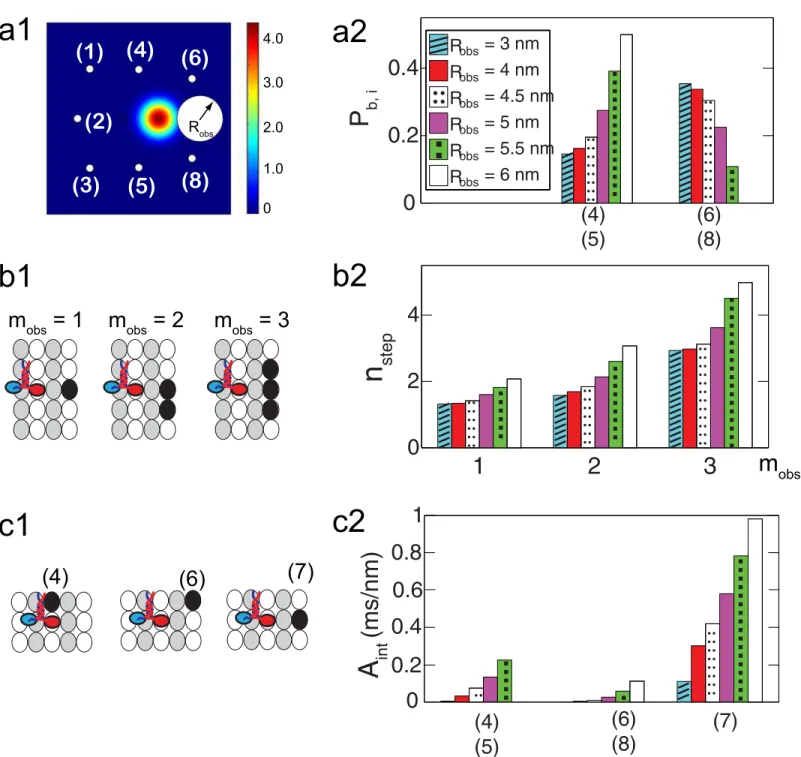
To characterize the interaction between kinesins and their neighboring obstacles, the size of the region which the kinesin head cannot reach due to the obstacle (Robs), the number of
bind-ing sites occupied by a sbind-ingle obstacle (mobs), and the degree of interference (Aint) between the
kinesin and the obstacle are considered. When a binding site is occupied by obstacles, the free head is not able to reach it. Thus, a reflective boundary is located at that binding site. The shape of the reflective boundary is assumed to be circular, as shown inFig 8a1. Next, the degree of interference (Aint) between obstacles and the free head is calculated by using the probability
density of the free head to reach the boundary as
Aint¼ Z tf
t0
I
Cobs
p d‘ dt; ð3Þ
wheret0andtfare the initial andfinal time, respectively, when solvingEq 2.Cobsis the refl
ec-tive boundary of obstacles located near the kinesin. Then, the unbinding probability of kinesin per step can be calculated by usingAintas
Pub¼P
0
ubþDPub;obs; where DPub;obs¼aobsAint;
ð4Þ
whereP0
ubis the unbinding probability per step when every neighboring binding site is not occupied by obstacles.P0
ubare obtained from our previous model [45].ΔPub, obsis the change in
the unbinding probability due to obstacles. Note that the kinesin dissociates from the MT mostly when one of its heads is diffusing [10,45]. Thus, it is assumed that the increase of the unbinding probability due to obstacles during that diffusion is also very large compared to
ΔPub, obsfor other kinesin states.αobsis the parameter of the model which calculates the
proba-bility to unbind when the free head interacts with the obstacles.
If the site ahead of the fixed head is occupied by a the small obstacle, the kinesin is likely to bypass it by moving forward to a diagonal site. However, for a large obstacle, the probability to move to one of the the side sites is larger than that of moving to a forward diagonal site, as shown inFig 8a2. Thus, the kinesin needs a larger number of steps (nstep) to bypass an obstacle
whenRobsis large, as shown inFig 8b2.nstepalso increases withmobsexponentially. Note that
Aintis maximum when the forward site is occupied by an obstacle, as shown inFig 8c2. This
means that the interference of obstacles is most significant when they are located in front of kinesins.
Static obstacles
The parameters describing the effects of obstacles (i.e.,Robs,mobs, andαobs) depend on the type
absence of obstacles. The values ofRobsandmobsare obtained by using the changes in the
kine-sin velocity. The observed decrease of the run length is used to calculate the value ofαobs.
Velocity in the presence of static obstacles. The motion of the heads of the immobile
kinesins is the same with that of the walking kinesin when one of its head is bound to the MT Fig 8. Motion of kinesin in front of a single obstacle.(a1) shows the probability density over the domain after 1μsif a single obstacle ofmobs= 1 is ahead of the kinesin. The blocked region formed by the obstacle is included into the domain with the reflective boundary. (a2) denotes the probability to bind to each site. The numbers in parentheses represent the position of the sites shown in (a1). (b1) demonstrates different types of obstacles which occupy one, two or three binding sites. The black ellipses represent the binding sites occupied by a single obstacle. (b2) shows the number of kinesin steps (nstep) to proceed 8 nm along the MT axis for variousmobs. (c1) illustrates cases where one of the neighboring sites becomes unaccessible due to an obstacle. (c2) denotes the degree of interference for the cases shown in (c1).
velocity predicted by the model to the velocity observed in the experiments, the molar ratioρ
of 0.08 is used formobs= 1, 0.0346 (= 8% × 0.4352) is used formobs= 3,ρof 0.0286 (= 8% ×
0.3572) is used formobs= 5, andρof 0.0147 (= 8% × 0.1843) is used formobs= 9.
To obtain the value of aforementioned parameters, we developed a mathematical equation capable of calculating the (average) velocity and run length for various numbers of obstacles by using the behavior of kinesin in front of single obstacles, as explained previously. Specifically, velocities can be calculated as
VðrÞ ’V0 1
1þX
k akr
k; ð5Þ
whereV(ρ) is the velocity for a molar ratioρ.V0is the velocity in the absence of obstacles. The
derivation of this equation is provided inS1 File. The coefficientakis determined bynstep,
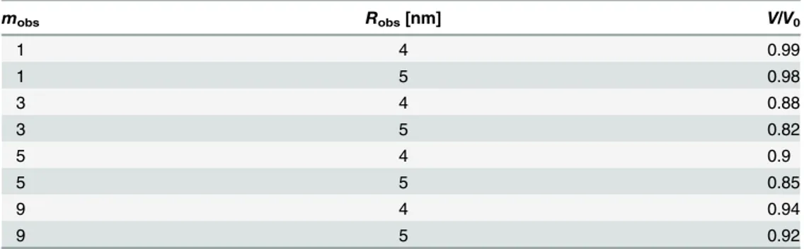
which is calculated using the diffusion model.Table 2shows the velocities obtained forRobs= 4
and 5 nm andmobs= 1, 3, 5, and 9. The values of these parameters were determined asRobs= 5
nm andmobs= 3 for the immobile kinesin obstacles. Note thatmobs= 3 is also used for the
walking kinesin when one of its head isfixed and the other is not bound.
Run length in the presence of static obstacles. The run length of the deterministic model
can be calculated as
RLðrÞ ¼RL0 1
1þX
k bkr
k VðrÞ
V0 ; ð6Þ
whereRL(ρ) andRL0are the run length in the presence and absence of obstacles, respectively.
The values ofbkdepend onαobs. The derivation of this equation is provided inS1 File.
To obtain precise values of the parameters, the time and spatial resolutions used in experi-ments were applied to our stochastic model. The mathematical models in Eqs5and6are based on the assumption that the time and spatial resolution is sufficiently small. However, a finite resolution is used in the experiments. Thus, the velocity and run length are obtained again by
Table 2. Kinesin velocity for variousmobsandRobs.
mobs Robs[nm] V/V0
1 4 0.99
1 5 0.98
3 4 0.88
3 5 0.82
5 4 0.9
5 5 0.85
9 4 0.94
9 5 0.92
using a stochastic mathematical model with the resolution of the experiments. The stochastic model was developed by integrating the diffusion model with a previously developed model which describes the stochastic motion of the kinesin in the absence of obstacles [45]. Details on the stochastic model are described inS1 File. The stochastic model withRobs= 5 nm and
mobs= 3 provides velocities similar to those obtained usingEq 5. The value ofαobswhich leads
to a good match with experimentally observed run lengths is of 0.044 nm/ms.
It is worthy to note the effect of obstacles on the run length and velocity of kinesin. The run length decreases as the unbinding probability is increased due to obstacles. The effect of unbind-ing probability on the velocity depends on the concentration of obstacles anchored on the MT. When the concentration of obstacles on the MT is small, the velocity does not change. However, if the number of molecules is considerable, both the size of obstacles and the degree of interfer-ence (Aint) should be considered. If the size of obstacles (which is considered by usingRobs) is
small, the probability regarding the direction of step does not change significantly. Thus, the change in velocity is very small. However, ifRobsis large andAintis small, the kinesins have
more chances to walk sideways. In this case, the velocity can be reduced over the concentration of obstacles. If bothRobsandAintare large, both the probability to walk sideway and the
unbind-ing probability increase. As a result, the kinesin is likely to unbind from the MT near obstacles before walking to side binding sites. Thus, the decrease in the velocity is not considerable.
Moving obstacles
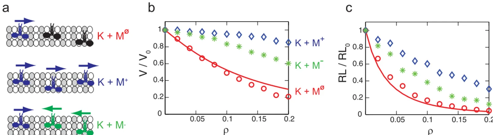
Since the state of immobile kinesins is the same with the state of walking kinesins when they wait for ATP to bind, the interactions between moving kinesins and immobile kinesins, which is characterized in this study, can be used to consider the interaction between moving motor proteins. The minus-end directed motors, such as dyneins, are considered in our model simply by reversing the direction of the steps of kinesin. (K + MF) represents the situation when the motion of kinesin is disturbed by immobile kinesins. Also, kinesins can walk while surrounded by other kinesins (K + M+) or in the presence of minus-end directed motors (K + M−). These cases are depicted inFig 9a. The changes of the kinesin motion by surrounding motors are related to the probability of the kinesin to interact with other motors. That probability is high for (K + MF), and is small for (K + M+) due to the motility of the surrounding motors. Thus,
Fig 9. The velocity and run length of kinesins over the density of motors.(a) depicts the motions of the kinesin in (K + MΦ
), (K + M+), and (K + M−)
situations. Motors with an arrow directed to the right are moving kinesins. Motors with an arrow directed to the left are minus-end directed motors. Immobile kinesins are presented as motors without an arrow.ρrepresents the molar ratio of immobile kinesins and tubulins for (K + MΦ
), the molar ratio of walking kinesins and tubulins for (K + M+), or the molar ratio of minus-end directed motors and tubulins for (K + M−). Note that the MT is saturated with kinesins when ρis about 0.43. The line denotes the velocity and run length for (K + MΦ
) obtained from Eqs5and6. The results shown as circles, stars and diamonds are calculated from our stochastic model.
of AAs in the NLs. Our model provides consistent results with their findings when the number of AAs in the NL is changed from 14 to 17, i.e., changed to the number of AAs in the NLs of kinesin-2. Our model predicts that when NLs of kinesin-2 are used, the probabilities of sideway and diagonal stepping increase by 1% compared to the same probabilities for kinesin-1.
Additionally, according to our model, when a single obstacle ofRobs= 5 nm is located in
front of a kinesin (i.e., site (7)), the value ofAintis 0.46 ms/nm for kinesin-2, which is smaller than the respective one (i.e., 0.58 ms/nm) for kinesin-1. Hence, the interference between the free head of kinesin-2 and obstacles is not as strong as the interference between kinesin-1 and obstacles. This means that kinesin-2 is less likely to unbind from the MT in the presence of obstacles than kinesin-1. Therefore, the model predictions are consistent with the measure-ments of Hoeprich et al. [46] who observed that the run length of kinesin-1 decreased due to the presence of tau proteins, whereas and the run length of kinesin-2 did not decrease significantly.
Probability of large step
Another use of our model includes studying calculating the probability of larger steps (i.e., probability of stepping to distant binding sites). The domain, which is shown inFig 4a, is extended to considerPb,iof twenty four neighboring binding sites. Also, the forces acting on the head (i.e.,Fx(x,y) andFy(x,y)) are calculated in this extended domain. Next, the diffusion of the free head is obtained, as shown inFig 10. The result suggests that binding to sites far from the fixed head is possible but the probability of such events is very small. The sum of the probabilities (=Pb, 9+Pb, 10+Pb, 11+. . .+Pb, 24) is about 1.3 × 10⁻⁸.
Discussion
A diffusion model was developed in this study to predict two dimensional motion of kinesin which is necessary to bypass obstacles. Next, the interference between the walking kinesin and immobile kinesins was characterized by comparing the kinesin motion obtained from the dif-fusion model with experimentally measured velocities and run lengths. By using that interac-tion, the effects of other motor proteins on kinesins are predicted when they move on the same MT. If several kinesins share one MT, their velocities are almost not affected by other kinesins on the MT. The deceleration of kinesins by minus-end directed motors is also not considerable. These results suggest that cells can handle several intracellular transport processes effectively with a small number of MTs. However, both the velocity and run length decrease considerably in the presence of immobile kinesins. As a result, the malfunction of a few motors could degrade the whole transport system.
by tau proteins. However, the transport velocity of cargoes can be modulated by tau proteins. Large cargoes such as mitochondria are transported by several kinesins to overcome large vis-cous forces in the cytoplasm. It is observed that the unbinding rate of kinesins increases and the rebinding rate of kinesins to the MTs decreases in the presence of tau proteins [18,47–49]. Thus, the number of kinesins which effectively transport a large cargo is decreased by tau pro-teins, leading to slower transport of large cargo. Also, this decelerated cargo transport and the attached kinesins can behave as obstacles for other kinesin molecules. As a result, the entire transport system cannot operate properly.
At this point, it is worth to note that the effects of obstacles on the motion of kinesin is important because several neurodegenerative diseases such as Alzheimer’s, Parkinson’s, and Huntington’s disease have been reported to be related to an abnormal intracellular transport [50–52]. The negative effects of obstacles on the intracellular transport have been observed also in vivo. Specifically, the transport of various types of cargoes was decelerated or failed due to an excessive number of tau proteins [53–55]. Thus, the characterization of the motion of kinesin in the presence of tau proteins is necessary to reveal quantitative aspects of the relation between Fig 10. Spatial probability density of the position of the free head in the large domain.
Table A presents the parameters to calculate velocity using the deterministic model. The values of parameters of the mechanistic model are presented in Table B.
(ZIP)
Author Contributions
Conceived and designed the experiments: WN BE. Performed the experiments: WN. Analyzed the data: WN BE. Wrote the paper: WN BE.
References
1. Romberg L, Vale RD. Chemomechanical cycle of kinesin differs from that of myosin. Nature. 1993; 361(6408):168–170. doi:10.1038/361168a0PMID:8421522
2. Mandelkow E, Johnson KA. The structural and mechanochemical cycle of kinesin. Trends Biochem Sci. 1998; 23(11):429–433. doi:10.1016/S0968-0004(98)01278-XPMID:9852761
3. Cross R, Crevel I, Carter N, Alonso M, Hirose K, Amos L. The conformational cycle of kinesin. Philos T Roy Soc B. 2000; 355(1396):459–464. doi:10.1098/rstb.2000.0587
4. Block SM, Asbury CL, Shaevitz JW, Lang MJ. Probing the kinesin reaction cycle with a 2D optical force clamp. Proc Natl Acad Sci. 2003; 100(5):2351–2356. doi:10.1073/pnas.0436709100PMID:12591957
5. Hancock WO, Howard J. Kinesin’s processivity results from mechanical and chemical coordination between the ATP hydrolysis cycles of the two motor domains. Proc Natl Acad Sci. 1999; 96(23): 13147–13152. doi:10.1073/pnas.96.23.13147PMID:10557288
6. Hackney DD. Evidence for alternating head catalysis by kinesin during microtubule-stimulated ATP hydrolysis. Proc Natl Acad Sci. 1994; 91(15):6865–6869. doi:10.1073/pnas.91.15.6865PMID:
8041710
7. Svoboda K, Mitra PP, Block SM. Fluctuation analysis of motor protein movement and single enzyme kinetics. Proc Natl Acad Sci. 1994; 91(25):11782–11786. doi:10.1073/pnas.91.25.11782PMID:
7991536
8. Schnitzer MJ, Block SM. Kinesin hydrolyses one ATP per 8-nm step. Nature. 1997; 388(6640):386–390. doi:10.1038/41111PMID:9237757
9. Visscher K, Schnitzer MJ, Block SM. Single kinesin molecules studied with a molecular force clamp. Nature. 1999; 400(6740):184–189. doi:10.1038/22146PMID:10408448
10. Schnitzer MJ, Visscher K, Block SM. Force production by single kinesin motors. Nat Cell Biol. 2000; 2(10):718–723. doi:10.1038/35036345PMID:11025662
11. Beeg J, Klumpp S, Dimova R, Gracia RS, Unger E, Lipowsky R. Transport of beads by several kinesin motors. Biophys J. 2008; 94(2):532–541. doi:10.1529/biophysj.106.097881PMID:17872957
12. Block SM, Goldstein LSB, Schnapp BJ. Bead movement by single kinesin molecules studied with opti-cal tweezers. Lett Nat. 1990; 348(22):348–352. doi:10.1038/348348a0
13. Vale RD, Funatsu T, Pierce DW, Romberg L, Harada Y, Yanagida T. Direct observation of single kine-sin molecules moving along microtubules. Nature. 1996; 380(6573):451. doi:10.1038/380451a0PMID:
8602245
14. Klumpp S, Lipowsky R. Cooperative cargo transport by several molecular motors. Proc Natl Acad Sci. 2005; 102(48):17284–17289. doi:10.1073/pnas.0507363102PMID:16287974
16. Korten T, Diez S. Setting up roadblocks for kinesin-1: mechanism for the selective speed control of cargo carrying microtubules. Lab Chip. 2008; 8(9):1441–1447. doi:10.1039/b803585gPMID:
18818797
18. Telley IA, Bieling P, Surrey T. Obstacles on the microtubule reduce the processivity of Kinesin-1 in a minimal in vitro system and in cell extract. Biophys J. 2009; 96(8):3341–3353. doi:10.1016/j.bpj.2009. 01.015PMID:19383477
17. Dixit R, Ross JL, Goldman YE, Holzbaur EL. Differential regulation of dynein and kinesin motor proteins by tau. Science. 2008; 319(5866):1086–1089. doi:10.1126/science.1152993PMID:18202255
19. Dreblow K, Kalchishkova N, Böhm KJ. Kinesin bypassing blockages on microtubule rails. Biophys Rev Lett. 2009; 4(01n02):139–151. doi:10.1142/S1793048009000958
20. Trinczek B, Ebneth A, Mandelkow E, Mandelkow E. Tau regulates the attachment/detachment but not the speed of motors in microtubule-dependent transport of single vesicles and organelles. J Cell Sci. 1999; 112(14):2355–2367. PMID:10381391
21. Seitz A, Surrey T. Processive movement of single kinesins on crowded microtubules visualized using quantum dots. EMBO J. 2006; 25(2):267–277. doi:10.1038/sj.emboj.7600937PMID:16407972
22. Taniguchi Y, Nishiyama M, Ishii Y, Yanagida T. Entropy rectifies the Brownian steps of kinesin. Nat Chem Biol. 2005; 1(6):342–347. doi:10.1038/nchembio741PMID:16408074
23. Hendricks AG, Epureanu BI, Meyhöfer E. Mechanistic mathematical model of kinesin under time and space fluctuating loads. Nonlin Dynam. 2008; 53(4):303–320. doi:10.1007/s11071-007-9315-1
24. Kolomeisky AB, Stukalin EB, Popov AA. Understanding mechanochemical coupling in kinesins using first-passage-time processes. Phys Rev E. 2005; 71(3):031902. doi:10.1103/PhysRevE.71.031902
25. Astumian RD, Bier M. Fluctuation driven ratchets: molecular motors. Phys Rev Lett. 1994; 72(11):1766. doi:10.1103/PhysRevLett.72.1766PMID:10055695
26. Bier M, Cao FJ. How occasional backstepping can speed up a processive motor protein. Biosys. 2011; 103(3):355–359. doi:10.1016/j.biosystems.2010.11.005
27. Nam W, Epureanu BI. The effects of viscoelastic fluid on kinesin transport. J Phys: Conden Matt. 2012; 24(37):375103.
28. Dreblow K, Kalchishkova N, Böhm KJ. Kinesin passing permanent blockages along its protofilament track. Biochem Biophys Res Commun. 2010; 395(4):490–495. doi:10.1016/j.bbrc.2010.04.035PMID:
20399751
29. Marko JF, Siggia ED. Stretching dna. Macromol. 1995; 28(26):8759–8770. doi:10.1021/ma00130a008
30. Bornschlögl T, Woehlke G, Rief M. Single molecule mechanics of the kinesin neck. Proc Natl Acad Sci. 2009; 106(17):6992–6997. doi:10.1073/pnas.0812620106PMID:19369199
31. Zhang Z, Thirumalai D. Dissecting the kinematics of the kinesin step. Structure. 2012; 20(4):628–640. doi:10.1016/j.str.2012.02.013PMID:22483110
32. Hariharan V, Hancock WO. Insights into the mechanical properties of the kinesin neck linker domain from sequence analysis and molecular dynamics simulations. Cell Mol Bioeng. 2009; 2(2):177–189. doi:10.1007/s12195-009-0059-5PMID:21544223
33. Hwang W, Lang MJ, Karplus M. Force generation in kinesin hinges on cover-neck bundle formation. Structure. 2008; 16(1):62–71. doi:10.1016/j.str.2007.11.008PMID:18184584
34. Mason JM, Arndt KM. Coiled coil domains: stability, specificity, and biological implications. ChemBio-Chem. 2004; 5(2):170–176. doi:10.1002/cbic.200300781PMID:14760737
35. Kull FJ, Sablin EP, Lau R, Fletterick RJ, Vale RD. Crystal structure of the kinesin motor domain reveals a structural similarity to myosin. Nature. 1996; 380(6574):550. doi:10.1038/380550a0PMID:8606779
36. Swanson E, Teller DC, de Haen C. The low Reynolds number translational friction of ellipsoids, cylin-ders, dumbbells, and hollow spherical caps. Numerical testing of the validity of the modified Oseen ten-sor in computing the friction of objects modeled as beads on a shell. J Chem Phys. 1978; 68(11): 5097–5102. doi:10.1063/1.435628
37. Yildiz A, Tomishige M, Gennerich A, Vale RD. Intramolecular strain coordinates kinesin stepping behavior along microtubules. Cell. 2008; 134(6):1030–1041. doi:10.1016/j.cell.2008.07.018PMID:
18805095
38. Nishiyama M, Higuchi H, Yanagida T. Chemomechanical coupling of the forward and backward steps of single kinesin molecules. Nat Cell Biol. 2002; 4(10):790–797. doi:10.1038/ncb857PMID:12360289
39. Kozielski F, Sack S, Marx A, Thormählen M, Schönbrunn E, Biou V, et al. The crystal structure of dimeric kinesin and implications for microtubule-dependent motility. Cell. 1997; 91(7):985–994. doi:10. 1016/S0092-8674(00)80489-4PMID:9428521
Under High Resisting Loads. PLoS Comput Biol. 2015; 11(3):e1003981–e1003981. doi:10.1371/ journal.pcbi.1003981PMID:25734978
46. Hoeprich GJ MDHWBC Thompson AR. Kinesin’s neck-linker determines its ability to navigate obsta-cles on the microtubule surface. Biophys J. 2014; 106(8):1691–1700. doi:10.1016/j.bpj.2014.02.034
PMID:24739168
47. Seitz A, Kojima H, Oiwa K, Mandelkow EM, Song YH, Mandelkow E. Single-molecule investigation of the interference between kinesin, tau and MAP2c. EMBO J. 2002; 21(18):4896–4905. doi:10.1093/ emboj/cdf503PMID:12234929
48. McVicker DP, Chrin LR, Berger CL. The nucleotide-binding state of microtubules modulates kinesin processivity and the ability of Tau to inhibit kinesin-mediated transport. J Biol Chem. 2011; 286(50): 42873–42880. doi:10.1074/jbc.M111.292987PMID:22039058
49. Vershinin M, Carter BC, Razafsky DS, King SJ, Gross SP. Multiple-motor based transport and its regu-lation by Tau. Proc Natl Acad Sci. 2007; 104(1):87–92. doi:10.1073/pnas.0607919104PMID:
17190808
50. Stokin GB GL. Axonal transport and Alzheimer’s disease. Annu Rev Biochem. 2006; 75:607–627. doi:
10.1146/annurev.biochem.75.103004.142637PMID:16756504
51. Muresan V MZ. Is abnormal axonal transport a cause, a contributing factor or a consequence of the neuronal pathology in Alzheimer’s disease? Future Neurol. 2009; 4(6):761–773. doi:10.2217/fnl.09.54
PMID:20076770
52. Roy S LVTJ Zhang B. Axonal transport defects: a common theme in neurodegenerative diseases. Acta neuropathol. 2005; 109(1):5–13. doi:10.1007/s00401-004-0952-xPMID:15645263
53. Stamer K, Vogel R, Thies E, Mandelkow E, Mandelkow EM. Tau blocks traffic of organelles, neurofila-ments, and APP vesicles in neurons and enhances oxidative stress. J Cell Biol. 2002; 156(6):1051–1063. doi:10.1083/jcb.200108057PMID:11901170
54. Ebneth A, Godemann R, Stamer K, Illenberger S, Trinczek B, Mandelkow EM, et al. Overexpression of tau protein inhibits kinesin-dependent trafficking of vesicles, mitochondria, and endoplasmic reticulum: implications for Alzheimer’s disease. J Cell Biol. 1998; 143(3):777–794. doi:10.1083/jcb.143.3.777
PMID:9813097