Valdir Grassi Junior
[email protected]Jun Okamoto Junior
[email protected] Dept. of Mechatronics and Mechanical Syst. Eng. Escola Politécnica, University of Sao Paulo Av. Prof. Mello Moraes, 2231 05508-030 São Paulo, SP, BrazilDevelopment of an Omnidirectional
Vision System
Omnidirectional vision systems can provide images with a 360° of field of view. For this reason, they can be useful to robotic applications such as navigation, teleoperation and visual servoing. An effective way to construct this type of vision system is by combining lenses and mirrors together resulting on a system that does not require the movement of the camera to the direction of attention of the robot. A typical construction is by mounting a convex mirror in front of a camera aligning the center of the mirror with the optical axis of the camera. The most common convex mirror shapes used are conic, parabolic, hyperbolic and spherical. In this work we present two types of mirror that were constructed: a spherical mirror, used in the initial tests, and a hyperbolic, used for actual robot tasks. The hyperbolic mirror was manufactured using an ultra-precision CNC machine. Additionally, a software was developed to create panoramic and perspective images from the image acquired by the system. This work shows the development of an omnidirectional vision system, presenting the formulation used to determine a suitable mirror shape, the mechanical solutions used to build a fully operational system, and the results of the developed algorithm.
Keywords: Vision system, hyperbolic mirror, mobile robot, image processing
Introduction
Recently omnidirectional vision systems have being largely used by the mobile robotic research community. The interest in such a vision system arises from the fact that it can provide an image with 360º of field of view of the environment around the robot. This feature can be important in tasks such as navigation where the robot must localize itself in the environment (Gaspar et al. 2000) and act accordingly to its mission, or in tasks of multi-robot coordination where one robot must keep a certain formation relative to other robots that can be anywhere around it (Das et al. 2001 and Das et al. 2002).
There are different approaches for obtaining omnidirectional images at video rate. Yagi (1999) shows a good survey of different constructions of omnidirectional vision system and also presents some applications in robotics for this type of system.
An intuitive way of obtaining an omnidirectional image, but not at video rate, is to combine multiple images acquired while a single camera rotates around a vertical axis. When the camera completes a full turn the images acquired can be processed to generate a panoramic image. Although this panoramic image has a high resolution, this type of omnidirectional system is not suitable for dynamic environments and applications. Following this idea, multiple cameras can be mounted pointing to different directions in such a way that the images acquired can be assembled together to produce a panoramic image at video rate. This system could produce high resolution images at video rate, however, its mounting required space and complexity, the use of multiple acquisition channels or frame grabbers, multiple camera cost and weight are difficulties to be faced to embed this type of system in robots.
An omnidirectinal vision system that is able to acquire video rate images can be constructed using a single fixed camera with fish-eye-lens. Cao et al. (1986) uses this type of omnidirectional vision system to control a mobile robot. However, fish-eye-lens is very costly compared to other types of lenses. Furthermore, only the central region of the acquired images has a good resolution of the objects in the environment. When the camera is mounted on the center of the robot and it is facing up, the central region of the image will be showing the ceiling. When the camera is facing down, the central region of the image will be showing the robot itself. In both
Paper accepted September, 2005. Technical Editor: Atila P. Silva Freire.
cases the objects around the robot will be shown away from the central region of the image, and consequently, they will be represented at a lower resolution in the image.
Another way to build a vision system that can acquire omnidirectional images at frame rate is using lenses combined with convex mirrors. This type of vision system can be called catadioptric omnidirectional vision system. This system is constructed by mounting a camera in front of a convex mirror in such a way that the camera sees the image reflected by the mirror. This type of system can acquire omnidirectional images at frame rate without any camera or mirror movement. Different shapes of convex mirror can be used to construct an omnidirectional vision system. Each shape has some particular reflection proprieties resulting on an omnidirectional vision system able to acquire images with proprieties that can be useful for mobile robot applications. Mirror shapes can be, for example, spherical, conic, parabolic, hyperbolic, or specifically designed shapes to achieve images with a desired propriety (Yagi et al. 1994), (Nayar 1997), (Svoboda et al. 1997), (Chahl and Srinivasan 1997), (Hicks and Bajcsy 1999), (Conroy and Moore, 1999).
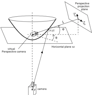
Some mirror shapes when used with certain types of lenses result in an omnidirectional vision system with a single center of projection propriety, also called single effective viewpoint propriety. For this type of omnidirectional vision system, the light rays responsible for the image formation intersect in the mirror focal point after reflecting at the mirror surface (Fig. 1). This point is the center of projection of the mirror. Baker and Nayar (1998) describe expressions that represent different sets of catadioptric omnidirectional vision system with single center of projection propriety. Basically, there are only two feasible ways of constructing an omnidirectional vision system with this property. One way is using a parabolic mirror with an orthographic projection lens camera. The other is using a hyperbolic mirror with a perspective projection lens camera.
the pixels of the omnidirectional image onto a cylindrical plane around the vision system, as shown in Fig. 1.
F F'
f
Projection plane of the camera
Panoramic image
Perspective image
Figure 1. Creation of perspective and panoramic images by projecting the acquired image into properly defined projection planes.
Nayar (1997) and Peri et al. (1997) describe an omnidirectional vision system implemented with an orthographic projection lens camera and a parabolic mirror. They also describe a software made to visualize images. This software simulates a virtual perspective camera placed in the single center of projection of the camera. The user can adjust the view direction, field of view and magnification of this virtual camera. The perspective image showed by the software is computed at frame rate from the original image acquired by the implemented omnidirectional vision system.
Svoboda et al. (1997) implemented a catadioptric vision system with single center of projection using a perspective projection lens camera and a hyperbolic mirror. Svoboda et al. (1997) also shows the epipolar curves for this type of system showing that it is possible the use the omnidirectional images acquired by the system to compute distances of objects in the environment based on a stereo vision system.
F
(x,y)
camera
Perspective projection plane
ϕ
vp
up
fp
θ
virtual Perspective camera
Horizontal plane xz
Figure 2. Virtual perspective projection camera at the focus of hyperbole.
In this paper we show an omnidirectional vision system developed by the Laboratory of Advanced Perception at the
Department of Mechatronics Engineering of the Escola Politécnica of the University of São Paulo. The omnidirectional vision system developed was based on the mirror described by Svododa et al. (1997). In this paper we present the formulation used to construct the mirror. Then we show the formulation used to create panoramic and perspective images, as well as, we show how to find the direction of an object in the environment related to the mirror center using the coordinates of the object in the image. We also show how the mirror was manufactured and finally, we show some results and draw some conclusions.
Nomenclature
a = geometric parameter of the hyperbolic mirror, dimensionless
b = geometric parameter of the hyperbolic mirror, dimensionless
D = proportion of the total height of the panoramic image that corresponds to the distance from the top of the image to a line parallel to the ground that cross the focal point of the mirror, dimensionless
e = half of the distance between the focal point of the camera and the focal point of the mirror, m
F = focal point of the camera, m F’ = focal point of the mirror, m f = focal distance of the camera, m
fp = equivalent in pixels of the distance from the focal point of
the mirror to the perspective projection plane, dimensionless Hpn = horizontal size of the panoramic image, dimensionless
h = distance between the focal point of the camera and the top of the mirror, m
ri = radial distance in pixel of a point in the image acquired by
the omnidirectional vision system, dimensionless rpixel = number of pixels of the mirror rim radius in the image,
dimensionless
rtop = radial distance of a point located at the top of the mirror
surface (mirror rim), m
tpixel = size of each pixel element in the CCD of the camera, m
u = horizontal coordinate of a pixel in the image, dimensionless Vpn = vertical size of the panoramic image, dimensionless
v = vertical coordinate of a pixel in the image, dimensionless x = radial coordinate of a point in the mirror surface, m y = height coordinate of a point in the mirror surface, m
Greek Symbols
ϕ = elevation angle of direction, deg.
φ = vertical angle of view of the vision system, deg. θ = azimuthal angle of direction, deg.
Subscripts
p relative to the perspective image
pn relative to the panoramic image
top relative to the point at the mirror surface on the top of the mirror (mirror rim)
0 relative to the direction that defines the perspective projection plane
Hyperbolic Mirror for Omnidirectional Vision System
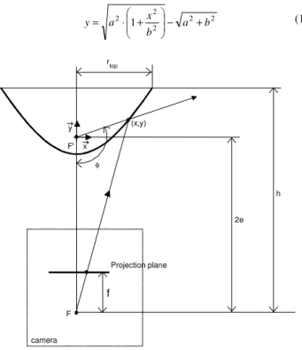
Results. Furthermore, due to the center of projection propriety it is possible to obtain distortion free panoramic and perspective images. A hyperbolic mirror can be defined, as presented in Svoboda et al. (1997), in a coordinate frame centered in the mirror focal point
F’, as shown in Fig. 3, by the following equation, function of the mirror parameters a and b
2 2 2 2
2 1 a b
b x a
y − +
+ ⋅ = (1) F F' x y h 2e f (x,y) φ Projection plane rtop camera
Figure 3. Hyperbolic mirror and camera geometry.
In Fig. 3, h is the distance between the mirror rim and the focal
point of the camera, 2 2
b a
e= + represents the eccentricity of the
mirror, rtop is the coordinate x of the top of the mirror, and
ytop = h− 2e is the coordinate y of the top of the mirror. The
maximum angle of view φ of the mirror is given by
− + + = top r b a
h 2 2 2
arctan 2
π
φ (2)
To specify the equation of the mirror is necessary to define a relationship between the parameters a and b. Inserting the coordinates of the top of the mirror (rtop, ytop) in Eq. (1), we get the
following equation that relates the parameter b in function of the relation a/b
2 2 2
2
1 h rtop
b a b a h
b − ⋅ +
+ ⋅ = (3)
In order to design a compact omnidirectional vision system, which is a desirable characteristic for a system to be embedded in a mobile robot, the values of rtop and h must be set adequately. We
consider that the image of the mirror rim is a circle and not an ellipse, i.e., we consider that the vertical and horizontal scale factors are the same. Then the height h can be computed as a function of the focal distance of the camera (f), the measure in pixels of the mirror rim radius (rpixel) and the measure in millimeters of the size of each
pixel in the camera CCD (tpixel). The following expression relates h
in function of these parameters
pixel pixel top r t r f h ⋅ ⋅ = (4)
The parameters f, tpixel, and rpixel depend on the lens and camera
we are using as well as on the image acquired by the system. To obtain the desired value of h we need to choose the mirror dimension (rtop). Once we have the value of h, we choose a value for
the relation a/b and then find the value of a and b using Eq. (3). Then we can find the mirror equation and the maximum angle of view using Eqs. (1) and (2), respectively. Svoboda et al. (1997) show some mirror shapes and angle of view for some values of a/b.
Omnidirectional Image Unwarping
An omnidirectional vision system maps the environment around it into polar coordinates on the acquired image. Depending on the application it is necessary to transform the acquired image into another image through properly remapping the pixels. This transformation is called image unwarping and it is useful to obtain panoramic images or perspective images from the acquired image. These types of images are more comprehensible to humans. Besides, image processing algorithms designed to work with perspective projection images could be applied if we can obtain perspective images from the omnidirectional image.
In this section we describe three methods of omnidirectional image unwarping. The first one is used to obtain panoramic images through the direct transformation of polar coordinates to rectangular coordinates. The second method is also used to obtain panoramic images, but differently from the first one, this method uses the mirror equation and the single center of projection to obtain panoramic images free of vertical distortions. Finally the third method described can be used to obtain perspective images using the single center of projection propriety. Beside these three unwarping methods, we show how to retrieve the direction of an object relative to the vision system from the image coordinate of this object.
Direct Mapping from Polar Coordinates to Rectangular Coordinates
A panoramic image can be obtained when an image acquired by the catadioptric vision system is mapped from polar coordinates to rectangular coordinates. This can be done when the azimuthal angle in the original image is mapped into the horizontal axis of the panoramic image, and the radial coordinate in the original image is mapped into the vertical axis of the panoramic image, as shown in Fig. 4.
The following equations can be used to generate the panoramic image ⋅ ⋅ = pn pn pn pixel pn H u V r v
u cos 2π (5)
⋅ ⋅ = pn pn pn pixel pn H u V r v
v sen 2π (6)
origin (0, 0) of the coordinate system in the original image is placed at the center of the image, and the origin of the coordinate system in the panoramic image is placed at the left-top corner as shown in Fig.
4. The radial coordinate in pixels of the mirror rim in the original image is rpixel, and the height and width of the panoramic image are
defined as Vpn and Hpn.
Image acquired by the mnidirectional vision system
Panoramic image resultant of the unwarping process Image region with
environment information
u u v
v u
pn pn
Figure 4. Example of unwarping process to obtain a panoramic image.
A pixel in the original omnidirectional image can be mapped to more than one pixel in the panoramic image. For this reason an inverse mapping is done, i.e., for each pixel in the panoramic image we find a correspondent pixel in the image acquired by the omnidirectional vision system using the given equations. This guarantees that every pixel in the created panoramic image will be filled.
The image unwarping can be done in real-time using a lookup table. This lookup table stores the correspondence between the pixels in the unwarped image and the pixels in the image acquired by the system. Once this correspondence relation is computed by Eq. (5) and (6), this relation is stored in the lookup table so that this computation does not need to be done for each image acquired.
Image Unwarping Using the Single Center of Projection.
In the omnidirectional image formation process, depending on the mirror type used, the environment is mapped to the image plane through a non-linear polar mapping. For this reason, non-linear distortions related to the mirror geometry can be observed in the radial direction of the acquired image. In this case, when the image unwarping method presented on the last section is applied, we can expect to see distortions in the vertical direction of the panoramic images generated. These distortions can be eliminated if the mirror equation is used in the unwarping process.
The omnidirectional vision system composed by the hyperbolic mirror and a perspective camera has the single center of projection propriety. The single center of projection is the point where the light rays that compose the image intersect each other after reflected by the mirror. For practical purposes, it is as if we could see the environment in all directions from that single point. Using this propriety with the mirror equation, it is possible to get panoramic images by mapping the image pixels into a cylindrical plane around the vision system (Fig. 1), eliminating the distortion introduced by the mirror shape.
Figure 5 shows how the pixels in a radius of the acquired image can be mapped to a column of the panoramic image. In this
unwarping method, we consider the hyperbolic mirror geometry and the single center of projection to map the pixels.
In Fig. 5, vpn represents the coordinate of a pixel in a column of
the panoramic image and vpn = 0 for pixels that correspond to the
mirror rim. The parameter ri represents the radial distance of a pixel
in the omnidirectional image. The coordinate (x, y) represents a point on the mirror surface. The user defined parameter D.Vpn
represents the height in the panoramic image measured in pixels from the horizontal line that corresponds to the mirror rim, x = rtop,
until the horizontal line that corresponds to y = 0. The remaining parameters, mirror eccentricity 2e, rpixel, ytop and rtop, are known.
F F'
DV v
2e
f
(x,y)
ϕ
ψ
ri
Projetion plane of the camera
cilindric projection plane used
to create panoramic image y
x
pn pn
vpn
The following expressions can be derived from trigonometric relations observed in Fig. 5
(
)
top pn top pn pn r V D y v V D x y ⋅ ⋅ ⋅ − ⋅ ⋅= (7)
(
)
(
pn pn)
top pn toptop pixel pn i r e V D y x v V D y e r V D x r ⋅ ⋅ ⋅ + ⋅ ⋅ − ⋅ + ⋅ ⋅ ⋅ ⋅ = 2 2 (8)
The Eq. (7) represents a line that passes through the focal point of the hyperbole and through vpn. For a given value of vpn, we make
Eq. (7) equal to Eq. (1) and find the root of the polynomium using the Newton’s numeric method. Then we find the x value for which the line intersects the mirror surface. Replacing this x value in Eq. (8), we get the radial distance ri of a pixel in the original image
that corresponds to a pixel in the panoramic image with vertical coordinate vpn.
Similarly to the unwarping method presented in the previous section, the panoramic image is created by doing an inverse mapping of the pixels, i.e., for each pixel in the panoramic image we search for its correspondent in the image acquired by the vision system.
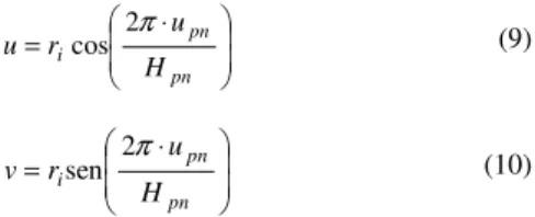
The equations presented so far in this section can be used to do the inverse mapping of a column in the panoramic image to a radial line in the original image, as shown in Fig. 4. Eqs. (9) and (10) extend this mapping process to the rest of the omnidirectional image. In these equations, upn represents the column in the
panoramic image that is being mapped; ri is the value given by
Eq. (8) in function of vpn. The parameters u and v represent the
coordinate of a pixel in the image acquired by the vision system that corresponds to the pixel with coordinates (upn, vpn) in the panoramic
image. In Eqs. (9) and (10) we consider that the position (0, 0) in the acquired image is located in the center of the image.
⋅ = pn pn i H u r
u cos 2π (9)
⋅ = pn pn i H u r
v sen 2π (10)
This unwarping method can be implemented to obtain panoramic images in real time using lookup tables. At the initialization, the iterative numerical method of Newton is used only once to find the correspondence of each pixel in the panoramic image to a pixel in the omnidirectional image acquired by the system. Then this correspondence between pixels is stored in a lookup table that can be accessed to unwarp images at real time.
Omnidirectional Image Unwarping for Generating Perspective Images
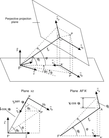
Perspective images can be created from the omnidirectional image acquired by the omnidirectional vision system using the single center of projection. In the vision system constructed with a hyperbolic mirror, the single center of projection lies in the focal point of hyperbole F’. We can define a projection plane that is perpendicular to a line that crosses the focal point of the hyperbole. Then we can map the pixels of the omnidirectional image onto that plane (Fig. 2). The images created by this unwarping process are equivalent to images acquired by a virtual perspective camera with its focal point placed in the focal point of the hyperbole.
A perspective projection plane can be defined by (fp, θ0, ϕ0),
where fp represents the distance in pixels from the focal point of the
hyperbole to the defined plan, θ0 represents the azimuthal angle of
direction of the plane, and ϕ0 represents the elevation angle of the
plane as shown in Fig. 6. If we could relate these parameters with a virtual perspective camera mounted on a pan/tilt mechanism, fp
would represent the focal distance of the virtual camera, and θ0 and
ϕ0 would be the pan and tilt angles respectively.
F F' 2e f (x,y) Camera projection plane r top camera θ Perspective projection plane F' ϕ Mirror rim vp up B A
View from A
View from B y
x
plano de projeção perspectiva x z up Perspective projection plane vp fp fp
up
up vp
z θ0 θ
ϕ0 ϕ
P A' P' F' y x
v 'p
P' up
θ0
θ0
θ
f cosϕ v senϕ
f u x z F' A' ϕ0
Plane xz p p p p 0 0 A fp v ' A' F' vp ϕ ϕ0 p v 'p
v pcosϕ 0
Plane AF'A'
Perpective projection plane
Figure 7. Geometric relations used to create perspective images.
The coordinate of a pixel in the perspective plan (up, vp) can be
related to the direction (θ, ϕ) of a light ray that arrives in the camera sensor and it is responsible for the formation of a pixel in the omnidirectional image. This correspondence can be described by geometric relations, as shown in Fig. 7, and is presented by the following equations 0 0 0 cos cos sen tan ϕ ϕ ϕ ϕ p p p f v f + = (11)
(
)
(
0 0)
0 00 0 0 0 sen cos sen cos cos sen sen cos tan θ θ ϕ ϕ θ θ ϕ ϕ θ p p p p p p u v f u v f + ⋅ − − ⋅ − = (12)
For a given light ray with elevation angle ϕ, it is possible to find a point (x, y) in the mirror surface where the light ray is reflected by solving the mirror equation (Eq. 1) for y = x . tan ϕ. Once we find the point (x, y) in the mirror surface, the pixel (u, v) in the image acquired by the camera that corresponds to the light ray defined by the angles of direction (θ, ϕ) can be found by the following equations:
(
)
(
tanϕ 2)
cosθ2 e x r y e x
u top pixel
+ ⋅ ⋅ + ⋅ = (13)
(
)
(
tanϕ 2)
senθ2 e x r y e x
v top pixel
+ ⋅ ⋅ + ⋅ = (14)
In order to create a perspective image from the image acquired by the omnidirectional vision system, we must firstly define the direction and distance of the perspective projection plane (fp, θ0, ϕ0).
The parameter fp defines the zoom of the perspective image. For
each pixel (up, vp) of the projection plane, we use Eqs. (11) and (12)
to find the direction (θ, ϕ) of a light ray that cross the focal point of the hyperbole and also cross the pixel (up, vp). Then we solve the
mirror equation (Eq. 1) for y = x . tan ϕ. Finally, with the coordinates of the point (x, y) in the mirror surface, using Eq. (13) and Eq. (14) we find the pixel (u, v) in the omnidirectional image that corresponds to the pixel (up, vp) in the perspective image.
Although the point (x, y) can be found using an iterative numerical method, it is possible to create the perspective images at real time using a lookup table. This lookup table relates every pixel (u, v) in the omnidirectional image to the correspondent direction angles (θ, ϕ). Then when a perspective plane (fp, θ0, ϕ0) is defined,
each pixel (up, vp) in the perspective image can be related at real
time to a pixel (u, v) in the acquired omnidirectional image. This is done using the lookup table, Eq. (11) and Eq. (12).
Retrieving Object Direction from Pixel Coordinates in the Omnidirectional Image
The center of projection propriety can also be used to find the angles of direction (θ, ϕ) of any object represented in the image. A pixel coordinate in the omnidirectional image can be represented by (u, v), where (u = 0, v = 0) is located at the center of the image. The azimuthal angle and the elevation angle of the light ray that reaches the imaging sensor at the position (u, v) is given respectively by θ = arctan (v/u) and ϕ = arctan (y/x). The point (x, y) located at the mirror surface where the light ray is reflected can be found by solving the mirror equation for y given by the following equation:
e v u x f y 2 2 2+ −
⋅
= (15)
Omnidirectional Vision System
The omnidirectional vision system implemented is composed by a camera with perspective projection lens (conventional camera and lens), a mirror, and fixation parts that hold the mirror and camera in the right position, as shown in Fig. 11.
Camera
The camera used in the vision system is a monochrome industrial camera with 1/2’’ CCD. According to the manufacturer the scanning area is 6.45 mm (H) x 4.84 mm (V), and the video standard is EIA (30 frames per seconds), the effective number of pixels is 768 (H) x 494 (V). Despite this effective number of pixels, we acquire images with size 640 (H) x 480 (V) pixels at 30 frames per seconds.
Lens
A conventional perspective lens was used in the camera. The lens has a variable focal distance which ranges from 6 to 12 mm, and it was manually set to 12 mm. In the implemented omnidirectional vision system, a spacer ring of height 1.5 mm was used between the camera and the lens in order to get the image in focus at the distance being used between the camera and the mirror.
Hyperbolic Mirror
approximate parameters: f = 12 mm and tpixel = 0.01 mm. The image
acquired by the camera is 640 x 480 pixels. We want that the mirror rim in the image have a radial dimension of rpixel = 240 pixels.
Finally, in order to get a compact system, we chose the radial dimension of the mirror as being rtop = 20 mm. Replacing these
values into Eq. (4), we get the distance between the focal point of the camera and the mirror rim, h = 100 mm.
Based on an analysis presented in Svoboda et al. (1997) that shows the variation of the maximum field of view and the shape of the mirror in function of the relation a/b, we chose to machine a mirror with the relation a = 2b. Then, using Eqs. (3) and (2) we obtained the following mirror parameters: b = 19.646, a = 39.292, and α = 121.3°. Replacing a and b values into Eq. (1), we obtained the final mirror equation for a frame centered on the mirror focal point F’
9 . 43 186 1 3 . 39
2 −
+
= x
y (16)
Once the mirror shape equation is specified, it is possible to machine the mirror from a cylinder of aluminum using a CNC lathe to machine the aluminum to the desired shape and then polish the surface to make it reflexive as a mirror. Also, besides polishing the surface, a coat of nickel or chrome can be applied to the surface to improve the mirror reflective properties. These methods were used to manufacture the mirrors described in Chahl; Sirinivasan (1997), Hicks; Bajcsy (1999), and Ishiguro (1998).
The Mechanical Engineering Department of the USP in São Carlos has an ultraprecision CNC lathe. This lathe can give to the machined surface the same finishing as a polish surface, resulting in a surface with mirror characteristics. The use of an ultra-precision CNC lathe produces a high quality mirror surface that does not requires any manual polishing or the deposit of a nickel or chrome coating to improve the reflective properties of the mirror surface. Another reason not to apply a manual polishing and a coating over the surface is that these processes can introduce some errors in the mirror shape.
The hyperbolic mirror used in this project was manufactured using aluminum in two steps: (1) using a conventional lathe machine we give the aluminum piece a shape close to the desired shape of the mirror and (2) using the ultra-precision CNC lathe we achieved the final shape and finishing of the surface with mirror quality. After this, the surface was already reflexive and could be directly used in the vision system. To avoid scratches on the surface, a thin coating of rock crystal could be applied to the surface. This coating was not applied to the manufactured mirror, so an acrylic cylinder was used in the omnidirectional vision system to confine the mirror and keep it safe from scratches.
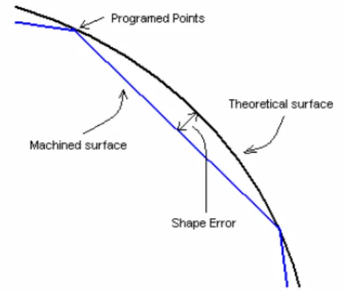
Figure 8. Shape error after machining.
In order to machine the mirror surface using the ultra-precision lathe, we had to properly choose the points to be programmed on the lathe. The actual machined surface is formed by the linear interpolation of the programmed points. The difference between the theoretical and the actual machined curve is called shape error, and it is illustrated in Fig. 8. In order to keep this error within an acceptable value that produces a mirror surface that represents accurately the equation, a minimum number of points must be determined so that only the necessary points are programmed in the CNC lathe.
We used the method described by Palma and Porto (1995) to compute the coordinates of the points to be programmed into the lathe that would keep the shape error within a desired limit. We also compensated the tool radius when computing the position of the points. This compensation is required because during the machining process the point of contact between the tool and the aluminum is not always at the apex of the tool which is used to zero the coordinates of the CNC lathe, as shown in Fig. 9.
Figure 9. Trajectory of the tip of the tool during the machining of the mirror.
Figure 10 (a) shows the manufactured hyperbolic mirror made of aluminum with 40 mm of diameter.
Spherical Mirror
Besides the hyperbolic mirror, a spherical mirror was also manufactured. This was done in order to compare the images acquired using the hyperbolic mirror with the images acquired using the spherical mirror.
When a catadioptric ominidirectional vision system is used in a mobile robot with the camera pointed up to observe the ground of the environment reflected on the mirror, the reflection of the camera and the robot on the mirror appears in the center of the image. The greater the mirror and the further it is placed from the camera, the smaller is the region in the image that is occupied by the reflection of the robot. However, usually we desire that the omnidirectional vision system for the mobile robot be compact when compared to the robot dimensions.
In order to specify the size of the spherical mirror, we considered the maximum size that the vision system could have. With this limitation in mind, we choose diameter of 70 mm for the spherical mirror. Then the approximate distance between the focal distance of the camera and the top of the mirror can be computed
using Eq. (4). Considering the parameters f = 12 mm,
tpixel = 0.01 mm, rpixel = 240, and rtop = 70 mm, we obtained
410 mm. For comparison purposes, our robot has a cylindrical format with 310 mm of height, and 300 mm of diameter.
The spherical mirror was manufactured by applying a reflexive metal coat to the inner surface (concave side) of a semi-spherical glass dome. The manufactured spherical mirror has some irregularities at the apex of the mirror due to the fabrication process of the dome, which does not affect the planned robot application because this is exactly the part of the mirror reflecting the camera itself and does not contain useful information. Also we could not guarantee at the manufacturing process the precision of shape of the glass. However, the images acquired using this mirror were accurate enough for the purposes of this work. A better image result though could be achieved with the same semi-spherical glass if we had put the reflexive metal coat at the exterior surface of the glass. Then, the light would reflect only once at the mirror instead of reflecting partially at the glass surface as well.
(a) (b)
Figure 10. Convex mirrors built. (a) Hyperbolic mirror with 40 mm of diameter machined on aluminum by an ultraprecision CNC lathe. (b) Spherical mirror with 70 mm of diameter built using glass.
Figure 10 (b) shows the spherical mirror with 70 mm of diameter manufactured using glass.
Parts for Fixation
In order to hold the mirror at the defined height from the camera we used a transparent acrylic cylinder. Using this transparent cylinder we avoid occlusions of the environment by the mirror support.
We have notice that inside the lab, where there are only artificial sources of light, there were no significant interference of the acrylic on the quality of the image acquired by the vision system. The eventual reflection of light in the cylinder did not significantly alter the image.
We also made several aluminum parts: part to mount the omnidirectional vision system on the mobile robot; parts to mount the camera at the vertical position and part to mount the mirror on the acrylic cylinder. The camera and the mirror where mounted in such way that the optical axis of the camera is aligned with the axis of symmetry of the mirror.
The final height of the omnidirectional vision system prototype that uses the hyperbolic mirror was 285 mm. The final height of the omnidirectional vision system prototype that uses the spherical mirror was 410 mm. If a smaller camera were used, the height of both vision systems could be reduced.
Figure 11 shows the mobile robot with the omnidirectional vision system using the hyperbolic mirror.
Results
The omnidirectional vision system prototype was mounted on the robot and some tests with the hyperbolic and with the spherical mirror were made. The image unwarping methods were implemented and applied to images acquired by the vision system.
Figure 12 (a) shows an image acquired by the omnidirectional vision system using the spherical mirror. Figure 13 shows this image unwarped by the method that applies a linear transformation between a radial line in the omnidirectional image and a vertical line in the panoramic image.
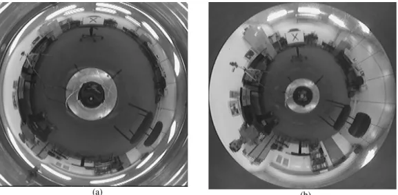
Figure 12 (b) shows an image acquired by the omnidirectinal vision system using the hyperbolic mirror. Figure 14 shows the acquired image unwarped by the method that uses the mirror equation to map pixels in a radial line of the omnidirectional image to a vertical line in the panoramic image. Figure 15 shows the acquired image unwarped by the method that applies a linear transformation between a radial line in the omnidirectional image and a vertical line in the panoramic image.
Both images in Fig. 12 were acquired keeping objects in the environment at the same position. So we can compare qualitatively both images.
(a)
(b)
(a) (b)
Figure 12. Images acquired by the omnidirectional vision system. (a) Image acquired using the spherical mirror;(b) Image acquired using the hyperbolic mirror.
Figure 13. Panoramic image created by a direct mapping of the pixels of the image acquired by the spherical mirror.
Figure 14. Panoramic image created using the hyperbolic mirror equation and the single center of projection to compensate the mirror shape distortion of the image acquired by a hyperbolic mirror.
Looking at the image acquired by the omnidirectional vision system that uses the spherical mirror, Fig.12 (a), we can see that objects near the rim of the mirror are represented by less pixels than the same objects in the image acquired by the omnidirectional system that uses the hyperbolic mirror, Fig.12 (b). Due to the mirror shape, the objects in the images acquired using the spherical mirror have low resolution near the border of the mirror (Derrien; Konolige, 2000). This same result can be observed when we compare Fig. 13 and Fig. 15. These images correspond to the result of the unwarping process using the same unwarping method applied to the images acquired by each one of the mirrors.
Figures 14 and 15 were obtained through different unwarping process applied to the same omnidirectional image acquired with the hyperbolic mirror. Comparing these two images, we can see that in Fig. 15 the aspect of the person in the center of the image and the aspect of the chair at left were not much distorted as in Fig. 14. The
distortions due to the shape of the mirror were removed in Fig.15. The remaining distortions were due to the perspective view and due to the horizontal distortions typical of a panoramic image. We can see that when the hyperbolic mirror equation is used together with the single center of projection propriety we can obtain panoramic images free of the mirror shape distortions.
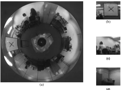
The uwarping method to obtain perspective images were also implemented and Fig. 16 shows an omnidirectional image acquired by the vision system and some perspective images obtained from it.
The perspective images were obtained by defining the angles of direction of the perspective projection plane and by defining a focal distance in pixels that represents the distance between the projection plane and the focal point of the mirror. The value of this focal distance used to obtain the perspective images shown in Fig. 16 were 170 pixels. Modifying this value we can zoom the perspective image.
(b)
(c)
(a)
(d)
Figure 16. Perspective images (b), (c) and (d) created from the omnidirectional image (a).
In order to implement the unwarping methods that use the mirror equation to compensate for distortion, we used an iterative numerical method to solve an equation to find the correspondence between the pixels in the unwarped image and the pixels in the image acquired by the vision system. This iterative method takes a computational time that prohibits its use at real time. However using lookup tables it is possible to implement the unwarping methods to generate panoramic and perspective images at real time. The correspondence between the pixels are computed using the iterative numeric method to solve the equation only once at the initialization. Then this correspondence between the pixels is stored in a lookup table that is used to generate the panoramic or perspective images at real time. The implementation of the unwarping process works at a frequency rate higher than the image acquisition frequency rate. This means that all the frames acquired are unwarped.
In tests where the real time unwarping methods were executed, we obtained an updating frequency of average 46.1 Hz for panoramic images generated with size 800 (H) x 240 (V) pixels. The average updating frequency for perspective images generated with size 128 (H) x 96 (V) we obtained an updating frequency of 95.8 Hz. At startup, the average time required to compute the lookup table of size 800 x 240 used to generate the panoramic images was 2.9 seconds. The average time required to compute the lookup table
of size 1440 x 484 used to generate the perspective images were 12.1 seconds.
The lookup table used in the unwarping process to generate perspective images relates the azimuthal and elevation angles with the pixels of the acquired image. For a lookup table of size 1440 x 484 we used 1440 points to map the azimuthal angles that varies from 0 to 360o and 484 points to map the elevation angles that varies
from 31o to –90o (see Fig. 6). Then, the lookup table has a resolution
of 0.25o for each one of the direction angles. It is interesting to note
that once this lookup table is computed we can change the direction angles of the perspective projection plane at real time and still continue to get perspective images at real time.
The unwarping algorithms were implemented to evaluate the quality of the mirrors, to validate the methodology used to construct the mirrors, and to verify the single center of projection propriety of the hyperbolic mirror.
Conclusion
the vision system that uses a hyperbolic mirror is 285 mm. It could be possible to reduce this size if a smaller camera were used.
A spherical mirror was made by adding a coat of metal to the inner surface of a semi-spherical glass dome. A hyperbolic mirror was manufactured by machining aluminum in an ultraprecision CNC lathe. This was made at the Mechanical Engineering Department of USP in São Carlos.
Different image unwarping algorithms were implemented, including some that use the single center of projection propriety of the hyperbolic mirror. The implemented algorithms allow us to generate panoramic and perspective images at real-time from the omnidirectional image. The panoramic image is generated when mapping the pixels of the acquired image into a cylindrical plane around the vision system. A perspective image can be generated when the pixels of the acquired image are mapped into a plane defined at a given direction and distance from the system. These real-time perspective images simulate a virtual camera placed at the single center of projection with the same functionality that a camera mounted on a pan/tilt mechanism has.
We presented some examples of the acquired images by the omnidirectional vision system and some results from the different image unwarping methods implemented.
The omnidirectional vision system develop is planned to be used in real time mobile robot applications such as navigation and visual servo control, among others. The property of having a single center of projection and the capability of acquiring images with a large field of view at real time are important features to be used in the planned robot tasks.
Acknowledgements
This work was partially supported by FAPESP and RECOPE. We are also grateful to the NUMA (Núcleo de Manufatura Avançada) of the Mechanical Engineering Department of USP at São Carlos for the human resources and equipment that were essentials to machine the hyperbolic mirror, particularly to Professor Arthur Vieira Porto. We also acknowledge Roberto Verzini from Engefilm Ind. and Com. Ltda. for coating the semi-spherical glass to make the spherical mirror, and Adilson Fernandes Felix Filho for machining the support parts of the omnidirectional vision system.
References
Baker, S., Nayar, S.K., 1998, “A Theory of Catadioptric Image Formation”, Proceedings of the 6th International Conference on Computer Vision, pp. 35-42, Bombay, India.
Cao, Z.L., Oh, S.J., Hall, E.L., 1985, “Dynamic Omnidirectional Vision for Mobile Robots”, Proc. SPIE Intelligent Robots and Computer Vision, Vol. 579, pp. 405-414.
Chahl, J.S., Srinivasan, M.V., 1997, “Reflective Surfaces for Panoramic Imaging", Applied Optics, Vol. 36, No. 31, pp. 8275-8285.
Chang, P., Hebert, M, 1998, “Omni-directional Visual Servoing for Human-Robot interaction”, Proc. of IEEE/RSJ International Conference on Intelligent Robotic Systems (IROS),Victoria, B.C., Canada.
Das, A. K., Fierro, R., Kumar, V., Southall, B., Spletzer, J., Taylor, C. J, 2001, "Real-time vision based control of a nonholonomic mobile robot," IEEE Int. Conf. on Robotics and Automation, Seoul, Korea, pp. 1714-1719.
Das, A. K.; Fierro, R.; Kumar, V.; Ostrowski, J. P.; Spletzer, J.; Taylor, C. J., 2002, "A vision-based formation control framework," IEEE Trans. Robotics and Automation, vol. 18, no. 5, pp. 813-825.
Gaspar, J.; Winters, N.; Santos-Victor, J, 2000, “Vision-based Navigation and Environmental Representations with an Omni-directional Camera”, IEEE Transactions on Robotics and Automation, v.16, n.6, p.890 -898.
Hicks, A., Bajcsy, R., 1999, “Reflective Surfaces as Computational Sensors”, Workshop on Perception for Mobile Agents at CVPR’99, Fort Collins, Colorado, USA.
Nayar, S.K., 1997, “Catadioptric Omnidirectional Camera”, Proc. of IEEE Conference on Computer Vision and Pattern Recognition (CVPR), pp. 482-488.
Palma, J.G., Porto, A.J.V., 1995, “Sistema de Apoio a Programação Comando Numérico para Usinagem de Ultraprecisão”, Dissertação de mestrado, Escola de Engenharia de São Carlos da USP, São Carlos.
Peri, V.N., Nayar, S.K., 1997, “Generation of Perspective and Panoramic Video from Omnidirectional Video”, Proc. of DARPA Image Understanding Workshop, pp. 243-245.
Svoboda, T., Pajdla, T., Hlavac, V., 1997, “Central Panoramic Cameras: Geometry and Design”, Research Report K335/97/147, Czech Technical University, Faculty of Electrical Engineering, Center for Machine Perception, avaiable at ftp://cmp.felk.cvut.cz/pub/cmp/articles/svoboda/TR-K335-97-147.ps.gz
Yagi, Y., Kawato, S., Tsuji, S., 1994, “Real-Time Omnidirectional Image Sensor (COPIS) for Vision-Guided Navigation”, IEEE Transactions on Robotics and Automation, Vol. 10, No. 1, pp. 11-22.