1Dr. Ing, Emeritus Professor, Department of Metallurgical Engineering and Materials, Federal University of Minas Gerais – UFMG,
Av. Antonio Carlos, 6627, CEP 31270-901, Belo Horizonte, MG, Brazil. E-mail: [email protected]
2PhD. Associate Professor, Department of Materials Engineering, Federal University of Ouro Preto – UFOP, Campus do Morro do Cruzeiro,
Escola de Minas, Bauxita, CEP 354000-000, Ouro Preto, Minas Gerais, Brazil. E-mail: [email protected]
3DSc. Associate Professor , Department of Materials Engineering, Federal University of Ouro Preto – UFOP, Campus do Morro do Cruzeiro,
Escola de Minas, Bauxita, CEP 354000-000, Ouro Preto, Minas Gerais, Brazil. E-mail: [email protected]
4MSc, Avenida Rita Maria Ferreira, 855, apto 504, Prédio Estados Unidos, Bairro Comercial, CEP 27510-060, Resende, RJ, Brazil.
E-mail: [email protected]
A PHYSICAL MODELLING STUDY OF INCLUSION REMOVAL IN
TUNDISH USING INERT GAS CURTAIN
Varadarajan Seshadri 1 Carlos Antônio da Silva 2 Itavahn Alves da Silva 3 Ely da Silva Araújo Júnior 4 Abstract
The control and minimization of non-metallic inclusions content in the tundish and in the mold of a continuous casting unit is crucial for ensuring the final quality of the steel cast product. Nonmetallic inclusions of sizes smaller than 15 µm are hard to remove, as they are difficult to float. They are easily carried by the flow of steel melt into the mold and adversely affect the steel cleanliness. It is suggested that a gas curtain made of small bubbles of argon can be used to capture and remove these inclusions in the tundish, thus avoiding their transport into the mold. A 1:3 scale physical model of tundish of the continuous casting unit of ArcelorMittal plant, in Vitória, Brazil, was built to investigate the effects of gas flow, shape and positioning of the gas curtain inside the tundish, on the efficiency of removal of inclusions. The results suggest that the gas bubbling inside the tundish can be effective in inclusion removal. The efficiency is dependent upon the location of argon bubbling.
Key words: Modelling; Inclusion removal; Tundish.
1 INTRODUCTION
The tundish of the continuous casting machine performs many complex functions. It serves as reservoir, distributor of liquid steel to the strands controlling flows, especially during the transitional arrangements, promotes thermal homogeneity, thermal insulation, composi-tion control of liquid steel enabling addicomposi-tion of alloying elements, prevention of reoxidation by air, coalescence, flotation and removal of non-metallic inclusions etc.
The rate of contamination of the liquid steel in the tundish can be controlled by the adoption of some impor-tant operational practices, such as slag cover, efficient sealing, protection of jet from ladle from oxidation, inhi-bition of vortices, complete flux covering of the surface of the metal with quick formation of a tundish slag with low contents of FeO, and MnO.
The practice of bubbling inert gas in the ladle or in tundish, prior to continuous casting,(1-8) improves the rates of collision and agglomeration of inclusions increasing the rate of flotation of inclusions by the colony of bubbles and formation of clusters of larger sizes. The high degree of turbulence prevailing inside the valve and the good rate
of mixing of liquid steel promote the generation of a zone of finely dispersed bubbles, providing better chances of collision coalescence and capture of non-metallic inclu-sions and greater ability to absorb gaseous impurities. Results from physical modelling, according to Wang, Lee and Hayes,(7,8) indicate the existence of a zone of finely dispersed bubbles, especially when the injection of inert gas is carried out through a partially open valve because of the high state of turbulence. The results also showed that the formation of vortex favoured the formation of fine bubbles with diameters from 0.3 mm to 0.5 mm, and a uniform distribution of bubbles around the jet from the ladle, favouring the capture and removal of inclusions.
= λ m p, p p u 1 u (5) and ∆ρ η = =
∆ρ η λ
m 2 p
p, p,(m) m L
p 2 m
p
p p,(p ) L
u r ( ) 1
( )
u r (6)
If the kinematic viscosity of liquids in model and prototype (water and steel) are considered equal one can write (Equations 7 and 8):
ρ
−
ρ
ν
=
λ ρ ν
−
ρ
1/2 p m L
p(m) p L
1/ 4 p
p(p ) p L
L m 1 r 1 r 1 (7) or −
ρ
−
ρ
= λ
ρ
−
ρ
p
L
p(m) p 1/ 4
p(p ) p
L m 1 r r 1 (8)
Flow of argon and air in the prototype and model can be related on the basis of modified Froude number (Fr’) as a criterion of similarity. If ρg stands for gas density, ug for gas superficial velocity and H for liquid level inside the tundish then (Equation 9),
ρ ρ
= =
ρ ρ
2 2
g g g g
'
m p
L L
u u
Fr [ ] [ ]
g H g H (9)
The superficial gas velocity at the exit of each orifice for bubbling of argon is given by (Equation 10):
= π g 2 O O 4 Q u
d N (10)
where: Q is the gas flow rate, do, the size of each orifice and No the number of orifices. Using this in the modified Froude criteria (Equation 11):
ρ ρ
=
ρ π ρ π
2 2
g g
m p
2 2 4 2 2 4
L O O L O O
16 Q 16 Q
[ ] [ ]
g H N d g H N d (11)
Finally, assuming that the number of orifices are same for the injection of gas in the model and the proto-type (Equations 12 and 13):
ρ ρ = ρ ρ 2 2 g g m p
2 4 2 4
L O O L O O
Q Q
[ ] [ ]
H N d H N d (12)
the reoxidation of the metal bath, and the absorption of nitrogen. If all these factors are taken in consideration inert gas injection can be used as a means of promoting steel cleanness.
This work deals with the evaluation of the effect on the efficiency of flotation of inclusions inside a tundish as influenced by variables such as inert gas injection flow rate, porous plug superficial area and position for injection and other variables, simulating the conditions of tundish of ArcelorMittal Tubarão #2 continuous casting unit. With this objective, a physical model was constructed and operated in the laboratory, considering the tundish geometry as well as operational parameters from the industrial installation.
2 PHYSICAL MODELLING OF RISE OF INCLUSIONS IN THE TUNDISH
For the range of sizes of inclusions in the tundish, one can assume that they float inside the steel with a terminal velocity that can be evaluated by Stokes law. Accordingly, the terminal velocity of particles in the model (m) and prototype (p) can be given as (Equations 1 and 2):
(
ρ − ρ)
=
η
2 m m
p,(m) L p
m p, m L 2r g u 9 (1) and
(
ρ − ρ)
=
η
2 p p
p(p ) L p
p p p L 2r g u 9 (2)
Here, up stands for inclusion velocity, rp for radius of the inclusion, g for gravity acceleration, ρL and ρp for liquid and inclusion densities, respectively, and η stands for liquid viscosity.
Also, using similarity criteria of Froude, the liquid velocities, uL, are related by (Equation 3),
= λ m L p L u u (3)
where λ is the scale factor. For kinematic similarity for the distribution of velocities and the trajectories of particles in the model and the prototype the following criteria for the model and prototype can be applied (Equation 4):
=
L L
p m p p
u u
u u (4)
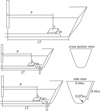
As can be seen from Figure 1, the tundish model feeds 2 strands (or 2 molds). Inclusion flotation efficiency can be assessed by comparing the results obtained for the two strands. One of them is operated without gas injection and air is injected in the other one ( simulating inert gas in the prototype). The industrial tundish has a working volume for 60 tons with a casting capacity of 9 tons/minute. On the basis of similarity criteria discussed in the previous section, Froude number can be used to assess the water flow rate and other parameters on the basis of similarity criteria. Plastic particles (50 to 100 µm and 100 to 200 µm; density of 0.97 g/cm3) were injected at the ladle-tundish nozzle to simulate the pulse of inclusions. These size ranges of plastic particles were arrived at from similarity criteria with inclusions in steel melt, assuming an average inclusion density of 4000 kg/m3 and steel density of 7000 kg/m3. Since the scale factor λ is 1/3, the ratio between actual inclusion size and chosen plastic particle size range yields rm/rp ≈ 6 in accordance with the simila-rity criteria equation for the same given in the previous section. Hence these two ranges simulate inclusions from 10 µm to 15 µm and from 15 µm to 30 µm in the actual tundish of the continuous casting machine. In the experi-ments, a given volume of a particle – water – alcohol pulp was pumped using a peristaltic pump. Metallic sieves with opening of 63 µm (0.063 mm), installed at the two tundish outlets with SEN (Submerged Entry Nozzles), enable the non-floated particles to be captured and weighed for comparison purposes. Thus in a typical experiment of defined process parameters, the weight of particles, captured at the two strands and that of particles skimmed on the top of the liquid, can be evaluated.
To simulate the injection of inert gas through the bottom of the tundish, a system of injection of compressed Hence,
ρ ρ
=
ρ ρ
2 m 4
g O
m L m
p
p L p g m O m
d
Q H
Q d H (13)
Considering geometric similarity between the orifices of model and prototype for injection of gas, one gets (Equations 14 and 15):
ρ ρ
= λ
ρ ρ
2
g 5
m L
p L p g m
Q
Q (14)
or
ρ
ρ
= λ
ρ ρ
g L 5/2
m p
L p g m
Q Q (15)
These are the relations that result from the simi-larity criteria. These have to be taken into consideration, for determining the parameters of the model using the parameters of the prototype for the construction and operation of the physical model.
3 EXPERIMENTAL SET UP AND METHODOLOGY
A 1:3 scale physical model of tundish of Arcelor-Mittal Tubarão #2 continuous casting machine was built and operated under conditions determined on the basis of similarity criteria. The model was built in acrylic, consis-ting of different geometrical aspects of the prototype such as inhibition of turbulence and others such as the Yield Enhancement System.
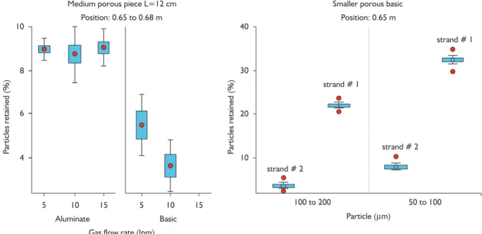
Figure 3 gives the effect of porous piece size, its location in relation to the valve and flow of injected air. It can be observed that, in the case of larger porous piece, the percentage of particles recovered in the sieve located underneath the tundish outlet #2 is relatively lower (the porous plug responsible for additional inclusion flotation is installed at this side of the tundish) and the injection of air with a mass flow meter was provided. A rectangular piece of porous silica-alumina or any other ceramic base material was installed on one side of the strand #2. The two refractory materials used can generate different bubble sizes depending on their grain texture, pore sizes and wettability.
4 RESULTS AND DISCUSSION
Two slightly different experimental set-ups have been provided. The first one is schematically shown in Figure 1. Ceramic materials such as silica-alumina refrac-tory, basic refracrefrac-tory, all of rectangular shape were used to fabricate porous pieces. The width (W) was kept cons-tant whereas the length (L) can vary. The plug location was defined by measuring the distance between the middle of each one to the ceramic nozzle (Figure 2)
gas in general, promotes better particle removal. It is also noticed that with the closeness of the porous plug to the ceramic nozzle, the extent of inclusion removal becomes better. However this effect is smaller when a larger porous piece is employed. These results may be due to the curtain of air that acts as a filter for particles, and its effect on the installation of an upward flow, which is more efficient as it is induced near the entrance of the metal. In this case, the larger piece could be forming a more intense upward flow, diminishing the effect of the position.
In all cases, it can be verified that the flow of air has a negligible effect on results. This suggests the existence of a critical flow rate. Above this critical value, this variable no longer influences the removal of inclusions.
Figure 3. Effect of the size of the porous silicon-alumina plug, its position and air flow rate on the % of particles retained at the side with gas injection.
Figure 4. Percentage of particles collected at the sieve located at the air injection side (all trials), relative to the total amount injected.
The effect of the type of porous material is given in Figure 4. The plug made of basic refractory presents supe-rior performance as compared to silicon-alumina material. This may be due to greater homogeneity of pores in the case of basic refractory, which promotes the formation of more uniform plume made of finer bubbles. Figure 4 suggests that this technique would be more efficient in the case of larger particles as shown by a comparison between strand #2 and strand #1. However, Inclusions with smaller sizes are more likely to be dragged into the mold.
The second experimental set-up employed a ceramic piece around the tundish outlet. This arrange-ment should be more convenient, since there are safety concerns in respect of the tubes for argon injection inserted in the refractory. A shaft made of bubbles arising around the strand outlet may provide a filter or barrier to the entry of inclusions.
As a matter of fact bubbling inert gas around the strand (Figure 5) seems to be effective in inclusion removal. However, it was less effective in comparison with the previously investigated arrangement because of the fact that part of the gas bubbles in the vicinity of the strand was probably dragged into the mold. Increased inert gas flow rate resulted in greater efficiency of capture and removal of inclusions, because of the presence of a larger population of bubbles in the vicinity of gas curtain. However this can give rise to more bubbles dragged into the mold.
According to Thomas and Bai,(5) argon gas flow rate should be about 5 NL/min to avoid clogging since the film of gas formed along the wall of the valve can inhibit the contact between the wall and the inclusions. Also the injected gas may facilitate the capture and flotation of
Figure 5. Effect of blowing air around the tundish outlet #2 (basic refractory).
inclusions in the upper region of the mold and also reduce the aspiration of air. Hence, some drag of bubbles into the mould would not be detrimental.
and
=
+ 0.694
3 Re Y
8 1.736 Re (20)
= 2 b b d u C
u d (21)
and
+ + − +
=
2 2
(X C) 3Y (X C)
D
3Y (22)
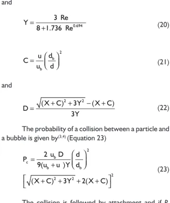
The probability of a collision between a particle and a bubble is given by(3,4) (Equation 23)
= + + + + + 2 b c b b 2 2 2
2 u D d
P
9(u u )Y d
(X C) 3Y 2(X C)
(23)
The collision is followed by attachment and if Pa denotes the probability of attachment then the probability of a successful sequence of collision and attachment would be P = PcPa. As in the case of Rogler(3) and Rogler, Heaslip and Mehrvar,(4) it is assumed, that the process is controlled by collision, namely P~Pc. Now, if n is the number of inclu-sions per unit volume of liquid the rate of inclusion removal by bubbling is given by (Figure 7) (Equations 24 and 25):
= − dn K n dt (24) or −
= K t
e o
n n e (25)
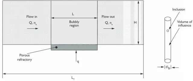
Here no and ne are the number (per unit volume) of inclusions at the entry of the bubbling zone and at the exit of bubbling zone respectively, t is the liquid average resi-dence time inside the bubbling zone; t can be estimated as a fraction of liquid residence time inside the tundish (Equation 26), = τ T L t L (26)
(relevant data for calculating τ are: tundish capacity, 320 liters and volumetric flow rate, 100 Lpm of water). K, the rate constant for the removal process can be estimated as follows. First the number of collecting collisions (colli-sions followed by attachment), Ncc, inside the volume of influence of each bubble is given by(the geometrical para-meters LT, L and H as defined in Figure 7) (Equation 27):
= =
τ
min min
T
T T Q
Fraction of piston flow
V (16)
VT and Q are kept constant throughout these experi-ments and hence Tmin would be the direct measurement of the ability of the tundish in respect of inclusion flota-tion. However, gas injection seems (Figure 6) to decrease the fraction of piston flow. This effect is stronger on the gas injection side. Thus inclusion removal by gas injection cannot be attributed to a more favorable macroscopic flow.
Figure 6. Fraction of piston flow at gas injection side (as measured by the minimum residence time) as a function of gas flow rate.
0 5 10 15
Gas Flow rate (lpm) 40
50 60 70 80
strand # 2; P = 0.65 m aluminate piece
*
* *
* Larger Medium Smaller
Tmin
(s)
*
Some of these results can be anticipated by using a model reported by Rogler.(3) According to this model, if the inclusion diameter is d (plastic particles of 20 × 10–6 m or 40 × 10–6 m) and the bubble diameter is d
b (around 1 × 10⁻³ m, using photographical evidence) their ascension velocities can be estimated by using Stokes law (Equa-tions 17 and 18),
= ρ − ρ
η
2
L d
u g( )
18 (17)
and
= ρ − ρ
η
2 b
b L b
d
u g( )
18 (18)
Here η and ρL are the viscosity and density of the liquid (water, 1 × 10⁻³ Pa.s and 1000 kg.m–3, respecti-vely); g is the acceleration due to gravity,, ρ and ρb are the particle and gas densities (950 kg.m–3 and 1 kg.m–3) respec-tively. Reynolds number for the ascending bubble is given by Re = db ubρL / η, and from its value the following para-meters can be evaluated (Equations 19-22):
= +
+ 0.694
9 Re 3
X
Figure 8 gives the results of variation of efficiency of removal of inclusions with bubble size and inclusion size calculated for the present case.
It can be noticed that there is a strong influence of the bubble size. This effect can be made apparent by comparison of the data for basic and aluminate refractory bubbling elements, represented in Figure 4. The rela-tionship of efficiency of inclusion removal as a function of gas flow rate is almost linear for larger bubble sizes. For larger inclusion sizes, the likelihood of collisions is higher. This results in better efficiency of removal due to bubbles, (Figure 4). However this model does not account for the influence of the length of the bubbling element on the removal efficiency as shown in these experiments. Accor-ding to this model the rate constant of inclusion removal, K, increases for shorter bubbling elements, whereas the residence time of liquid inside the bubbling zone (t) decre-ases. Also the effect of position of the bubbling element on the inclusion removal efficiency is not accounted for.
π
= 2
cc b
N d H n P
4 (27)
The number of bubbles supplied to the liquid, per unit time and unit of bubbling zone, Nb, is given by (Equa-tion 28):
(
)
(
)
= π
b 3 T T
b q
N / V L / L
d / 6 (28)
Here H is the level o liquid inside the tundish (0.43 m); q is the volumetric gas flow rate (corresponding to 0 to 10 Lpm of air); VT is half of the tundish capacity (0.160 m3); L
T is the tundish half length (1.4 m); L is the length of the bubbling zone(0.15 m). Thus the number of collecting collisions per unit volume of bubbling zone would be (Equation 29):
(
)
(
)
π
= =
= π
2
T cc b b
T T
3 b
N N .N d H
4 q
n P / V L / L K n
d / 6
(29)
where the inclusion removal constant is (Equation 30):
(
)
= =
T T
b b b
3 q 3 q
K H P / V L / L P
2 d 2 d A (30)
Here Ab is the area of the bubbling element. The efficiency of inclusion removal (by bubbling) can be defined as (Equation 31)
− −
ε = o e = − K t o
n n
1 e
n (31)
Figure 7. Schematics for bubbling inclusion flotation.
However the orders of magnitude of experimental results and those predicted by this model seem to be in good agreement. Hence the model can be used as a reasonable tool to analyze and improve the industrial system.
5 CONCLUSIONS
Under the experimental conditions investigated with the physical model, the following observations and conclusions can be made:
1) The gas curtain acts as a filter or barrier and promotes an upward flow of liquid favouring separation and removal of inclusions. This effect is more pronounced with the increased proxi-mity of the gas curtain to the ceramic nozzle. 2) For all combinations of flow, position and
dimensions of the porous plug, a reduction of the piston flow fraction resulted in comparison to a tundish without gas injection system.
3) Larger porous plug sizes and larger particle sizes resulted in better flotation and separation; 4) Basic porous blocks seem to be more effective than the acid ones. The reason can be attri-buted to the pore structure and consequent resulting size of bubbles.
5) Bubbling of gas around the strand is also bene-ficial to the inclusion removal. However the efficiency is 25% lower than the one obtained with the porous block.
6) The results of the proposed simplified mathe-matical model for inclusion removal by bubbling are in reasonable conformity with the experi-mental results.
Acknowledgements
The authors wish to thank and acknowledge partial funding by FAPEMIG, CNPq and ArcelorMittal, Brazil.
REFERENCES
1 ZHANG, L.; THOMAS, B. G. State of the art in the control of inclusions during steel ingot casting. Metallurgical and Materials Transactions B, v. 37, n. 5, p. 733-61, 2006. http://dx.doi.org/10.1007/s11663-006-0057-0
2 MIKI, Y.; THOMAS, B. G. Modelling of inclusion removal in the tundish Metallurgical Transactions B, v. 30, n. 4, p. 639-54, 1999.
3 ROGLER, J. P. Modelling of inclusion removal in a tundish by gas bubbling MAS. 2004. 80 p. Thesis (Master of Applied Science) − Ryerson University, Toronto, Canada 2004
4 ROGLER, J. P.; HEASLIP, L. J.; MEHRVAR, M. Inclusion removal in a tundish by gas bubbling. Canadian Metallurgical Quarterly, v. 43, n. 3, p. 407-16, 2004.
5 THOMAS, B. G.; BAI, H. Nozzle clogging tundish: application of computational models. In: PROCESS
TECHNOLOGY DIVISION CONFERENCE PROCEEDINGS, 18., 2001, Baltimore, MD. Proceedings... Warrendale, PA: Iron and Steel Society, p. 895-912.
6 ZHANG, L.; PLUSCHKELL, W.; THOMAS, B. G. Nucleation and growth of Alumina inclusions during deoxidation of steel. In: STEELMAKING CONFERENCE, 85., Nashville, 2002. Proceedings... Warredale: Iron and Steel Society, 2002. p. 463-76.
7 WANG, L.; LEE, H. G.; HAYES, H. A new approach to molten steel refining using fine gas bubbles. ISIJ International, v. 36, n. 1, p. 17-24, 1996. http://dx.doi.org/10.2355/isijinternational.36.17
8 WANG, L.; LEE, H. G.; HAYES, H. Prediction of optimum bubble size for inclusion removal from molten steel by flotation. ISIJ International, v. 36, n. 1, p. 7-16, 1996. http://dx.doi.org/10.2355/isijinternational.36.7