Indirect orthodontic bonding - a modified technique for
improved efficiency and precision
Lincoln Issamu Nojima1, Adriele Silveira Araújo2, Matheus Alves Júnior3
How to cite this article: Nojima LI, Araújo AS, Alves Júnior M. Indirect orth-odontic bonding - a modified technique for improved efficiency and precision. Dental Press J Orthod. 2015 May-June;20(3):109-17.
DOI: http://dx.doi.org/10.1590/2176-9451.20.3.109-117.sar
Submitted: January 20, 2015 Revised and accepted: February 20, 2015 » The authors report no commercial, proprietary or financial interest in the
prod-ucts or companies described in this article.
1 Adjunct Professor, Universidade Federal do Rio de Janeiro (UFRJ), Department
of Orthodontics, Rio de Janeiro, Rio de Janeiro, Brazil.
2 PhD resident of Orthodontics, Universidade Federal do Rio de Janeiro (UFRJ),
Rio de Janeiro, Rio de Janeiro, Brazil.
3 MSc in Orthodontics, Universidade Federal do Rio de Janeiro (UFRJ).
Introduction: The indirect bonding technique optimizes fixed appliance installation at the orthodontic office, en-suring precise bracket positioning, among other advantages. In this laboratory clinical phase, material and methods employed in creating the transfer tray are decisive to accuracy.
Objective: This article describes a simple, efficient and reproducible indirect bonding technique that allows the pro-cedure to be carried out successfully. Variables influencing the orthodontic bonding are analyzed and discussed in order to aid professionals wishing to adopt the indirect bonding technique routinely in their clinical practice.
Keywords:Dental bonding. Orthodontic brackets. Orthodontic devices. Corrective Orthodontics. DOI: http://dx.doi.org/10.1590/2176-9451.20.3.109-117.sar
Contact address: Lincoln Issamu Nojima Av Professor Rodolpho Paulo Rocco, 325 Ilha do Fundão - Rio de Janeiro - RJ - Brazil E-mail: [email protected]
Introdução: a técnica de colagem indireta prioriza a otimização do procedimento de montagem do aparelho fixo na clínica ortodôntica, assegurando, entre outras, vantagens relacionadas à precisão no posicionamento dos braquetes. Nesse procedimento clínico laboratorial, o material e o método de confecção da moldeira de transferência são deter-minantes no quesito precisão.
Objetivo: este artigo descreve uma técnica de colagem indireta simples, eficiente e reprodutível, para que o procedi-mento possa ser realizado com sucesso. Variáveis que exercem influência sobre o procediprocedi-mento são analisadas e discu-tidas, a fim de auxiliar o profissional a adotar, de forma rotineira, a técnica de colagem indireta em sua prática clínica.
stands out for allowing better three-dimensional visualization of tooth positioning and, as a result, greater accuracy while positioning brackets,2 since
the procedure is carried out in the laboratory, fol-lowed by transference to the patient's mouth by means of custom-made trays. This advantage was confirmed by Hodge et al3 who found that errors
associated with bracket positioning were minimized when indirect bonding was chosen over direct bonding, under any of three aspects of observation: height, mesiodistal position and angulation. Better height positioning was also observed by Koo et al,4
while Aguirre et al5 emphasized the higher technical
precision provided by the indirect technique used for brackets angulation on maxillary and mandibular canines and height positioning on maxillary canines.
Other advantages associated with indirect bonding are: (1) reduced chair time,1,2,6 (2) little need
for compensation bends,1 (3) reduced physical and
men-tal stress, since the clinical procedure is simpler than di-rect bonding,1 and (4) more comfort for the patient.6,7
Disadvantages such as time-consuming laboratory procedures and additional costs with material are over-come by the previously stated beneits, which ends up propagating the technique. As a result of the grow-ing popularity of indirect bondgrow-ing, new techniques8
have been developed. These techniques stand out es-pecially on the bonding system applied (self 8 or
light-curing9) and the transfer tray used (hot glue,10
addi-tion silicone,1 vacuum-formed,8 prototyped11 or
as-sociated methods12). Despite the variety of techniques
proposed, indirect bonding is not considered a gold-standard procedure yet, probably due to the numerous variables inherent to the process and which need to be controlled if success is to be obtained.12
The improvement of the technique in order to yield better clinical results is the aim of the various modifications that have been suggested. Assuming the same precept, this article describes a new method
into three stages: Clinical Stage I, Laboratory Stage and Clinical Stage II.
Clinical Stage I
1. Perform dental prophylaxis and upper and lower full-arch impressions with high quality algi-nate, following the manufacturer's instructions. Examine in full detail the impression obtained, in order to avoid potential flaws that may lead to distortions in the dental cast, paying special attention to the areas corresponding to teeth. 2. Obtain dental casts with type IV dental stone.
This procedure should be carried out judicious-ly so that dental casts are free from imperfec-tions (positive and negative bubbles). Surface flaws will hinder brackets and tray fitting to the teeth, when the former are transferred to the oral cavity. It is also necessary to wait for the stone to fully crystallize and dry.
Laboratory Stage
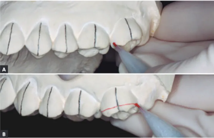
faces, brackets should be placed closer to the occlusal surface of teeth; that is, close to the red line, thus avoiding teeth extrusion, which could compromise treatment results. On the other hand, in deep overbite malocclusions, when ex-trusion of posterior teeth is necessary, brackets should be placed slightly further from the red horizontal line.
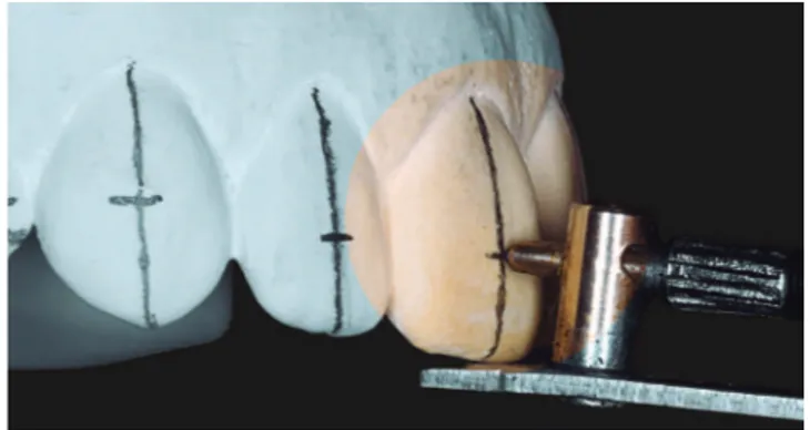
4. With the aid of a drawing compass, determine the distance between the two horizontal lines in the irst molar (Fig 4B) and replicate it on the buccal surfaces of other remaining posterior teeth (Fig 4C), thus establishing bracket slot height (Fig 4D). 5. Calculate and transfer the slot height of incisors
and canines to the cast using a bracket placement marker gauge (Fig 5). Reference tables can be used to determine bracket height of anterior teeth, according to the type of vertical malocclusion. In open bite cases, brackets can be placed more gingival on incisors and canines; whereas in deep bite malocclusions, they can be placed slightly closer to the incisal edges. In most cases, we rec-ommend placing the canine bracket at the same height as the irst premolar, measured from the slot to the cusp tip. For lateral incisors, subtract 1 mm from canines height, and for central incisors, add 0.5 mm to lateral incisors height (Fig 6).
6. Treatment plan should be reviewed with casts in occlusion, and brackets previously selected prior to drawing the guide lines on the lower cast, so as to avoid setbacks during definitive bonding, such as lower brackets interfering in postbonding occlusion.
Figure 1. Long axes of teeth marked in black pencil. Figure 2.A) Mark the mesial and distal marginal ridges with red pencil on buccal surface of teeth. B) Join the marked points, determining the height of marginal ridges.
Figure 3. Marginal ridge heights marked on all posterior teeth.
Figure 4.A) First molar slot height determined in black pencil using a bracket placement marker gauge. B) Measurement of distance between two horizontal lines on the first molar with a drawing compass. C) Reproduction of the same distance on buccal faces of other posterior teeth (blue arrows). D) After joining the marked points, premolars and molars slot heights are determined.
A
B
A
B
C
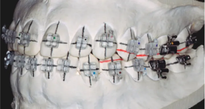
to the bracket base and position it over the cast surface. Follow the previously established bond-ing guide, so that slot and long axis of brackets lie over the drawn guide lines. Press the bracket over the pre-established location and remove excess adhesive (Fig 8). Once all brackets were placed and positions were checked, use a light-curing unit, for example Triad 2000 system (Dentsply, York, PA), to cure the adhesive according to the manufacturer's instructions. Should this type of unit be unavailable, use conventional light-cur-ing devices, directlight-cur-ing the beam towards the me-sial and distal sides of each bracket, for 15 seconds each and at 2 to 3 mm distance.
9. Manufacture the transfer tray. Using a vacuum former, thermoform a 1-mm thick sheet of Ethylene Vinyl Acetate (EVA-foam) (Soft; Bio-Art, São Carlos, SP, Brazil) over the cast. After heated, once the sheet reaches 10 to 12 mm of distortion, according to manufacturer's instruc-tions, it is ready to be formed. Trim excess ma-terial with scissors (Fig 9) and spray a thin layer of silicone over the tray to help separate it later
trim its labial/buccal surface up to the gingival margin of bracket wings, eliminating retention. Use a Scotch Brite brush to finish it and rinse with water and soap. In the meantime, immerse the cast and the Soft tray in water for 15 min-utes to dissolve the separator (Fig 12). Press del-icately each bracket to dislodge it from the cast (Fig 13). Fit the Cristal tray over the Soft tray and remove them from the dental cast. Clean the Soft tray and the adhesive bases with wa-ter and soap, abrading them gently with an in-terdental brush, rinse and dry them completely with oil-free compressed air. Trim any excess of Soft tray material with scissors, without detach-ing it from the outer tray.
11. After stone blasting on bracket bases for 2 sec-onds to remove residual separator, an opaque surface will form. It is recommended that stone blasting be carried out using 50-µm particle size aluminium oxide under light pressure. Addi-tionally, special care should be taken not to ex-cessively abrade the adhesive. Clean trays with oil-free compressed air.
Figure 5. Plan vertical position of incisor and canine brackets and transfer to the cast using a bracket placement marker gauge.
Figure 6. Final aspect of bracket bonding guide in A) frontal and B) lateral views.
A
Figure 13. Apply digital pressure over each bracket de dislodge it from cast surface.
Figure 7. Application of separator diluted in 1:1 water ratio. Figure 8. Bracket bonding with light-curing adhesive over drawn guide lines, respecting slot height and the long axis of each tooth.
Figure 9. Trim excess 1 mm-Ethylene-Vynil Acetate (EVA)-soft tray. Figure 10. Trim Cristal and Soft trays with a carborundum disk, 2 to 3 mm above the cervical margin, on both buccal/labial and palatal surfaces.
decrease tray retention.
13. Perform prophylaxis using extra-fine pumice or oil-free paste, and etch teeth areas to be bonded with 37% phosphoric acid during 20 seconds. Wash, for additional 20 seconds, each etched surface (Fig 15A).
14. Isolate area with cotton rolls and dry thoroughly. 15. The decision whether to bond the full arch at
once or in separate parts, by cutting trays into two or three segments, is influenced by the quality of isolation achieved and ease of inser-tion of the transfer tray.
16. Select and apply adhesive to tooth surface and bracket base, following the manufacturer's instruc-tions. Clinical experience and in vitro studies13,14
have demonstrated satisfactory results when Transbond XT Primer adhesive (3M Unitek) is
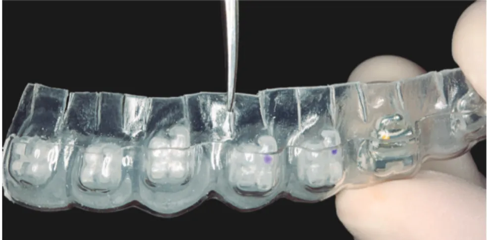
ally confirm tray correct position through the clear tray and light-cure each mesial and distal bracket edges during 10 seconds (Fig 16) or use multiple tip light-curing devices for indirect bonding.
18. Remove the firm Cristal tray with the aid of a smooth tip instrument, first pressing to dislodge it towards the occlusal edge (Fig 17). Use Ma-thieu pliers to pull the Soft tray off the previous-ly slit areas above each bracket, releasing residual retentions (Fig 18), then fully remove the tray. 19. Remove cotton roll isolation and any excess
ad-hesive with proper instruments. Should excess adhesive be noticed around brackets, use specif-ic low-speed burs to remove it. Floss interprox-imal areas to secure they are clean. Orthodontic wires can be inserted immediately (Fig 19).
Figure 16. Fit the transfer tray to teeth without exerting too much pressure. Once confirmed the correct position through the clear tray, light-cure the adhesive.
Figure 17. Remove the Cristal tray, pushing it in the occlusal direction.
Figure 15.A) Acid-etching teeth surfaces after prophylaxis and B) applying ad-hesive. C) Application of a single layer of adhesive to the base of each bracket.
Figure 18. Remove the Soft tray. Use Mathieu pliers to pull off areas above the slits, liberating retention. Follow by completely removing the tray.
Figure 19.A) End of the indirect bonding procedure. B) Orthodontic archwires can be inserted into the slots.
DISCUSSION
The indirect bonding technique should: (1) pro-vide high accuracy in bracket placement and (2) be of simple execution.1 Achieving success with the
de-scribed technique is not complex, provided attention is paid to the recommended details. It allows pre-cise orthodontic appliance installation in only one appointment, and can be used to place any bracket system commercially available.
A critical factor concerning the indirect bonding technique is transferring brackets to teeth with pre-cision and adequate bond strength,15 circumstance
influenced solely by material selection and method of building up a transfer tray. The exclusive use of soft materials can result not only in imprecision in bracket positioning, but also in high incidence of bond failure as a result of poor fitting.16 An example
of soft material is thermoplastic ethylene-vinyl ac-etate copolymer, in the form of a stick (“hot glue”) or in thermoforming sheets.
Faced with a variety of trays made up of different types of material, from silicone-based polymers (clear or opaque) to thermoplastic material,10,17
Cas-tilla et al16 set out to compare in vitro, the accuracy
of five types of transfer tray.8,18,19,20 Addition silicone
trays displayed improved accuracy, but only in the
A
B
C
A
tion, the preference for addition silicone. According to Koga et al,18 the technique using this material is
sensitive, requires agility and efficiency during tray confection and is expensive. The greater complex-ity, material opaccomplex-ity, or even difficulty finding clear silicone within the local market, encourage the use of thermoformed trays.
The proposed technique presents significant modifications when compared to the similar method evaluated by the aforementioned study.16 Some of
the amendments greatly improve accuracy in brack-et placement. The gain in outer tray thickness and boundaries offers improved hardness and stability to the bracket transfer system. At this moment, it is highly recommended that trays be only lightly fitted, without application of additional force to stabilize them, which could cause deviations in ideal bracket positioning. Differences in placement accuracy be-tween right and left sides can arise from non-com-pliance to this recommendation.16
The slits cut on the inner tray represent an-other advantage of this technique. As observed by Wendl et al,15 problems with bonding can arise
from stress caused to the adhesive interface during transfer tray removal. The slits add flexibility to the tray, thus facilitating its removal without trauma. This way, excessive forces over brackets are avoided while the adhesive has not yet reached its peak bond strength. Therefore this implies that methods with excessive retention between tray and brackets can be undesirable, and while reducing tray extension favors its removal, it may lead to undesirable displacement
efficiency is the clear tray. It not only allows visual confirmation of fitting and bracket position at the moment of transference, but also permits the use of light-curable material. The latter provides higher initial bond strength than self-curing materials, an asset at the moment of tray removal and immediate insertion of orthodontic archwires.21 In addition, it
provides enough time for correct tray fitting,21 since
curing only starts upon activation by the operator. Light and self-curable adhesives have been spe-cifically developed for indirect bonding and are com-mercially available. However, clinical experience and experimental studies have shown Transbond XT sys-tem provide excellent results when associated to this technique. The study by Shimizu et al13 supports this
finding by stating that Sondhi Rapid Set and Trans-bond XT Primer systems displayed similar shear Trans-bond strength after the indirect method was employed.
Simplicity, accuracy and reproducibility of this technique lead to its efficiency as an orthodontic bonding method, providing the advantages related to indirect bonding to benefit both professionals and patients involved in this process.
FINAL CONSIDERATIONS
1. Guenthner TA, Larson BE. Indirect bonding: a technique for precision and efficiency. Semin Orthod. 2007;13(1):58-63.
2. Gorelick L, Masunaga GM, Thomas RG, Zachrisson BU. Round table:
bonding. Part 3. J Clin Orthod. 1978;12(12):825-37, 840-2.
3. Hodge TM, Dhopatkar AA, Rock WP, Spary DJ. A randomized clinical
trial comparing the accuracy of direct versus indirect bracket placement. J Orthod. 2004;31(2):132-7.
4. Koo BC, Chung CH, Vanarsdall RL. Comparison of the accuracy of
bracket placement between direct and indirect bonding techniques. Am J Orthod Dentofacial Orthop. 1999;116(3):346-51.
5. Aguirre MJ, King GJ, Waldron JM. Assessment of bracket placement
and bond strength when comparing direct bonding to indirect bonding techniques. Am J Orthod. 1982;82(4):269-76.
6. Sondhi A. Efficient and effective indirect bonding. Am J Orthod
Dentofacial Orthop. 1999;115(4):352-9.
7. Kalange JT, Thomas RG. Indirect bonding: a comprehensive review of
the literature. Semin Orthod. 2007;13:3-10.
8. Sondhi A. Effective and efficient indirect bonding: the Sondhi Method.
Semin Orthod. 2007;13:43-57.
9. Fortini A, Giuntoli F, Franchi L. A simplified indirect bonding technique. J Clin Orthod. 2007;41(11):680-3.
10. White LW. An expedited indirect bonding technique. J Clin Orthod. 2001;35(1):36-41.
11. Ciuffolo F, Epifania E, Duranti G, De Luca V, Raviglia D, Rezza S, et al. Rapid prototyping: a new method of preparing trays for indirect bonding. Am J Orthod Dentofacial Orthop. 2006;129(1):75-7. 12. Ciuffolo F, Tenisci N, Pollutri L. Modified bonding technique for a
standardized and effective indirect bonding procedure. Am J Orthod Dentofacial Orthop. 2012;141(4):504-9.
REFERENCES
13. Shimizu RH, Grando KG, Shimizu IA, Andriguetto AR, Melo ACM, Witters EL. Assessment of shear bond strength of brackets bonded by direct and indirect techniques: An in vitro study. Dental Press J Orthod. 2012;17(4):23e1-5.
14. Nojima LI, Araújo AS, Rio FM, Naldeman P. Resistência adesiva de bráquetes posicionados pelas técnicas de colagem direta e indireta com diferentes sistemas adesivos: estudo in vitro. In: Livro de Resumos da XXXVI Jornada Giulio Massarani de Iniciação Científica, Tecnológica, Artística e Cultural. Rio de Janeiro: Universidade Federal do Rio de Janeiro; 2014. p. 107-8.
15. Wendl B, Droschl H, Muchitsch P. Indirect bonding: a new transfer method. Eur J Orthod. 2008;30(1):100-7.
16. Castilla AE, Crowe JJ, Moses JR, Wang M, Ferracane JL, Covell DA, Jr. Measurement and comparison of bracket transfer accuracy of five indirect bonding techniques. Angle Orthod. 2014;84(4):607-14. 17. Collins J. A precise and predictable laboratory procedure for indirect
bonding. J Clin Orthod. 2000;34(12):702-5.
18. Koga M, Watanabe K, Koga T. Quick Indirect Bonding System (Quick IDBS): an indirect bonding technique using a double-silicone bracket transfer tray. Semin Orthod. 2007;13(1):11-8.
19. Moskowitz EM. Indirect bonding with a thermal cured composite. Semin Orthod. 2007;13(1):69-74.
20. Kalange JT. Prescription-based precision full arch indirect bonding. Semin Orthod. 2007;13(1):19-42.