*e-mail: [email protected]
Surface Modification of Titanium by Plasma Nitriding
Myriam Pereira Kapczinskia, Carlos Gilb, Eder Julio Kinastc, Carlos Alberto dos Santosc*
aFaculdade de Odontologia - ULBRA
Rua Miguel Tostes, 101, 92420-280 Canoas - RS, Brazil bFaculdade de Odontologia - USP
Av. Prof. Lineu Prestes 2227, 05508-900 São Paulo - SP, Brazil cInstituto de Física - UFRGS
C.P. 15051, Campus do Vale, 91501-970 Porto Alegre - RS, Brazil
Received: November 5, 2002; Revised: February 23, 2003
A systematic investigation was undertaken on commercially pure titanium submitted to plasma nitriding. Thirteen different sets of operational parameters (nitriding time, sample temperature and plasma atmosphere) were used. Surface analyses were performed using X-ray diffraction, nuclear reaction and scanning electron microscopy. Wear tests were done with stainless steel Gracey scaler, sonic apparatus and pin-on-disc machine. The obtained results indicate that the tribological performance can be improved for samples treated with the following conditions: nitriding time of 3 h; plasma atmosphere consisting of 80%N2+20%H2 or 20%N2+80%H2; sample temperature dur-ing nitriddur-ing of 600 or 800 °C.
Keywords: plasma nitriding, tribology, titanium, dental implants
1. Introduction
The biocompatibility and good corrosion resistance of commercially pure titanium (c.p. Ti) has motivated its use in medical procedures. The osseointegrated titanium im-plants are reliable alternatives for safety and long time treat-ment, representing advancement in the clinical practice mostly in dental prosthetic1-4. However, occasionally the use of c.p. Ti as implant is problematic as long as it presents low wear resistance5,6.
A crucial issue concerning the removal of the bacterial plaque from the transmucous dental implant cylinders is the possibility of damage by the routine instruments, such as stainless steel Gracey scaler, sonic and ultrasonic appa-ratus7-10. Such an obstacle has been bypassed using mild instrumental, but the results are not satisfactory. An obvi-ous alternative would be the surface modification of the transmucous cylinders to provide better wear resistance. In fact, this has been the subject of several investigations in clinical dentistry4. Among the surface treatment techniques, the most reported are: plasma assisted chemical vapor depo-sition5, conventional ion implantation15-19, plasma source nitrogen ion implantation20, conventional nitriding21,
con-ventional plasma nitriding22,23, intensified plasma ion nitriding24, physical and chemical vapor deposition TiN films25-28, powder immersion reaction assisted coating method29, laser heating30,31 as well as combined tech-niques32,33. Improvement on the mechanical and tribological properties of c.p. Ti and its alloys have been reported11-14.
Aiming the use in clinical procedures, we have started a systematic study on surface treatment of c.p. Ti. Thin film deposition, ion implantation and plasma nitriding are avail-able at our laboratories. We intend to investigate all these processes, but due to recent technological interest we firstly decided to approach the plasma nitriding technique, whose results will be discussed in this paper.
2. Experimental
2.1 Sample preparation
atmosphere.
As previously reported for Ti-6Al-4V alloy, the total pressure has a quite little effect on the surface composition of the nitrided samples36. Therefore, this parameter was al-lowed to vary between 0.5 and 7.5 × 10⁻² Pa. Three differ-ent plasma compositions (nitriding atmosphere) were used (80%N2-20%H2, 60%N2-40%H2, 20%N2-80%H2). The time treatment varied between 3 and 9 h. For each operational condition, two samples were prepared in the same batch.
2.2 Sample characterization
X-ray diffraction (XRD) measurements, in θ-2θ geom-etry (Bragg-Brentano goniometer) were carried out in a Sie-mens diffractometer with monochromated Co Kα radiation (λ1 = 1.78896 Å and λ2 = 1.79285 Å). All the patterns were obtained in the 2θ range between 20° and 110°, with scan step of 0.05° 2θ with a counting time of 2 s. The profile parameters were obtained using Rietveld refinement with the program FullProf37,38. Starting lattice parameters were taken from JCPDS39 files 44-1294 (for α-Ti), 41-1352 (for TiNx) and 38-1420 (for TiN).
Scanning electron microscopy (SEM) micrographs were obtained using Phillips XL 20 microscope equipped with energy-dispersive X-ray spectrometer (EDX). Nitrogen depth profiles were obtained from 14N(p,γ)15O nuclear re-action (RNA) using the 400 kV ion implanter at the Insti-tute of Physics - UFRGS, with protons accelerated to 278 keV. The N concentration (in at.%) is given by
sam cal sam cal S S C C N = 57
where, Ccal and Scal are the count and the stopping power for the calibration (Si3N4), while Csam and Ssam stand for the same parameters for the sample40. Surface roughness measure-ments were made using a Talysurf 5M (Ranck Taylor Hobson) profilometer on all the samples, except for those submitted to pin-on-disc tests. Typical errors are ±10%.
2.3 Tribological experiments
To simulate clinical procedures, wear tests were per-formed with stainless steel Gracey scaler (SS White Duflex G11-G12) and sonic apparatus (Sonicborden 2000 N, Kavo)
manually by a single person, which was well trained to be reproductive.
The generic denomination “pin-on-disc” (POD) test is used for tests where a disc rotate under a pin that can have various formats (ASTM standard41). Although the use of ball instead of pin is increasing, the POD denomination continue to be used. The POD tests were performed in a tribometer (TE79 Plint &Partners) using AISI 52100 balls of 6 mm in diameter. The experiments were done during 600 s in air without lubrication, at ≅ 27 °C and relative hu-midity between 50% and 60%. A normal load of 4 N was applied on a rotating disk with 120 RPM and 3 mm of ra-dius.
3. Results
Firstly, all the samples were submitted to tests with the sonic apparatus. Excepting for samples treated with 600 °C, 80%N2-20%H2, 3 h, 2 × 10⁻² Pa and 800 °C, 20%N
2-80%H2, 3 h, 2 × 10⁻² Pa, all the others, including the c.p. Ti one, have shown severe damages after the test. Besides good wear performance, the sample treated at 600 °C shows colora-tion similar to that of the as-received one. Therefore, con-cerning clinical application this is the best condition. Sev-eral samples were prepared with the same operational pa-rameters, but in different batches to evaluate the process reproducibility. The obtained result is quite favorable. In the following, the treated sample means that one nitrided at 600 °C.
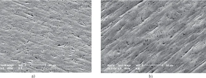
Figure 1. SEM photomicrographs under 450× magnification of (a) c.p. Ti; (b) nitrided sample.
Figure 2. SEM photomicrographs under 450× magnification after test with sonic apparatus in (a) c.p. Ti; (b) nitrided sample.
under 450× SEM magnification (Fig. 2b).The Ra parameter was 0.141 µm in this surface. Patches and abrasions on the photomicrography shown in Fig. 3a indicate that c.p. Ti sample was strongly damaged after test with the Gracey scaler (Ra≅ 0.143 µm), while the nitrided sample (Fig. 3b) appeared smoother after this test (0.098 µm). That is to say, while the as-nitrided sample exhibited Ra ≅ 0.134 µm, the nitrided sample submitted to Gracey scaler test exhibited Ra ≅ 0.098.
Figure 4a shows the photomicrography of c.p. Ti sub-mitted to POD test. The wear track (≅ 0.7 mm) exhibits many grooves typical of abrasive wear. For the nitrided sample, the ball track exhibited a brightness which can be attributed to surface dent. No signal of scratch was observed on this sample (see Fig. 4b). Nevertheless, as illustrated in Fig. 5, a 250× magnification photomicrography exhibited adhered material (see the inset in Fig. 5). Energy-dispersive X-ray spectrometry (EDS) performed on these wear particles showed the presence of iron and oxygen, suggesting they are from the steel ball.
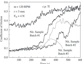
The coefficient of friction (µ) as a function of the slid-ing time for the control and nitrided samples are shown in Fig. 6. The features are typical. After an initial period of about 200 s (400 revolutions) for the control sample and about 300 s for the nitrided sample (batch #1), the coeffi-cient of friction increases from ≅ 0.35 to ≅ 0.50 and from
≅ 0.10 to ≅ 0.50, respectively. Such a behavior can be at-tributed to two effects, which play in a synergetic way. From one side, the consummation of the protective layer leaves the surface more weak against wear. On the other hand, the debris so produced increase the coefficient of friction. Thus, for c.p. Ti, the native oxide layer is supposedly protective against mild wear test, while for the nitrided sample the surface layer can tolerate more severe tests. In this sense, it is interesting to point out other differences among the
re-Figure 5. SEM photomicrographs under 70× magnification after
POD test in a nitrided sample. The circle in the inset shows where EDS was performed.
Figure 4. SEM photomicrographs under 70× magnification after POD test in (a) c.p. Ti; (b) nitrided sample.
Figure 6. Coefficient of friction as a function of the sliding time
sults obtained for these samples. Firstly, the initial value of
µ for the nitrided sample is about 3 times smaller than for c.p. Ti. Second, the features exhibited by the nitrided sam-ple suggest that the wear is of the abrasive type, as this pat-tern is typical of wear particles at the sliding interface42,43. To properly discuss such a process it is interesting to have some insight on the physicochemical state of the sliding surfaces. As discussed below, we approached this point per-forming XRD and NRA measurements.
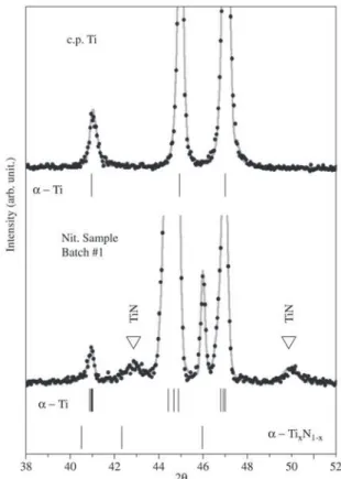
Figure 7 displays significant parts of the XRD patterns for the control and nitrided sample batch #1 (all batches gave quite similar patterns). The patterns were fitted by means of a Rietveld procedure, whose results are summa-rized in Table 1. The main contribution in each one of the spectra is due to α-Ti, whereas the minor ones are due to different titanium nitrides and Ti(N) solid solutions. The nitrided sample exhibited cubic phase TiN in addition to hexagonal phases α-Ti and α-TiNx44. The α-Ti phase is present with three different cell-parameter values, which we named α-Ti(1), α-Ti(2) and α-Ti(3). These phases can be attributed to different N-saturated á-phases or to sub-stoichiometric phases similar to α-TiN0.2518, α-TiN
0.26 (JCPDS file 44-1095) or α-TiN0.30 (JCPDS file 41-1352).
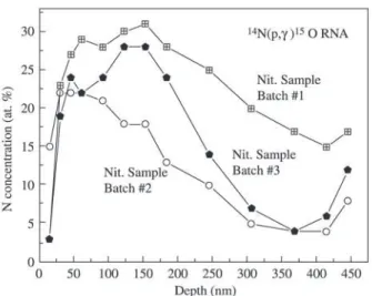
To better understand such a result we have performed NRA to access the near-surface nitrogen concentration. As shown in Fig. 8, between 50 nm and 250 nm the N concen-tration is higher than 25 at.%. Between 250 nm and 400 nm the concentration is between 25 at.% and 15 at.%. The near-surface layer could provides precipitation of δ-TiN, while the deeper one would be consistent with ε-Ti2N precipita-tion19,42,45. The lack of reflections attributed to ε-Ti
2N in
Figure 7. Rietveld analysis (solid line) of XRD patterns
(experi-mental points) for c.p. Ti and nitrided sample. The a-Ti, a-TiNx reflections are indicated by vertical bars. Those for TiN and indi-cated by triangles.
Table 1. Cell-unit parameters and agreement factor RB for sample nitrided at different batches. Numbers in brackets designate ±1 s on the
last decimal given.
RB = 100
Σ
| Ik (obs) - Ik (calc) |/
Σ
Ik (obs)Phase a (Å) RB (%) a (Å) RB (%) a (Å) RB (%)
c (Å) c (Å) c (Å)
α-Ti (1) 2.959(8) 1.16 2.958(5) 1.31 2.960(3) 1.34
4.731(7) 4.728(6) 4.726(5)
α-Ti (2) 2.950(7) 2.46 2.952(0) 1.74 2.951(8) 1.98
4.687(8) 4.688(5) 4.687(9)
α-Ti (3) 2.953(3) 1.04 2.954(5) 1.06 2.954(6) 0.928
4.709(1) 4.722(3) 4.708(0)
TiN 4.24(4) 4.06 4.24(7) 5.25 4.24(2) 3.67
4.24(4) 4.24(7) 4.24(2)
TiNx 2.984(0) 3.30 2.982(7) 1.61 2.983(9) 2.62
4.95(7) 4.97(9) 4.96(0)
Batch 1 Batch 2 Batch 3
Fig. 7 is probably because its layer thickness is below the detection limit for Co Kα radiation.
4. Discussion
The test with the sonic apparatus produced on c.p. Ti an effect similar to those observed after tests with Implacare scaler and Cavitron7,10. As shown in Fig. 2a, roughening of the surface and material loss are evident. In this sense, a meaningful difference is observed when compared to the results obtained for the nitrided sample, which does not show any apparent surface damage, even at microscopic level (Fig. 2b). Taking into account data from Brookshire et al.46, the present tests are comparable to several years of implant maintenance. The different α-Ti phases detected with XRD analysis can be attributed to nitrogen, as well as to oxygen present in interstitial sites. In fact, the presence of oxide in this material is well known and has been reported by Brånemark et al.2.
Now, let us discuss the correlation between near-sur-face composition and tribological behavior. During the first step of the sliding experiment (up to ≅ 300 s for the nitrided sample), surface oxidation is promoted by the increasing of the temperature in the contact zone. As α-TiNδ reacts strongly with oxygen19, a oxynitride layer quickly growth with the sliding time, resulting in a low friction coefficient. When this layer reaches a critical thickness it will peel off, producing debris and increasing the friction coefficient.
5. Summary and Conclusion
Near-surface composition and tribological behavior of plasma nitrided c.p. Ti have been investigated using X-ray diffraction, nuclear reaction analysis, scanning electron microscopy, profilometry, wear tests with stainless steel Figure 8. Near-surface nitrogen concentration as a function of the
depth for nitrided sample. The solid line is a guide to the eyes.
In conclusion, it is demonstrated that plasma nitriding is useful to improve dental implant tribological behavior.
Acknowledgments
This work was supported in part by the Brazilian agen-cies CAPES, CNPq(PRONEX) and FAPERGS.
References
1. Adell, R.; Eriksson, B.; Lekholh, U.; Brånemark, P.; Jemt, T. Int J Oral & Maxillofac Implants, v. 5, n. 4, p. 347-359, 1990.
2. Brånemark, P.; Zarb, G.; Albrektsson, T. Prótesis tejido-integradas. La osseointegración en la odontologia clínica. Quintessenz Verlags-GmbH, Berlin, Germany, p. 350, 1987.
3. Jemt, T.; Lekholm, U.; Adell, R. Int J Oral & Maxillofac Implants, v. 4, n. 3, p. 211-217, 1989.
4. Mezger, P.R.; Creugers, N.H.J. J Dent, v. 20, n. 6, p. 342-344, 1992.
5. Rie, K.; Stucky, T.; Silva, R.A.; Leitão, E.; Bordji, K.; Jouzeau, J.Y.; Mainard, D. Surf Coat Technol, v. 74-75, n. 1-3, p. 973-980, 1995.
6. Wang, K. Mat Science & Eng, A 213, p. 134-137, 1996. 7. Matarasso, S.; Quaremba, G.; Coraggio, F.; Vaia, E.; Cafiero, C.; Lang, N.P. Clin Oral Impl Res, v. 7, n. 1, p. 64-72, 1996.
8. McCollum, J.; O’Neal, R.B.; Brennan, W.A; Van Dyke, T.E.; Horner, J. Periodontol 2000, v. 63, n. 10, p. 802-805, 1992.
9. Orton, G.; Steele, D.; Wolinsky, L. Int J Oral Maxillofac Implants, v. 4, p. 305-310, 1989.
10. Rapley, J.W; Swan R.H.; Hallmon W.W.; Mills M.P. Int J Oral Maxillofac Implants, v. 5, n. 1, p. 47-52, 1990. 11. Efeoglu, I.; Arnell, R.D.; Tinston, S.F. Surf Coat Technol,
v. 57, n. 1, p. 61-69, 1993.
12. Johansson, C.; Lausmaa, J.; Röstlund, T.; Thomsen, P. J Mater Sc Mater Med, v. 4, n. 2, p. 132-141, 1993. 13. Takadoum, J.; Bennani, H.H. Surf Coat Technol, v. 96,
n. 2-3, p. 272-282, 1997.
14. Wilson, S.; Alpas, A.T. Surf Coat Technol, v. 94-95, n. 1-3, p. 53-59, Oct. 1997.
16. Dong, H.; Shi, W.; Bell, T. Wear, v. 225-229, p. 146-153, 1999.
17. Itoh, Y.; Itoh, A.; Azuma, H.; Hioki T. Surf Coat Technol, v. 111, p. 172-176, 1999.
18. Guemmaz, M.; Mosser, A.; Grob, J.J. Appl Phys, A 64, p. 407-415, 1997.
19. Pons, F.; Pivin, J.C.; Farges, G. J Mater Res, v. 2, p. 580-587, 1987.
20. Qiu, X.; Conrad, J.R.; Dodd, R.A.; Worzala, F.J. Metall Trans, v. 21, p. 1663-1667, 1990.
21. Venugopalan, R.; George, M.A.; Weimer, J.J.; Lucas, L.C. Biomaterials, v. 20, p. 1709-1716, 1990.
22. Wierzchon, T.; Fleszar, A. Surf Coat Technol, v. 96, p. 205-209, 1997.
23. Salehi, M.; Bell, T.; Morton, P.H. J Phys D: Appl Phys, v. 25, p. 889-895, 1992.
24. Meletis, E.I.; Surf Coat Technol, v. 149, p. 95-113, 2002. 25. Shima, M.; Okado, J.; McColl, I.R.; Waterhouse, R.B.; Hasegawa, T.; Kasaya, M. Wear, v 225-229, p. 38-45, 1999.
26. Wu, P.Q.; Drees, D.; Stals, L.; Celis, J.P. Surf Coat Technol, v. 113, p. 251-258, 1999.
27. Vitchev, R.G.; Blanpain, B.; Celis, J.P. Wear, v. 231, p. 220-227, 1999.
28. Vancoille, E.; Banpain, B.; Xingpu, Y.; Celis, J.P.; Roos, J.R. J Mater Res, v. 9, p. 992-998, 1994.
29. Shenhar, A.; Gotman, I.; Radin, S.; Ducheyne, P.; Gutmanas, E.Y. Surf Coat Technol, v. 126, p. 210-218, 2000.
30. Yilbas, B.S.; Shuja, S.Z. Surf Eng, v. 16, p. 519-523, 2000.
31. L’Enfant, H.; Laurens, P.; Sainte Catherine, M.C.; Dubois, T.; Amouroux, J. Surf Coat Technol, v. 96, p. 169-175, 1997.
32. Labudovic, M.; Kovacevic, R.; Kmecko, I.; Chan, T.I.;
Blecic, D.; Blecic, Z. Metall Mater Trans, A 30, p. 1597-1603, 1999.
33. Rodrigo, M.T.; Jiménez, C.; Vázquez, L.; Alonso, F.; Fernández, M.; Martínez-Duart, J.M. J Mater Res, 1998; v. 13, p. 2117-2122, 1998.
34. Santos, C.A. Ion nitriding, Cooperativa Cultural da UFRN, Natal, Brazil, 1989 (in Portuguese).
35. Hudis, M.J. Appl. Phys, v. 44, p. 1489-1492, 1973. 36. Silva, S.L.R.; Kerber, L.O.; Amaral, L.; Santos, C.A.
Surf Coat Technol, v. 116-119, p. 342-346, 1999. 37. Rodriguez-Carvajal, J. Physica B, v. 192, p. 55-57, 1993. 38. Kinast, E.J. Structural refinement with the Rietveld method: implementation and essays with the program Fullprof, MSc dissertation (in Portuguese), Instituto de Física - UFRGS, Porto Alegre, Brazil, 2000.
39. Joint Committee on Powder Diffraction Standards. Pub-lished by International Centre for Diffraction Data, Swarthmore, Pennsylvania, USA.
40. Feldman, L.C.; Picraux, S.T. Selected low energy nu-clear reaction data. In: Mayer, M., Rimini, E., editors. Ion beam handbook for material analysis. London: Aca-demic Press, p. 109-309, 1997.
41. American Society for Testing and Materials, Standard test method for wear testing with a pin-on-disk appa-ratus, G 99, Philadelphia, USA, 1990.
42. Muraleedharan, T.M.; Meletis, E.I. Thin Solid Films, v. 221, p.104-113, 1992.
43. Hwang, D.H.; Kim, D.E.; Lee, S.J. Wear, v. 225-229, p. 427-439, 1999.
44. Beck, U.; Reiners, G.; Kopacz, U.; Jehn, H.A. Surf Coat Technol, v. 60, p. 389-395, 1993.
45. Badini, C.; Gianoglio, C.; Bacci, T.; Tesi, B. J. Less-Common Metals, v. 143, p.129-141, 1988.