*e-mail: [email protected]
Plasma Sintering of Unalloyed Iron: A Study of Surface Porosity
Jorge Magner Lourençoa,b, Ana Maria Maliskab*, Aloísio Nelmo Kleinb,
Joel Louis Rene Muzartb
aCentro Federal de Educação Tecnológica,
CEFET-RN, GETIN, Natal - RN, Brazil
bLABMAT, Departamento de Engenharia Mecânica,
Universidade Federal de Santa Catarina, 88040-900 Florianópolis - SC, Brazil
Received: August 01, 2003; Revised: November 15, 2003
Samples of unalloyed iron powder were compacted and sintered in an abnormal glow discharge, generated in a gas mixture of 80% Ar + 20% H2 by using a pulsed power source. The samples were placed on a holder, acting as the discharge cathode, and were heated by the bombardment of ions, strongly accelerated in the cathode sheath. Sintering was performed at temperatures of 1173, 1273 and 1373 K for 30 min, varying the voltage applied to the cathode from 400 to 700 V and pressure ranging from 470 to 2650 Pa. It is shown that the kinetic energy of ions striking the sample surface increased approximately three times, when the voltage changed from 400 to 700 V, with a corre-sponding reduction of surface porosity. The surface sealing is related to the ion bombardment, which produced a high mobility of surface atoms and consequent enhanced diffusion as well as sputtering and condensation on the concave surface, resulting in an activation of surface sintering.
Keywords:Powder metallurgy, Plasma sintering, Surface porosity
1. Introduction
Glow discharge processes, as plasma assisted chemical vapor deposition (PACVD), plasma assisted physical vapor deposition (PAPVD), etching, nitriding or nitrocarburizing and surface cleaning are exhaustively used in industry1-12.
In these techniques, the reactive species generated in the plasma produce an activated processing and the ion bom-bardment of the parts or the target is used for heating or sputtering respectively. Sintering of ceramics using micro-wave cavities, hollow cathode devices and micromicro-wave or RF-inductively coupled discharges have been investigated for plasma sintering13-16. The technique was applied to sinter
ceramics as alumina or MgO and MgO-TiC. In those papers it has been reported that ceramics could be sintered to high density at high sintering rates. Heat transfer mechanism and the surface cleaning of the particles in the plasma envi-ronment are suggested to be responsible for the enhanced sintering. High-density samples at high rate sintering may also be obtained using the PAS (plasma activated sintering) or SPS (spark plasma sintering) process17-22. The pulsed
voltage applied to the sample removes impurities from
par-ticle surfaces and activates sintering. Following the clean-ing of the particle surfaces, a direct current associated with a pulsed one flows among the powders and the contact resistance between the particles generates Joule heat23. This
localized heating accelerates the formation of necks, lead-ing to the activation of sinterlead-ing. The application of plasma technology on powder metallurgy processing is mainly used for surface treatment24-27, cleaning28 or sintering29-33. In these
papers, an abnormal glow discharge of a gas mixture con-stituted of argon, hydrogen, nitrogen and methane was used. The abnormal glow discharge is characterized by the whole covering of the cathode by the glow region2, supplying a
uniform treatment. A negatively biased voltage was applied to the cathode, generating an electric field in the cathode sheath, where ions are strongly accelerated. Collisions be-tween ions and atoms or molecules of the gas discharge in the cathode sheath resulted in a flow of fast neutrals toward the cathode2. When the sample is placed on the cathode,
pump, pressure sensor and electrodes, electrically insulated, were connected to the steel plates. Prior to sintering, the system was pumped down by a two-stage mechanical pump until a residual pressure of less than 1.3 Pa was reached. The gas mixture consisting of 80% argon (99.999% pure) and 20% hydrogen (99.998% pure) was adjusted using two Datametrics mass flow controllers whose full-scale value was 8.3 × 10⁻⁶ m3/s-1 (500 sccm) and the total gas flow was
set to 4 × 10⁻⁶ m3/s-1 (240 sccm). The pressure in the vacuum
chamber was adjusted and measured with accuracy better than 2% by a manual valve and measured using an Edward capacitance manometer of 13300 Pa (100 Torr) full-scale.
Iron powder DC177 from Hoeganaes was sieved in or-der to obtain particle size ranging from 43 to 63 µm. Then
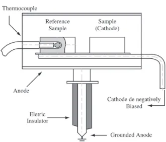
the powder was mixed with 0.6% wt of zinc stearate and compacted to a pressure of 500 MPa using a double action press with moving die body. The samples, 9.5 mm in diam-eter and 6 mm high, were placed on a steel AISI 1020 sup-port working as the cathode of the discharge. The experi-mental scheme is illustrated in Fig. 2. The cathode was negatively biased, using a power source of 5 kW, which generated a square waveform pulse voltage varying from 400 to 700 V. The sample temperature was adjusted by vary-ing the time switched on (ton) of the pulse, which could be varied from 10 to 240 µs and the total on/off time was 250 µs.
Symmetrically placed to the sample, a cylinder of sintered
a conventional furnace in hydrogen gas at atmospheric pres-sure, following the same processing cycle.
Micrographs of the surface of the sintered samples were obtained by using a scanning electron microscope. The BSE (back-scattered electron) pictures for the image analy-ses were taken using a 200 × magnification. The porosity was determined by image analyses using a rectangle of 480 × 360 mm of the binarised image. The results are an average of measurements carried out in six different posi-tions on the lateral part of the sample.
3. Results and Discussion
3.1. Comparative results of conventional and plasma sintering
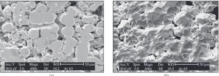
Micrographs of the lateral surface of green (a) and sintered at 1373 K (b) samples are presented in Figs. 3, 4 and 5. The images were carried out at the same region in order to identify the evolution of the sealing after sintering. The plasma sintering was performed in two conditions, whose parameters are presented in Table 1.
Figure 1. Experimental apparatus.
Figure 5. a) Micrographs of samples surface in the green state; b) plasma-sintered in condition 2 (700 V, ton = 140 µs and 470 Pa).
(a) (b)
Figure 4. a) Micrographs of samples surface in the green state; b) plasma-sintered in condition 1 (400 V, ton = 80 µs and 2650 Pa). (b)
(a)
Figure 3. a) Micrographs of samples surface in the green state; b) sintered in a conventional furnace.
ion bombardment of the sample surface, as compared to the condition 1. Such an effect is associated with the enhanced condensation of atoms resulting from sputtering and the increased surface diffusion of atoms resulting from the high-energy ion bombardment of the sample surface. As discussed by Thümmler and Oberacker34, besides the volume and grain
boundary diffusion, there are two mechanisms of material transport during sintering: evaporation and condensation of atoms and surface diffusion. The condensation of atoms occurs preferentially on the concave surface, the pore, where vapour pressure is lower. For the same reason, surface diffu-sion takes place from the convex to the concave surface, where the particle contact initiates. Then, by diffusion of theses atoms, the particle contacts grow. On the surface of the sample, sintering may result mainly from the condensa-tion and surface diffusion of atoms. By using plasma tech-nique, ions arriving at the interface between the glow re-gion and the cathode sheath are strongly accelerated to-wards the cathode. At usual sintering pressures (between 300 and 4000 Pa) the flow of ions of high energy, typically 10 to 60 eV 35, impacting the cathode causes three main
effects: heating, sputtering of atoms from the cathode and kinetic energy transfer to the atoms of the surface. When the pressure was maintained at 470 Pa, the mean free path of ions, between collisions with atoms, is higher than that occurring when the pressure was fixed at 2650 Pa. Thus, it could be expected that the kinetic energy of ions striking the sample surface, which is an increasing function of the electric field in the cathode sheath and inversely propor-tional to the gas pressure, is significantly higher in condi-tion 2 as compared to condicondi-tion 1. As a consequence of sputtering, a high concentration of iron atoms occurred in the gas phase accompanied by an enhanced condensation. In addition, the higher energy of ions striking the sample surface resulted in an activated diffusion, contributing to the porosity sealing. In order to quantify the activated sur-face sintering observed by using condition 2, results of surface porosity, measured for three sintering temperatures, are presented in Fig. 6. As expected, in all sintering condi-tions, as the temperature increased, there was an approxi-mately linear reduction of the surface porosity. For
conven-tional furnace and plasma sintering in condition 1, consid-ering the dispersion of the measurements, the same poros-ity was obtained, ranging from approximately 23% at 1173 K to 17% at 1373 K. On the other hand, when sintering was performed by plasma in condition 2, the porosity ranged from 10 to 4% for the same temperature variation.
3.2. Variation of surface porosity as a function of average energy of ion bombardment
The average kinetic energy of ions striking the sample surface was varied by changing the voltage applied to the cathode. The experiments were performed for a ton fixed at 80 and 140 µs and the temperature was maintained at
1373 K. The current of the discharge and consequently the temperature is an increasing function of the voltage ap-plied to the cathode as well as of the gas pressure. Thus, as ton was maintained constant, in order to maintain the tem-perature at 1373 K, by increasing the voltage applied to the cathode, the pressure of the discharge had to be lowered as shown in Table 2.
The energy of ions (E) is proportional to the voltage fall (V) in the cathode sheath, which is nearly the voltage ap-plied to the cathode36 and an inverse function of the number
of collisions (N):
(1)
The number of collisions of ions with atoms or mol-ecules is proportional to the thickness d of the cathode sheath and inversely proportional to the mean free path of the ions. On the other hand, the mean free path is inversely proportional to the number of atoms or molecules in the gas phase, which is itself proportional to the pressure, at constant temperature. Then,
N = C2 (p.d) (2)
It follows that,
(3)
where C1, C2and C3 are constant values.
Results published by Guntherschulze in 1930 and pre-sented by von Engel37, show the variation of p.d as a
func-tion of the voltage applied to the discharge for argon and hydrogen gases. Considering the gas mixture of 80% Ar + 20% H2, the values of p.d were calculated and are represented in Fig. 7 by squares. The experimental values of the pressure for different voltages, for a ton = 140 µs, used
to sinter the samples at 1373 K are also plotted at Fig. 7 and identified by crosses. The product p.d corresponding to each sintering pressure was then determined, and by using equation (3) the factor V (p.d)-1 proportional to the energy
of ions, was calculated. The same procedure was used, con-sidering a curve similar to that presented in Fig. 7, to calcu-late the factor V.(p.d)-1 for t
on = 80 µs. The results are
pre-sented in Table 3. Clearly, the energy of ions bombarding the surface of the sample increased as a function of the increasing voltage, being around 3 times higher at 700 than at 400 V. Considering that the average ion energy is, typi-cally, lower than 100 eV 35, the ion implantation is
negligi-ble2; thus, interaction occurs mainly with the surface
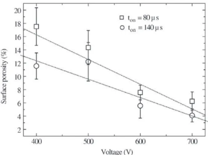
at-oms. As a consequence, the increase of energy of the ions bombarding the sample surface resulted in an increase of kinetic energy that was transferred to the atoms on the sur-face. Such an effect, takes place not only to evaporated or sputtered atoms followed by the deposition, but also to atoms of the surface lattice. Therefore, an enhanced mobil-ity and surface diffusion of the iron atoms occurred, result-ing in an efficient porosity sealresult-ing, as it shown in Fig. 8.
3.3. Variation of surface porosity as a function of ton of the pulse of the power source
Results of surface porosity of samples sintered at 1373 K as a function of ton, are presented in Fig. 9. The sintering experiments were performed for the power source voltage fixed at 400 and 700 V. In order to maintain the temperature at 1373 K, the pressure was adjusted as shown
in Table 4. The energy of ions striking the sample surface in each condition was calculated using the same procedure used previously and the results are also presented in Ta-ble 4. From the variation of p.d as a function of voltage, presented in Fig. 7, the evaluation of the number
propor-Table 2. Gas pressure of the glow discharge for different voltage applied to the cathode, for ton fixed at 80 and 140 µs. The sample temperature was maintained at 1373 K.
ton (µs) Voltage (V) Pressure (Pa)
400 2650
80 500 1300
600 780
700 580
400 1185
140 500 825
600 630
700 470
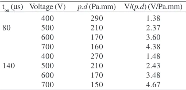
Table 3. Variation of the product p.d and V(p.d)-1 as a function of
voltage. The sample temperature was maintained at 1373 K.
ton (µs) Voltage (V) p.d (Pa.mm) V/(p.d) (V/Pa.mm)
400 290 1.38
80 500 210 2.37
600 170 3.60
700 160 4.38
400 270 1.48
140 500 210 2.43
600 170 3.48
700 150 4.67
tional to ion kinetic energy was calculated with an accu-racy of 10%. Thus, it can be considered that in all experi-ments performed at a fixed voltage, the energy of ions im-pinging the sample surface was the same. As expected, the porosity measured for a voltage of 700 V was significantly lower than the one obtained at 400 V, as a consequence of the higher kinetic energy of ions. On the other hand, the decrease of surface porosity measured, either at voltages of 400 and 700 V, for an increasing function of ton, is simply attributed to the higher effective time of ion bombardment of the sample surface. Such a result is related to the higher time of activated surface sintering mechanisms, which is an additional evidence of the influence of ion bombardment on the surface porosity sealing.
5. Conclusions
An abnormal glow discharge has been shown to be an efficient approach to sinter metallic components. When the sample was placed on a holder, which worked as the cath-ode of the discharge, the surface porosity was strongly de-pendent on the kinetic energy of the ions striking the
sam-Figure 8. Variation of surface porosity of samples sintered at 1373
K as a function of the discharge voltage. Figure 9.function of t Variation of surface porosity of sintered samples as a
on.
Table 4. Variation of pressure, product p.d and V(p.d)-1 as a function of t
on for the voltage of 400 and 700 V applied to the cathode. The sample
temperature was maintained at 1373 k.
Voltage (V) ton (µs) Pressure (Pa) p.d (Pa.mm) V/(p.d) (V /Pa.mm)
80 2640 290 1.38
400 110 1610 280 1.43
140 1185 270 1.48
80 580 160 4.38
700 110 510 160 4.38
140 470 150 4.66
ple. The higher the kinetic energy of ions bombarding the sample surface, the lower was the measured surface poros-ity. In addition, increasing the effective time of ion bom-bardment of the sample surface, a reduction of porosity was observed, confirming the dependence between surface po-rosity and interaction ion-surface. Such an effect is attrib-uted to surface sintering mechanisms, as enhanced conden-sation of atoms resulting from sputtering and the activated surface diffusion of iron atoms resulting from the ion bom-bardment of the sample surface.
Acknowledgments
This work was performed using funds from FINEP/MCT (PRONEX) and CNPq (PADCT) research grant.
References
1. Rhode, S.L.; Münz, W.D. Advanced Surface Coatings: A Handbook of Surface Engineering, Blake & Son Ltd, p. 127, 1991.
York, p. 178, 1980.
3. Butz-Jorgensen, C.V.; Kringhoj, P.; Nielsen, J.F.; Bottiger, J. Surf. Coat. Technol., v. 135, p. 299, 2001.
4. Window, B. Surf. Coat. Technol., v. 81, p. 92, 1996. 5. Fontana, L.C.; Muzart, J.L.R. Surf. Coat. Technol., v.
114, p. 7, 1999.
6. Hombecck, F., Bell, T., Surface Engineering, v. 7, n. 1, p. 45, 1991.
7. Rembges, W., Metal Powder Report, p. 765, 1988. 8. Bell, T.; Sun, Y.; Suhadi, A. Vacuum, v. 59, p. 14, 2000. 9. Musil, J.; Vlèek, J.; Rù•ièka, M. Vacuum, v. 59, p. 940,
2000.
10. Belkind, A.; Li, H.; Clow, H.; Jansen, F. Surf. Coat. Technol., v. 76-77, p. 738, 1995.
11. Petasch, W.; Kegel, B.; Schmid, H.; Lendenmann, K; Keller, H.U. Surf. Coat. Technol., v. 97, p. 176, 1997. 12. Mozetiè, M. Vacuum, v. 61, p. 367, 2001.
13. Johnson, D.L.; Sanderson, W.B.; Knowlton, J.M.; Kemer, E.L.; Chen, M.Y. Science of Sintering, v. 20, n. 2/3, p. 109, 1988.
14. Page, R.A.; Spooner, S.; Sanderson, W.B.; Johnson, D.L. J. Am. Ceram. Soc., v. 71, n. 12, p. 1125, 1988. 15. Bengisu, M.; Inal, O.T. J. Mater. Sci., v. 29, p. 5475,
1994.
16. Su, H.; Johnson, D.L. J. Am. Ceram. Soc., v. 79, n. 12, p. 3199, 1996.
17. Groza, J.R.; Risbud, S.H.; Yamazaki, K. J. Mater. Res., v. 7, n. 10, p. 2643, 1992.
18. Mishra, R.S.; Schneider, J.A.; Shackelford, J.F.; Mukherjee, A. K. NanoStructured Materials, v. 5, n. 5, p. 525, 1995.
19. Li, W.; Gao, L. J. Euro. Ceramic Soc., v. 20, p. 2441, 2000.
20. Ye, L.L.; Liu, Z.G.; Raviprasad, K.; Quan, M.X.; Umemoto, M.; Hu, Z.K. Materials Science and Engi-neering, v. A241, p. 290, 1998.
21. Takeuchi, T.; Bétourné, E.; Tabuchi, M.; Kageyama, H.; Kobayashi, Y.; Coats, A.; Morrison, F.; Sinclair, D.C.;
West, A.R. J. Mater. Sci., v. 34, p. 917, 1999.
22. Murakami, T.; Komatsu, M.; Kitahara, A.; Kawahara, M.; Takahashi, Y.; Ono, Y. Intermetallics, v. 7, p. 731, 1999.
23. Matsumoto, A.; Katoh, K.; Andoh, K. Corrosion Engi-neering, v. 44, p. 751, 1995.
24. Tosic, M.M.; Tersic, I.; Gligorijevic, R. Vacuum, v. 40, n. 1, p. 131, 1990.
25. Bocchini, G.F. Int. J. Powder Metall., v. 22, n. 3, p. 185, 1986.
26. Maliska, A.M.; Klein, A.N.; Souza, A.R. Surf. Coat. Technol., v. 70, p. 175, 1995.
27. Maliska, A.M.; Oliveira, A.M.; Klein, A.N.; Muzart, J.L.R. Surf. Coat. Technol., v. 141, p. 128, 2001. 28. Santos, M.A.; Silva, H.R.T.; Muzart, J.L.R.; Maliska,
A.M. Third Inter. Latin American Conf. on Powder Technol, Florianópolis, p. 561, Nov., 26-28, 2001. 29. Muzart, J.L.R.; Batista, V.J.; Franco, C.V.; Klein, A.N.
Advances in Powder Metallurgy & Particulate Materi-als, v. 3, p. 77, 1997.
30. Batista, V.J.; Binder, R.; Klein, A.N.; Muzart, J.L.R. Int. J. Powder Metall, v. 34, n. 8,p. 55, 1998.
31. Batista, V.J.; Mafra, M.; Muzart, J.L.R.; Klein, A.N.; Back, N. Mater. Sci. Forum, v. 299, n. 3, p. 249, 1999. 32. Brunatto, S.F.; Kühn, I.; Klein, A.N.; Muzart, J.L.R. Third
Inter. Latin American Conf. on Powder Technol, Florianópolis, p. 488, Nov., 26-28, 2001.
33. Brunatto, S.F.; Kühn, I.; Klein, A.N.; Muzart, J.L.R. Mat. Sci. Eng. A, v. 343, n. 1-2, p. 163, 2002.
34. Thümmler, F.; Oberacker, R. Introduction to Powder Metallurgy, The Institute of Materials, London, p. 184, 1993.
35. Mason, R.S.; Pichilingi, M. J. Phys. D: Appl. Phys, v. 27, p. 2363, 1994.
36. Butz-Jørgensen, C.V.; Bøttiger, J.; Kringhøj, P. Surf. Coat. Technol., v. 137, p. 104, 2001.