ABSTRACT: The growing countries that have carried out the development of CubeSat missions for academic purposes do not offer aerospace engineering programs at their universities. This causes dificulties for traditional engineers upon the formal use of different standards and frameworks for aerospace development, such as the European Cooperation for Space Standardization and Space Mission Analysis and Design . One way in which traditional software engineers can easily understand the structure of an aerospace framework, in order to apply it on the development of CubeSat mission software parts, is comparing its most important elements in relation to the elements suggested by a more familiar method. In this paper, we present a hybrid framework between the ECSS-E-ST-40C standard and the Rational Uniied Process, which can be used by traditional software engineers as a guide model for the development of software elements in academic nanosatellite missions. The model integrates the processes and documentation suggested by the ECSS-E-ST-40C with the disciplines, worklows and artifacts suggested in Rational Uniied Process. This simpliies the structure of ECSS-E-ST-40C and allows traditional software engineers to easily understand its work elements. The paper describes as study case the implementation of the hybrid model in the analysis and design of ground monitoring and control software for the Libertad-2 satellite mission, which is currently being developed by the Universidad Sergio Arboleda in Colombia.
KEYWORDS: CubeSat, European Cooperation for Space Standardization, Rational Uniied Process, Monitoring, Graphical User Interface, 3D.
Design of a Nanosatellite Ground Monitoring
and Control Software – a Case Study
Freddy Alexander Díaz González1, Pablo Roberto Pinzón Cabrera1, Claudio Marcel Hernández Calderón1
INTRODUCTION
he development of academic satellites projects, mostly based on the CubeSat standard, has become the best alternative for those countries who want to start research and development on aerospace themes (Woellert et al. 2011). he feasibility of using Commercial of-the-shelf (COTS) components for the development of satellite modules and the possibility to be secondary cargo on the rocket launchers, through modules as the Poli-Picosatellite Orbital Deployer (P-POD), allow the launch of small satellites (1 – 10 kg) (Buchen 2014) with shoestring budgets (Woellert et al. 2011); however, due to the lack of experience that growing countries have in research and development of satellite technology, their universities do not have yet speciic programs to train aerospace engineers; for this reason, academic satellite missions such as CubeSatshould be developed with local engineers, trained in conventional development of hardware (HW) and sotware (SW), with assistance of aerospace experts trained in the United States (US) and Europe (Nader et al. 2014). he only country in Latin America that provides aerospace engineering programs is Brazil, at the Universidade
Federal de Minas Gerais, Universidade de Brasília and
the Universidade do Vale do Paraíba(Armellini et al. 2012). he nearest approaches to aerospace programs in Latin America are aeronautical engineering degrees offered in Ecuador, Argentina, Peru, among others. Currently in Colombia, satellite missions aim to generate experience in the development of aerospace technology in medium term, through the training of professionals with the concept of learning by doing (Villamil and Mayorga 2013), and the creation of university programs focused on the aerospace theme; however, as this process
1.Universidad Sergio Arboleda – Escuela de Ciencias Exactas e Ingeniería – Bogotá – Colombia.
Author for correspondence: Freddy Alexander Díaz González | Universidad Sergio Arboleda – Escuela de Ciencias Exactas e Ingeniería | Calle 74 14-14 | Zip Code: 110221201 – Bogotá – Colombia | Email: [email protected]
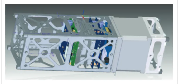
Figure 1. Partial view of the Libertad-2 satellite structural design. matures, local engineers are responsible for the development
of the i rst satellite missions.
Due to the peculiarity that exists in the operational context of a satellite system, it is necessary the use of development methodologies that address the characteristics of aerospace type, to guide the dif erent stages of analysis, design, implementation, validation and operation of each subsystem of the mission. h e most commonly used are those proposed by the National Aeronautics and Space Administration (NASA), called Space Mission Analysis and Design (SMAD) (Webster and Corcoran 2007; Puschell 2011), and standards of the European Cooperation for Space Standardization (ECSS), proposed by the European Space Agency (ESA) (Raphael et al. 2014). Nevertheless, these models are oversized for small academic missions as CubeSat ones. One way to provide local engineers with the appropriation of aerospace concepts suggested by these models is by identifying relationships between common elements of conventional development methodologies known by local engineers and aerospace development models, such as milestones, steps, artifacts, suggested activities and life cycles.
Given that SMAD and ECSS have a similar structure, a comparative analysis of the life cycle phases, milestones, artifacts and activities dei ned, among ECSS and the Rational Unii ed Process (RUP), is presented in this study (Ramos et al. 2010). RUP is one of the best known SW development methodologies and it is commonly used by local engineers. h e proposed analysis results in a hybrid framework, whereby local engineers can appropriate and guide the development process of the dif erent academic satellite SW elements. To validate the proposed hybrid model, the design of the ground monitoring and control SW for Libertad-2 nanosatellite – as the main component of the Mission Control Center (MCC) – is taken as a study case.
The paper is presented in the following order: first, a description of Libertad-2 satellite mission; the importance of developing SW as a fundamental element of a nanosatellital system is explained; the presentation of SMAD and ECSS standards is done; ECSS-E-ST-40C standard is specii cally described; and a presentation of commercial SW development methodologies is made. Then, the life cycles of RUP and ECSS-E-ST-40C are compared, the milestones, artifacts and activities are shown and the hybrid model is structured. Finally, the design process of the ground monitoring and control SW for Libertad-2 MCC is explained, applying the proposed model; results and conclusions are presented, and future research arises.
METHODOLOGY
h e Libertad-2 nanosatellite mission of the Universidad Sergio Arboleda, in Colombia, aims to continue with the development of academic satellites, started in 2007 with the launch of the Libertad-1 picosatellite (Llorente and Leguizamón 2014), by developing a 3U CubeSat-type nanosatellite with an Optical Payload (OPL) to carry out remote sensing (RS) on agricultural areas of Colombia. In addition, the Libertad-2 will use an S-Band frequency in order to send the OPL data to the Earth (Díaz et al. 2015).
Figure 1 represents an external visual of Libertad-2. h e OPL will be located in the let unit, consisting of an embedded system,
a multispectralcomplementary metal-oxide-semiconductor
(CMOS)-type sensor, and a lens with approximately 80 ground sample distance (GSD) to obtain images of the Earth’s surface from a low Earth orbit (LEO), accompanied by the microstrip antenna, used for S-Band transmission. h e on-board computer (OBC) and electrical power system (EPS) embedded systems will be placed on the central unit, as well as the HW of the UHF/VHF and S-Band radios. At the moment, Libertad-2 satellite mission of the Universidad Sergio Arboleda is in Preliminary Design Review (PDR) phase of the ECSS model, and functional prototypes and some l ying prototypes of the OBC, OPL, EPS subsystems and microstrip antenna have been developed (Díaz et al. 2015).
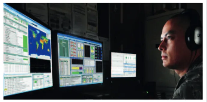
Figure 2. Interaction of operators with the CubeSat through MCC (Braxton Tech 2015).
embedded sot ware components with real time subsystem control are needed (Díaz et al. 2014); in the case of MCC, desktop sot ware applications are required, whereby it is possible to control the devices of the ground station (GS) communications system (Díaz et al. 2015).
h e MCC is the ground system that allows mission operators to manage the SC life cycle operations (Funase et al. 2007). It consists of a series of SW applications that allow the execution of standard operations, such as the SC trajectory prediction or the SC tracking, by rotating antennas in azimuth and elevation values; and also the management of telecommands and telemetry data through communication with UHF/VHF and S-Band radios. In addition, the MCC can integrate SW applications for processing images captured by the payload, using tools such as MATLAB. Front-end applications are also used to display the operation data (Fischer and Scholtz 2010). Figure 2 shows the example of an MCC for a CubeSat mission.
SW elements of the SC and MCC should consider non-functional quality requirements such as reliability, robustness and fault tolerance in their operations (Laizans et al. 2014). h us, the processes of analysis, design, implementation and validation of the elements of the satellite system are a fundamental requirement to the mission and should consider the characteristics of the critical systems. To guide the overall life cycle of the mission and the development of all subsystems, there are two main AM or work proposals that can be used: the SMAD, proposed by NASA, and standards of the ECSS, proposed by the ESA.
SMAD proposes a methodology to develop aerospace missions, beginning with the definition of the objectives of the mission, followed by the design, construction, launch and operation of the SC, and ending with the de-orbit. Its main objective is to guide the development of an aerospace system in a quickly, ei ciently and cheaply way. Its life cycle is based on the dei nition given by NASA in NPR7120.5E (Webster and Corcoran 2007) and consists of seven phases, each dei ned by key decision points(KDP) and a series of major revisions (Puschell 2011). h e purpose of each review varies according to the stage and the section of the mission in which one is working. Four groups of processes are identii ed: (a) Exploration of concepts; (b) Detailed development; (c) Production and deployment; and (d) Operation and support. h e Exploration of concepts results in the dei nition of the mission, its components, cost and schedule. h e Detailed development provides a detailed dei nition of the system, its components and technologies. In the Production and deployment, building of l ight HW and SW and the launch of the SC are performed. Finally, Operation and support is related to the day-to-day space mission, maintenance and closing operations. As SMAD, ECSS proposes a life cycle of seven phases for developing the entire aerospace project. h e ECSS standard covers the main aspects related to development of aerospace systems and seeks to of er a user-friendly guide to the procedures in each of the subsystems.
h e ECSS-E-ST-40C standard from the engineering branch pro-vides guidance for the development of aerospace SW, in which the mission ground segment SW is included. ECSS suggests six major revisions to develop SW: (a) System Requirements Review (SRR); (b) PDR; (c) Critical Design Review (CDR); (d) Quality Review (QR); (e) Acceptance Review (AR); and (f) Operational Readiness Review (ORR), which must be executed during the proposed life cycle, divided into nine groups of processes, which consider requirements dei nition activities, design, implementation and validation of SW: (5.2) sot ware related system requirements process; In the same way that happens with most engineering projects,
(5.4) sotware requirements and architecture design process; (5.5) software design and implementation engineering process; (5.6) sotware validation process; (5.7) sotware delivery and acceptance process; (5.8) sotware veriication process; (5.3) sotware management process; (5.9) sotware operation pro-cess; and (5.10) sotware maintenance process. Each of these processes is responsible for a group of speciic activities of the aerospace sotware development life cycle and produces a series of speciic artifacts that support the documentation (European Cooperation for Space Standardization 2009b).
For the development of commercial SW applications, either embedded type, desktop or web, there are several methods of work, which can be divided into two main categories: agile or robust methodologies.
Agile methodologies are lexible to change, based on close interaction with the customer looking for their feedback; it is not rigid in terms of roles, working groups and ofers only the necessary documentation. Methodologies such as Extreme Programming (XP), Scrum, Lean Sotware Development (LSD), Kanban, Open Uniied Process (OpenUP), Rapid Application
Development(RAD), among others, are being widely used in
recent times for SW application development where a quick-to-market is required (Dingsoyr et al. 2012).
hese methodologies have characteristics like robustness in terms of activities, iterations, tasks, detailed documentation and constant revisions; they are rigid and inlexible and, in the recent decades, have ceased to be used in the commercial ield. However, the RUP, which uses a heavyweight and traditional methodology, is the best known method in SW development (Lopez and Blobel 2009).
he RUP is a full-guided SW engineering methodology with a disciplined approach to assign tasks and responsibilities for the SW development. Its goal is to ensure the production of SW with high -quality attributes that meet the needs of the inal user within an established budget and schedule. his is an iterative and incremental process that guides the development of a standard SW product focused on architecture and led by the UML (Jacobson et al. 2000).
RUP deines four phases for the development of SW: (a) Inception; (b) Elaboration; (c) Construction;and (d) Transition. Every phase is defined by a milestone; these are: (a) Life cycle Objective Vision; (b) Life cycle Architecture; (c) Initial Operational Capability; and (d) Product Release, which aims to ensure that core worklows (business modeling, requirements, analysis, design, implementation, testing and deployment) evolve evenly over the entire SW life cycle (Jacobson et al. 2000).
ACADEMIC SATELLITE MISSIONS
In the last decade, ater the start of the CubeSat era, several authors have made approaches to frameworks which help to guide the development process of SW pieces as elements of the SC, identifying activities, deining life cycles, general process structures etc.
hese researches (Spangelo et al. 2012, 2013; Kaslow et al. 2015) explain a fully-structured framework based on Model-Based Systems Engineering (MBSE) and Systems Modeling Language (SysML) to guide the modeling of CubeSatmissions, in which both the space segment and the ground segment are considered. Moreover, Kaslow et al. 2014 explains how the MBSE model can be used for a simulation of the operation of a CubeSatusing MATLAB. Anderson et al. (2014) incorporates to it a standard property for the development of business satellites; however, the MBSE model is focused on the system modeling only and does not include the entire development life cycle. Additionally, the framework does not address the ECSS or SMAD methodologies, which guides the development from an aerospace perspective and incorporates neither activities distribution elements nor deined artifacts, such as those presented in RUP, in which management, organization and control processes for the whole sotware project are included.
Huang et al. (2012) explain the use of agile methodologies like SCRUM and XP for development of HW and SW elements of academic satellites and consider as study case the Multi-Mission Bus Demonstrator Project (MBD), conducted by he Johns Hopkins University – Applied Physics Laboratory (JHU – APL). However, any of the characteristics and properties of aerospace development are taken into account.
Asundi and Fitz-Coy (2013) propose a framework for CubeSat mission design based on a systems engineering approach.
he model intends to use a low-downin order to model the
requirements, subsystems operations, components interfaces and tasks lows, but also ignores aerospace development processes. Ziemke et al. (2011) present a framework of SW development for embedded systems in small SC, integrating examples of development tools, programming language, design patterns and concepts of Service Oriented Architecture (SOA), aligned with the ECSS processes, but its purpose is to suggest a technical model in terms of design and programming operations and does not propose activities, deliverables or development phases, related to development management.
small satellite, using a framework that includes the ESCC-E-ST-70 standard and where a life cycle phase with activities and speciic documentation based on experience gained from earlier satellite missions is proposed, something similar to the objective of this study; however, its purpose is not to make an approach to commercial SW development methodology through the proposed model in order to facilitate the assimilation by traditional development engineers. Bürger et al. (2014) present the systems engineering process used to develop the irst Brazilian CubeSat launch platform
called AESP14 and a CubeSatwith the same name, in which
the activities of the project and a series of documents related to engineering systems, technical speciications and procedures are described. Although the described process takes into account the ECSS standard, an approach is not made to any speciic development methodology.
Chaieb et al. (2015) explain how is possible to use the System-of-Systems (SoS) and SOS Engineering (SOSE) methodology to design and operate a CubeSat-type SC; however, it is not focused on the SW for SC subsystems and does not propose a life cycle, activities or artifacts to the development.
Mohammad et al. (2013) propose a systems engineering
framework for the design of CubeSat missions called Open
Space Box Modeling (OPEN-SBM), based on theSystem
Requirements Design (SRD) methodology, in which modeling graphic components are used. Nevertheless, no standard for aerospace development is contemplated.
Finally, Brandstätter and Eckl (2009) present a model for compatibility management in the development of SC components, aligned with ECSS-M-30A standard, based on a multidisciplinary approach to systems engineering. The authors propose activities and processes, as well as the usage of UML for the design; however, the model does not focus on the development of SW elements for an academic SC.
On the other hand, some studies support the academic development of satellites as the axis of the formation of undergraduate, master’s and doctorate students from diferent programs and also as the improvement of educational processes within universities. Schilling (2006) explains the manner in which the development of CubeSat picosatellites has been integrated into the curricula of Computer Science and Spacemaster – Master’s Program in Space Science and Technology at the University of Würzburg and gives as an example the design of the ground control center of one of the CanSat missions. Bürger et al. (2014) describe how the main activities and disciplines of AESP14 mission are coupled with the semester courses of
college, using the program to teach undergraduate students systems engineering concepts applicable to an aerospace mission.
The review of the state-of-the-art allows identifying the existence of several models or frameworks applicable to the development of the various subsystems of an academic SC (HW/SW) and their integration, using as a methodological basis recent systems engineering concepts or theories as MBSE. Nonetheless, there are few focused speciically to provide traditional sotware engineers and ownership of the development process of the SC SW parts. he papers that have this approach contemplate agile methodologies, propose their own frameworks and some of them align the proposed models to aerospace development standards as ECSS. he studies propose from simple organizational structures of mission work teams, low activities proposals and engineering processes to complex project structures that include life cycles, artifacts, activities, and even introduce concepts of design patterns and SW programming. However, ater this literature review, we could not ind a study that integrates the features of a commercial SW development methodology as used in RUP with a methodical proposal of a SW development model for aerospace applications as ECSS, allowing the local engineers in developing countries to use a work guide that eases the development of the diferent SW elements of CubeSat mission, performing speciic activities, consolidating speciic artifacts, and running a series of revisions during the phases of a certain life cycle.
HYBRID-ACADEMIC-AEROSPACE
MODEL FOR SD
he approach of a Hybrid-Academic-Aerospace Model for Sotware Development (H4ASD) aims to provide traditional engineers with the understanding of the diferent processes of aerospace engineering that must be taken into account in the development of SW parts, fundamental in an academic SC. A working model is clear if a life cycle consisting of certain phases is deined, in which a set of activities associated with artifacts or documents by each executed activity is proposed.
this sense, it is ineicient to use them strictly as a methodological guide in the development of academic SC. Although both models, SMAD and ECSS, include the development of the SC along the life cycle of the mission, that is, taking into account the stages of pre-launch, launch and operation, the ECSS standard is a bit more open to describe activities for the development of SW elements in its ECSS-E-ST-40C document.
At present, agile type methodologies are the most used for the development of commercial SW that must be quick-to-market, since their features are fast teamwork, consolidating only the necessary documentation and obtaining functional SW parts. However, these are not robust enough to be applied in the development of aerospace SW. Due to the characteristics of critical systems, the development of SW parts for aerospace missions needs to be supported in suicient documentation, on which it would be possible to make traceability, modiications and new requirements that arise during the development of the SC. If the mission does not have the formality and documentation, like as that provides a heavyweight methodology, it would not be possible to develop future missions with the aim of obtaining knowledge and engineering development. hat work would be lost. Conversely, RUP model, presenting a detailed description of the entire SW life cycle, specifying each of the iterations, artifacts and activities, both in the structural model of the system and the dynamic one, typical characteristics of a
robust model, makes it the best alternative to be applied in the development of aerospace SW. he robustness of RUP is the product of formalism that exists in the documentation process described through its artifacts tree, compared with lightweight (agile) methodologies, where there is much less documentation. Considering the above, the structuring of H4ASD is based on a “match” between ECSS-E-ST-40C model, as aerospace SW approach, and RUP, as commercial SW approach, as well as on identifying their common, comparable and complementary elements, obtaining a ECSS + RUP model.
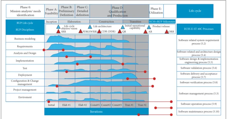
he base of the H4ASD is associated with the similarity between both life cycles and worklows or disciplines. his means that both RUP and ECSS-E-ST-40C suggest similar processes and groups of activities that can be linked to form a single life cycle, to guide the development process. Figure 3 shows the overlap between life cycles, intensity or duration of worklows and respective revisions or milestones in the development process in both models. he top part of Fig. 3 shows the seven stages (0, A, B, C, D, E, F) of the ECSS life cycle project to develop a complete aerospace mission in order to show the way in which RUP and SW development project its within the aerospace project (gray columns).
he characteristics of the RUP’s Inception phase are accura- tely aligned with phase A (Feasibility); Elaboration phase corresponds to the phase B (Preliminary deinition), in which
Figure 3. ECSS-E-ST-40C and RUP life cycles match. Phase 0:
Mission analysis/ needs identification
Phase A: Feasibility
Phase B: Preliminary
Definition
Phase C: Detailed definition
Phase D: Qualification and Production
Phase E: Utilization
Software related system requirement process (5.2) Inception Elaboration
Life cycle
objetive vision Life architecture Initial operational capability Product release ORR AR
QR CDR (DDR) PDR(SWRR)
SRR
Construction Transition ECSS+RUP Milestones
ECSS-E-ST-40C Processes
Software related and archtecture design process (5.4) Software design & implementation
engineering process (5.5)
Software delivery and acceptance process (5.7)
Software verification process (5.8)
Software management process (5.3)
Initial Elab #1 Elab #2 Const#1 Const#2 Const#3 Tran #1 Tran #2 Software operation process (5.9)
Iterations Software maintenance process (5.10)
Software validation process (5.6) Life cycle
Business modeling
RUP Life cycle RUP Disciplines
Requirements
Analysis and Design
Implementation
Test
Deployment
Project management
Enviroment Configuration & Change
the preliminary design of the subsystems is performed, and half of phase C (Detaileddtion), in which th al designs are consolidated; the Construction phase runs between the second half of phase C, in which the lying prototypes of subsystems are manufactured and other mission elements are implemented, and th est half of phase D (Qual ation and Production), in which the full integrated SC is obtained. Finally, there is the SW Transition, which corresponds to the second half of phase D, in which the SC is released and deployed in orbit. he RUP life cycle does not include phase 0 (mission analysis/needs identiication), where the deinition of the mission is carried out, and neither phases E (Utilization) and F (Disposal).
he second part of the match is the association between the RUP disciplines (worklows) and ECSS-E-ST-40C processes. The RUP workflows are represented in duration and inten-sity of activities for each phase (blue curves), considering its iterations, and ECSS represents the processes in extent relative to the total development of SW life cycle (red bars). he RUP business modeling and requirements workflows are similar to the workflow proposed in ECSS-E-ST-40C: 5.2 (software related systems requirement process); the RUP analysis and design worklow is the same process described in 5.4 (sotware requirements and architecture design process); the RUP imple-mentation worklow is analogous to 5.5 (sotware design and implementation engineering process); the RUP test work- low corresponds to 5.6 (sotware validation process); and the RUP deployment worklow aligns to 5.7 (sotware delivery and acceptance process). he additional RUP disciplines or work-lows also coincide with ECSS-E-ST-40C processes. he coniguration and change management low refers to the 5.8 (sotware verii-cation process), and the project management and environment low can be associated to 5.3 (sotware management process). In sotware, veriication processes are intended to conirm if the application is being made based on the design that was approved. For this, it is necessary that efective management of the artifacts that were generated during the analysis design and implemen-tation phases takes place. hus, the coniguration and change management discipline may be associated with 5.8 (sotware veriication process), because it is responsible for managing the process of release of such artifacts, including documentation. On the other hand, the discipline proposed integration tasks are strongly related to the process of SW veriication.
he comparative analysis of the life cycles of both models ends with revisions or milestones that each one suggests. Although the times when they are running are similar — at the end of each
phase —, and some reviews collected similar information, ECSS suggests a greater number of revisions. At the end of the Inception phase, RUP suggests the execution of life objective vision, which is aligned with the ECSS System Requirement Review (SRR). At the end of the Elaboration phase, RUP proposes the life cycle architecture, with a similar purpose to the ECSS PDR. Ater the irst iteration of the Construction phase, ECSS intends to conduct the CDR milestone that is not covered in RUP. hen, at the end of this phase, RUP proposes the initial operational capability, which is aligned with the ECSS QR. Finally, at the end of the Transition phase, an AR is executed by ECSS-E-ST-40C and the product release, by RUP. he last revision proposed by ECSS is the ORR, but its implementation is given for phase E of SMAD in which RUP and the development of SW element must be already completed. RUP deines in general terms a number of activities for each phase of the SW life cycle. he activities are related to one of the diferent disciplines of the methodology, organized as follows: in the Inception phase, the SW scope must be formulated, the main constraints to technological, operational and administrative levels must be deined, a requirements baseline must be consolidated, business cases (use cases) are planned, a candidate SW architecture is synthesized according to the use cases, and inally the preparation of the application development environment is performed. In the Elaboration phase, RUP suggests planning the Construction phase iterations, reining the most critical use cases for the application, reining the proposed architecture, choosing the components that should be developed, selecting those to be reused and picking those which deinitely should be bought; inally, the installation of the development platform must be performed. hen, in the Constructionphase, the irst thing that should be done is the technological, human and time resources management; ater this, in an iterative way, the diferent components must be coded according to a detailed design, and unit testing must be performed to get the irst version of the SW, where a product evaluation must be carried out. Finally, for the Transition phase, RUP suggests executing testing on the entire piece of SW; based on these results, a reinement of the application performance characteristics must be done, correcting bugs and improving usability features. A inal version of the user’s manuals and general documentation must be obtained, the SW deployment process is done, the user’s training is conducted related to the system management, and, inally, an evaluation of the inal product in relation to the vision, scope, limitations and requirements baseline is performed.
systems requirement process (5.2), the standard suggests an analysis of the requirements baseline and makes the deinition of the veriication and SW integration requirements. In the sotware management process (5.3), the SW life cycle, development phases, the checkpoints and the technology budget must be deined, and the development and coding tools must be selected. In the sotware requirements and architecture design process (5.4), the following should be done: to deine the modeling, integration and veriication process, analyze the requirements baseline, and, inally, perform the preliminary design of the SW components. In the sotware design and implementation engineering process (5.5), the following must be performed: to execute the detailed design of the components, design the internal and external communication SW interfaces according to the system, create algorithms (business low) of each of the components, code the lows, build applets, integrate the diferent SW layers, perform functional testing, and, finally, develop the first version of the application manual. For sotware validation process (5.6), the following must be done: to deine components test cases, validate the requirements baseline, run the components test cases, verify SW project documentation, verify the technology budget, and verify the validation regarding the requirements baseline.
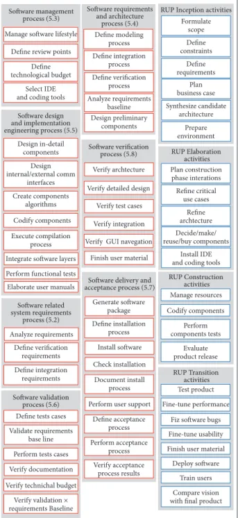
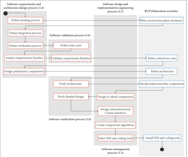
In the sotware delivery and acceptance process (5.7), the following must be accomplished: to create the application installation package, deine the installation process, install the SW in the system, verify proper installation, document the installation process in an installation manual, support operators and users, deine the acceptance process, perform the acceptance activity, and, inally, verify the results of acceptance activity. he last of the ECSS-E-ST-40C processes aligned within the RUP life cycle is the sotware veriication process (5.8), in which the design of test cases, the source code, the integration of the SW layers, and navigation must be veriied — in the case that it is a GS SW element — to, inally, generate the inal version of the application user’s manual. Figure 4 shows all the activities proposed by ECSS-E-ST-40C (red), grouped by process, and the activities proposed by RUP (blue), grouped by phase.
In addition to the proposed revisions and milestones for each working model, both ECSS-E-ST-40C and RUP suggest a basic structure of artifacts that must be generated during SW development project. Although they difer in technical approach, both documentation structures have similar information artifacts that can be linked to create a hybrid artifacts structure in which the approaches of aerospace engineering and SW engineering
are taken into account. Figure 4. Activities proposed by ECSS-E-ST-40C and RUP.
Software management process (5.3)
Software requirements and architecture
process (5.4)
RUP Inception activities
Manage software lifestyle
Design preliminary components Analyze requirements baseline Define verification process Define integration process Define modeling process Formulate scope Define constraints Define requirements Plan business case Synthesize candidate architecture Prepare environment RUP Elaboration activities Plan construction phase interations Refine critical use cases Refine archtecture Decide/make/ reuse/buy components Install IDE and coding tools
RUP Construction activities Manage resources Codify components Perform components tests Evaluate product release RUP Transition activities Test product Fine-tune performance
Fiz software bugs
Fine-tune usability
Finish user material
Deploy software
Train users
Compare vision with final product Define review points
Define technological budget
Select IDE and coding tools
Software design and implementation engineering process (5.5)
Design in-detail components Design internal/external comm interfaces Create components algorithms Codify components Execute compilation process
Integrate software layers
Perform functional tests
Elaborate user manuals
Software related system requirements process (5.2) Analyze requirements Define verification requirements Define integration requirements Software validation process (5.6) Define tests cases
Validate requirements base line
Perform tests cases
Verify documentation
Verify technichal budget
Verify validation × requirements Baseline
Software verification process (5.8)
Verify archtecture
Verify detailed design
Verify test cases
Verify integration
Verify GUI navegation
Finish user material
Software delivery and acceptance process (5.7)
Generate software package Define installation process Install software Check installation Document install process
Perform user support
Define acceptance process Perform acceptance process Verify acceptance process results
th tion of the SW is proposed as part of the mission. In the same way, artifacts as RUP Sotware Architecture Document (SAD) and ECSS Design Deinition File(DDF) can be associated.
In other artifacts, the information is the same in both models, and even their names are the same, for instance, the ECSS Sotware Requirements Speciication (SRS), Sotware Development Plan (SDP) and Software Design Document (SDD), which corresponds to the RUP analysis, design and implementation models. Finally, although most documentation can be linked with each other, some RUP artifacts are so typical of conventional SW development methodology that does not have similar artifacts in ECSS structure, such as SW use case model. Using the comparison results between the two models, a joint work structure for the development of SW parts as elements of an academic-type aerospace mission is deined, in which considerations as critical system properties and SW engineering conventional concepts are taken into account. he H4ASD proposes to execute sequentially and in an interrelated manner the activities proposed in ECSS-E-ST-40C and RUP, on the basis of the RUP life cycle and lows, to which one can associate the execution of diferent ECSS-E-ST-40C processes. It also defines a hybrid artifacts structure in which it is possible to consolidate all SW development project information. Next, the H4ASD is presented, describing the coupling of ECSS-E-ST-40C processes with the RUP life cycle and the hybrid activities lows for each phase. Finally, the structure of artifacts and documentation is provided.
Figure 5. Comparison between ECSS-E-ST-40C and RUP artifacts.
Inception
ECSS-E-ST-40C
ECSS + RUP Aircrafts
Reviews CDR PDR LCA LCOV SRR QR PR AR IOC
Interface Requirements Document ( IRD) Software System Specification ( SSS) Software Requirements Specification ( SRS)
Software Development Plan ( SRS) Interface Control Document ( ICD)
Design Definition File ( DDF)
Software Design Document ( SDD)
Software Source Code and Media Labels Software User Manual ( SUM)
Software Validation Specification ( SVS) Software Verification Plan ( SVerP) ( SVaIP)
Software Release Document ( SRel) Software Configuration File ( SCF)
RUP
Stakeholders request View
Software Requirements Specification ( SRS) Glossary
Business case Risk list Use case model Software Development Plan ( SDP)
Deployment plan Software Archtecture Document ( SAD)
Analysis model Design model Implementation Model Executable Handbooks Test plan Product Installation documents Elaboration Construction Transition RUP Phases
he H4ASD life cycle (Fig. 6) seeks to ease the understanding of diferent aerospace SW development processes suggested by the ECSS-E-ST-40C and the order in which these can be run during the four phases of RUP. In order to see the details of the meaning
Inception
Elaboration
CDR PDR LCA
LCOV SRR
QR
AR PR
IOC Business modeling
Requirements Construction Implementations Deployment Test Project management Enviroment
Analysis and design
Software related system requirements process (5.2)
Software requirements and architecture design process (5.4)
Transition
Software delivery and acceptance process (5.7)
S o ft wa r e v er ific ar tio n p ro ces s (5.8) S o ft wa r e m an ag em en t p ro ces s (5.3)
Software management process (5.3)
Software design and implementation engineering process (5.5)
Software validation process (5.6)
of all abbreviations in the triangles (Fig. 6), consult the ECSS-E-ST-40C document. Considering the results of the comparison between the life cycles of both work methodologies, and not forgetting that both are based on a concept of iterative and incremental execution, the H4ASD life cycle simpliies the working model, combining the disciplines or worklows that are carried out with greater intensity during each phase of RUP with its ECSS-E-ST-40C analogues processes. Although a sequential life cycle is proposed, seeking to facilitate the understanding of the activities order, RUP as a methodology and framework can be supported on models such as waterfall or Vmodel to structure the iterative worklows. Selecting a model (waterfall or V) to map the processes of an aeroespacial framework as ECSS would not be correct because ECSS is also structured as a methodology and not only as a model. he model is only the skeleton of methodology life cycle. Worklows and processes associated with H4ASD RUP phases are described next.
• Inception: In this phase, two ECSS-E-ST-40C processes must be carried out; the (5.2) process, referred to the business modeling and requirements RUP lows, and the (5.3) process, referred to the project management and environment RUP lows.
• Elaboration:At this stage, one should run the
ECSS-E-ST-40C (5.4) process; it is aligned with the RUP analysis and design low.
• Construction: In this phase, two ECSS-E-ST-40C
processes must be performed; the (5.5) process, referred to the implementation low, and the (5.6) process, referred to the RUP test low.
• Transition: In the last phase, the ECSS-E-ST-40C
process to be executed is the (5.7), which is aligned
with the RUP deploymentlow.
he ECSS-E-ST-40C (5.8) and (5.3) processes are more related to the management, control, and organization of SW development project as a whole; so that the implementation of ECSS-E-ST-40C should be done throughout the RUP life cycle.
H4ASD activities correspond to a link the activities proposed by RUP for each of the four phases, and between activities of the ECSS-E-ST-40C processes which are aligned with these phases, according to the life cycle described in Fig. 5, and the results of the previous comparison. he H4ASD proposed in this paper suggests the following integration activities for each RUP phase:
• In the Inception phase, the activities proposed by RUP and the activities suggested in the ECSS-E-ST-40C (5.3) and (5.2) processes are integrated. he low begins with the deinition of the SW management, its life cycle and the
review points (5.3); then, it carries out RUP SW engineering activities, as the deinition of the scope and limitations, the irst version of the business cases (use cases) and the candidate architecture. he most important activity of this phase is the requirements deinition, which must be supported in the activities of (5.2) process, as this not only suggests the deinition of the design requirements as RUP does, but also proposes verification requirements and integration requirements deinition. he (5.2) process is also very speciic in deining the requirements related to Human Machine Interface (HMI), database (DB), real-time processing, security, data formats, among others. Figure 7 shows the low of activities for H4ASD Inception phase.
• For the Elaboration phase, there are the activities sug- gested in the ECSS-E-ST-40C (5.3), (5.4), (5.5), (5.6), and (5.8) processes, which are integrated with the RUP activities low. he main result of the execution of this phase is the detailed design of the SW element, using the results of the irst phase. he (5.4) process is the one with a major role in the Elaboration, since it begins with the deinition of the modeling, integration, testing and test cases processes. Ater this irst part, it starts the design, the reinement of use cases and the components preliminary design. he (5.5) process runs with the components detailed design using UML, and the irst version of program algorithms is created. he inal part of this stage is the preparation and installation of the Integrated Development Environment (IDE); (5.6) and (5.8) processes enable a continuous validation of the major design activities in the phase, such as the reinement of the requirements, architecture and components detailed design. Figure 8 shows the low of activities for the H4ASD Elaboration phase.
Software management process (5.3)
Manage software Life cycle
Define review points
Analyze requirements
Define verification requirements
Define integration requirements
Define constraints Formulate scope
Define requirements
Plan business case
Synthesize candidate architecture
Prepare environment Define technolofical budget
Software related system equirements process (5.2)
RUP Inception activities
Figure 7. Inception phase activities for the H4ASD.
are executed, SW layers (business/logic, user interfaces and data) are integrated to obtain the i rst version of the application, general functional tests are performed on the program, and, i nally, the i rst version of the SW manual is consolidated. h e (5.8) process is executed in parallel for each iteration of coding, verifying the source code, sot ware versions and the i nal product. Figure 9 shows the l ow of activities for the H4ASD construction phase.
• h e Transition phase of the model aims at rei ning the full version of the application, prior to delivery to the customer, that is, prior to the launch of the SC and the start of the operation phase, and it should run in parallel with the integration phase of the mission. In this last workl ow, the activities in ECSS-E-ST-40C (5.6) and (5.8) processes are performed; however, the (5.7) process and the activities of RUP are the most relevant, because they run at i rst on the activities l ow. In the i rst part, one must perform a rei nement of the SW element in dif erent levels, as performance, usability and also i xing of the bugs found in the results of functional tests. h en, the activities suggested by the (5.7) process, related to the installation, training for users — if it is the case of MCC SW —, and acceptance by the mission leaders, must be completed. h e (5.8) process is important as the i nal part of the Transition l ow, as the i nal stage of SW development project, and as complement for the acceptance activity, proposing to verify
the documentation, the compliance of technological budget and requirements. h e activities of the SW life cycle end with a comparison of the vision outlined at the beginning, in connection with the i nal product, and the verii cation of the acceptance process. Figure 10 shows the activities l ow for H4ASD Transition phase.
h e artifacts structure of the H4ASD shows a connection between the documentation suggested by RUP and ECSS-E-ST-40C throughout the life cycle of the SW element, as seen in Fig. 11.
Most artifacts have the same goal in the presentation of information and can be worked as a single document, such as SRS and the SDP, or the RUP SAD and ECSS DDF.
required that, for each pair of artifacts (Fig. 11), at least one version or each of the documents is built up. However, it is possible to choose which UML diagrams are used to model the sot ware. h e only compulsory diagram is the use case diagram. In order to see the details of the meaning of all abbreviations in the red boxes (Fig. 11), consult the ECSS-E-ST-40C document.
DESIGN OF THE GSCM&C
h e sequence of tasks of the GSCM&C as the main element of the MCC arises due to the movement that the satellite does on a LEO and its relative position with GS at er it has been deployed, resulting in three pass phases: (a) pre-pass; (b)
real-time; and (c) post-pass. In phase (a), the trajectory of the SC should be predicted, and the operator must be allowed to program the telecommands to be sent. In phase (b), the antennas’ auto tracking is activated, pre-programmed telecommands are sent, and their receptions are coni rmed by the SC. h e Beacon and telemetry-on-demand data are received, and, i nally, each of the received parameters is evaluated in relation to their operating ranges in order to determine the state of the SC. In phase (c), the GSCM&C should display on screen the results of the satellite assessment, generate bug reports or alerts, and save the operation data (telecommands, telemetry and OPL) in the DB. Finally, operators must perform the analysis of the SC operation in the pass, using simulations, statistical graphs and data records through the GSCM&C GUI.
Figure 8. Elaboration phase activities for the H4ASD.
Define moeling process
Define integration process
Define verification process
Analyze requirements baseline
Design preliminary components
Define tests cases
Validate requirements Baseline
Plan construction phase iterations
Refine critical use cases
Refine architecture
Decide/make/reuse/buy components Verify architecture
Verify detailed design Design in-detail components
Create components algorithms
Select IDE and coding tools Install IDE and coding tools Design internal/external
Comm interfaces
RUP Elaboration activities Software design and
implementation engineering process (5.5)
Software validation process (5.6) Software requirements and
architecture design process (5.4)
Software verification process (5.8)
SD INCEPTION PHASE
h e purpose of the Libertad-2 mission is to capture images of the Earth’s surface by using an OPL with a multispectral sensor and a set of custom made lenses. h e data that the sensor will deliver will be raw and compressed using the Huf man algorithm and wavelet transforms, so that the processing will take place on the ground through a MATLAB application. h is application should be part of GS MCC. h e data will be downloaded from the SC, by a 2.2-GHz S-Band downlink with a custom protocol, which must be integrated to the UHF/VHF communication. h e GSCM&C should then receive the OPL RAW data and deliver them to MATLAB for reconstruction. To perform specii c tasks as the satellite “tracking”, in which the prediction path of the nanosatellite on LEO and the antennas’ rotation are integrated, it was decided to use the Systems ToolKit (STK), a sot ware application developed by Analytical Graphics Incorporated(AGI) Company. Because the GSCM&C GUI represents the “front-end” of the entire mission,
it was decided to perform a system design based on interaction with 3-D elements, through which the operator can dynamically select the dif erent elements and components of the nanosatellite to display their operating data and thus perform monitoring. From the dei nitions of this activity, the Stakeholders Request (IRD) and Vision (SSS) artifacts were generated.
A list of requirements for each mission subsystem (attitude determination and control subsystem, electrical power subsystem, command and data handling, OPL, Communication subsystem S-Band and UHF/VHF) and an additional list of general
requirements were dei ned. h e consolidated requirements
structure for the development of the GSCM&C is composed of the following groups of requirements: <<Passes data>>, <<Telecommand>>, <<Telemetry>>, <<OPL S-Band>>, <<Beacon UHF/VHF>>, <<GUI Control>> and <<GUI Monitoring>>. From the results of this activity, the SRS artifacts were generated.
Codify components
Execute compilation process
Verify test cases
Verify integrations
Verify GUI navegation Perform functional tests
Elaborate user manuals
Verify source code Integrate software layers
Codify components
Perform components tests
Evaluate product release
Perform tests cases Manage resources
RUP Construction activities
Software verification process (5.8)
Software validation process (5.6) Software requirements and
implementation engineering process (5.4)
In Fig. 12, six primary use cases are shown, associated with two actors: the SW operator and the GS communications radios (UHF/VHF and S-Band). h e operator can perform three main tasks: “Send Data”, “Mission Monitoring”, and “View Payload Images”. For these operations to be executed by the operator, the UHF/VHF radio must be able to send and receive information to and from the SC using the AX.25 protocol, and S-Band radio must be able to receive data from the SC using a custom made link protocol, as shown in the box “COMM”. In addition, the operator must coni gure the system to perform the antennas’ rotation. h is is possible through the use of a commercial “Tracking Application” or by adding records of trajectory calculations made
by the STK. From each one of the primary use cases, “extends” or “include” cases are linked, involving an additional operation for their execution or depending of a prior execution of other operations. From the result of this activity, the glossary,business case, and use case model artifacts were generated.
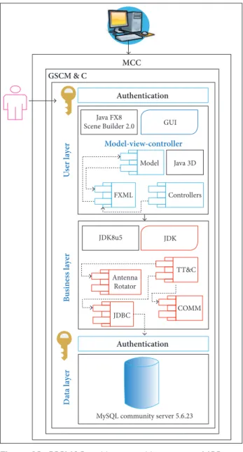
h e GSCM&C must be run on a server, which must be directly connected to the communications devices, such as transceivers and antenna’s rotors. Furthermore, it should implement a DB, in order to save all information obtained from the mission operation. With these elements dei ned, the Libertad-2 GSCM&C architecture is set as shown in Fig. 13. h e system consists of three logical layers, the basic layered model for sot ware development: “User
Figure 10. Transition phase activities for the H4ASD. Generate software package
Define installation process
Install software
Check installation
Document install process
Perform user support
Define acceptance process
Perform acceptance process
Verify acceptance process results
Verify documentation
Verify technichal budget
Verify validation
× requirements baseline Compare vision with final product RUP Transition activities
Software delivery and acceptance process (5.7)
Software verification process (5.8)
Software validation process (5.6)
Test product
Finish user material
Deploy software
Train users Finish user material
Fix software bugs
Stakeholders request
Vision
Glossary
User case model
Deployment plan
Business case
Risk list Software
development plan
Software architecture
document Software requirements specification
Analysis model Design model
Test plan
User manuals
Implementation model
EXE
Srel SCF SUM
SVS SVR SDD
DDF ICD
SDP
SSS IRD
SRS
SVerP SVaiP
Tracking Alternative Application
Mission monitoring GSCM&C
COMM
Send data
Rotate antennas
Manage AX.25/S-Band custom protocols
TX UHF/VHF Telecommands
RX UHF/VHF Telemetry
RX S-bBand data Manage STK data
Receive data
View payload images Operator
Radios <<extend>>
<<extend>> <<include>>
<<include>>
<<include>> <<include>>
<<include>>
<<extend>> <<extend>>
Figure 11. H4ASD artifacts tree.
layer contains all of the robust functional code — in this case, written in Java using the Java Development Kit (JDK8u5). he main components of the sotware are the “CORE” commissioned to the temporary control of the entire system, calculated with respect to the satellite passes over the GS, the control of the antennas in horizontal coordinate system, the link protocol that manages the data transmission and reception using the radios, and inally the “Java Database Connectivity” component, which manages the data control in the repository.
he business and user layers act on the client and the data layer, on the server. his forms a client-server architecture. Although both client and server can run on the same computer, it is also possible to have a separate data engine in a diferent physical server, so that it is possible to connect several client applications to the data structure. From the result of this activity, the SDP and SAD artifacts were generated.
SD ELABORATION PHASE
Figure 14 corresponds to the composite structure diagram for the Libertad-2 MCC. he system can be divided into three main parts: the mission team, the MCC server, and the communication peripheral devices. he mission team refers to the elements that have to interact with the GSCM&C. hese elements have direct inluence on the GS operation, as in the case of the group of light dynamics analysis(GFDA), the system operators (SO), and the group on satellite images research (GSIR),or even an indirectly inluence, in the case of mission directors(MD). Each one has its speciic functions and responsibilities.
The GFDA is the actor in charge of operating the STK sotware; in the SO actor, the users interact directly with the GSCM&C; and the GSIR is in charge of operating MATLAB. he second part of the diagram shows the main components of the GS server, where the STK, the GSCM&C, and MATLAB must be executed. he third part of the diagram represents the
Figure 12. GSCM&C general use cases.
Layer”, “Business Layer”, and “Data Layer”. Each layer operates individually, but interacts with speciic components of the others.
he user layer of the architecture presents data on the screen through a GUI, composed by Extensible Markup Language
(XML) and XML-based(FXML) iles built with a speciic IDE
physical devices that compose the GS, which also becomes in the operational context of the GSCM&C. h e GSCM&C should interact with the S-Band, UHF/VHF rotors, the UHF/ VHF transceiver, and S-Band receiver.
To establish communications between the server and the communication devices, “RS232C”-type serial communications are needed in most cases; the interfaces can be USB or Ethernet, as in the case of some S-Band radios. From the result of this activity, a more complete version of the case model and the i rst version of the SDD were generated as part of the analysis model. In order for station operators to analyze, monitor and process the information downloaded from the satellite, it is required a DB that allows the storage and retrieval of information in a
MCC GSCM & C
Authentication
Authentication
U
ser
l
ay
er
B
us
ines
s l
ay
er
D
ata l
ay
er
Model-view-controller
Java FX8
Scene Builder 2 .0
Java 3D
Controllers Model
FXML
GUI
JDK
TT&C
COMM Antenna
Rotator
MySQL community server 5.6.23
JDBC JDK8 u5
MC C Mission
team
Rotation Tracking
Passes
prediction
GUI MD
GFDA
SO
GSIR
GUI CORE
Image processing Image
decompression
COMM
GSCM&C
MATLAB
Communications
TNC Radios Rotors
STK
GUI
S-Band S-Band S-Band
VHF/ UHF VHF/
UHF UHF/
VHF
Text files
S
er
ia
l
S
er
ia
l
Serial Audio
Ethernet Text file Image file
Figure 13. GSCM&C architecture with respect to MCC.
practical and ei cient way. h e data of the satellite mission rel ect the results of the satellite in operation, so its value is immense. h e CORE module of the GSCM&C centralizes its operation based on the passes predictions that are loaded from the STK, since all sot ware operations during the mission life cycle, especially those having to do with communication, depend on the start, extent, and end data of each pass. h e Entity Relationship Model (ERM) for the Libertad-2 mission GSCM&C consists of i ve functional business chains associated to a principal one called “Passes”. Figure 15 shows one of the i ve functional chains of the ERM: the S-Band reception business chain (1), in which both the frames received by the receiver radio and the RAW image data, associated with a given number of frames, are stored.
h e other chains of functional dependencies in the model are related to: (2) the overall system data and the SC general status; (3) the antennas’ rotation; (4) the telemetry on demand and Beacon data as well as the evaluation of state in each telemetry parameter; (5) the last programmed telecommands and a relationship between sent telecommands and received data. From the result of this activity, the version of SDD was improved as part of the design model.
No_capture
isMosaic
No_pass
Optimal Date
UTC_End
UTC_Begin
Path_JPEG
RAW No_Image
No_Frame
String_Frame
Percentage
isActive
String_COMM Images
S-Band_FRames Composed
by [ *;1]
[ *;1]
[ 1;*]
[ 1;1]
is received
in
Passes
Figure 16 shows the GSCM&C main screen layout, in which
the positioning of the various controls, panels, and data labels
Figure 15. Some entities of the GSCM&C data model.
Figure 16. GUI design for the GSCM&C main window.
was deined, so that the diferent operations and use cases were included. From this window, the access to the telecommands programming, the STK data management, and the monitoring of each of the SC subsystems with a 3-D model interaction were contemplated. he implementation of a dynamic GUI, with visually pleasing elements of user interaction, such as the use of 3-D objects, ensures the usability of the application to perform the tasks of satellite mission monitoring and ground control.
he design of the GUI also provides: the possibility to observe the trajectory prediction data; control of the operating parameters of the GS radios; a window to program the telecommands to send and consult the telemetry data records; observation of the monitoring charts and the tracing of special operations. he version of SDD is improved with the results of this activity.
As show in Fig. 17, the MCC operations low begins with the execution of satellite trajectory simulations in the STK (1). he data provided by the STK must be saved in text iles in a speciic location on the server ile system, in order to be uploaded to the GSCM&C then (2). he irst ile delivery the records of each one of the satellite passes over the GS, specifying the “Start time”, “Stop time”, and the duration of the last pass in seconds. Ater the STK iles are generated, the Operation System (OS) opens the GSCM&C and loads the passes prediction and rotation (AZ/EL) data (3) (4). he “DataManager” entity manages the loaded data using the DB and provides the prediction data to the “TimeControl” entity (5). his entity is responsible for controlling the execution time of each operation during the mission life cycle through the MCC. he OS can program the telecommands to send through the GUI (6), and the “DataManager” feature saves them in the DB (7). At the right time, the “TimeControl” and “AntennaControl” entities are activated, so that these entities begin to track the SC in real time (8).
Figure 17. GSCM&C MCC operations sequence. 1: Generate simulation
GFDA
GSIR SO
2: Generate files
14: Generate image 13: Rebuild image
MATLAB
COMM STK
3: Select STK files 4: Save STK data
C O R E
M C C
G S C M& C
Antenna control PL data manager
11: deliver OPL data 8: Start rotation
Time control Data manager
10: Deliver data
9: Write data 5: Load STK data
7: Save telecommands
12: Generate RAW data GUI
Immediately aterwards, the entity actives the “COMM” module and delivers the Uplink data, so this module begins the transmission (9). In parallel, the “COMM” receives the telemetry, Beacon and OPL data and delivers them to the “DataManager” entity (10), which
organizes the RAW data frames for each individual image (1 1 )
and then generates the correspondingles in a specd location
of the servle system (12). With this operation, the GSCM&C
completes the tasks of the SC real-time phase.
With the RAW iles on the server, the GUI runs the MATLAB program and rebuilds the image of the selected ile (13). MATLAB generates a ile in image format and saves it into a new directory location. hus, the data captured by the nanosatellite OPL can be displayed on the screen of the GSCM&C. Figure 17 shows the flow of the GSCM&C main tasks regarding the MCC, through which it is possible to display the OPL reconstructed images based on the received RAW data. From this activity, the version of SDD was improved as part of the design model.
SD CONSTRUCTION PHASE
he construction phase is directly related to the implementa-tion or coding of the SW element. In the case of the GSCM&C, a complete version of the application must be obtained, in which all the operations deined in the requirements, related to the SC monitoring and control, are included.
For the Libertad-2 GSCM&C implementation, several development applications were used. NetBeans 8.0.1was used
asIDE, MySQL Workbench 6.1 CE was used asComputer
Aided Sotware Engineering (CASE) tool, in order to build the DB Structured Query Language (SQL) script, and the Java
Development Kit(JDK) Standard Edition(SE) 8u51 was used
as primary language. he whole environment was installed on a Windows operating system. his activity results in a deployment diagram corresponding to the GSCM&C implementation model. he implementation of the Liberatd-2 GSCM&C results in a JavaFX application with the following navigation features: the operator can access only with a username and password provided by the (MySQL) DB administrator; when the operator enters into the application, a main window is presented (Fig. 18). In the let side, the Libertad-2 3-D (Java3D) model is displayed, with which the operator can interact using the computer’s mouse or touchscreen in order to visualize general information such as the structure faces temperature, the state of OPL lens, the power from the solar panels, and the output power of the Microstrip antenna. On the right side, operating statistics, such as the number of sent telecommands, the number of received Beacons, the duration of
the last and next pass, the number of received S-Band frames, and other data, is displayed. By using the 3-D model, it is possible to select the diferent hardware components in order to observe the microcontrollers, memories, and sensors operation data in detail, using the telemetry data that have been received by UHF and have been stored in the DB. he subsystems shown in the 3-D model are: the OBC, the ADCS, EPS, OPL, magnetometer, UHF/VHF radio, and the S-Band radio.
If the operator wants to view the data in a more dynamic way, in order to make comparative analysis between the operation of two or more components, with a double-click selection on one of the (PCB) cards in the 3-D model, the application shows the subsystem monitoring panel, in which the operator is able to visualize N customizable charts and the records list of N components simultaneously, as shown in Fig. 19.
At the top of the application, there is a series of tabs controls whereby the operator can access the diferent operations, as the management of STK passes data, the scheduling of telecommands according to six operation modes, the visualization of behavior data in the UHF/VHF radios kit, the visualization of behavior data in the S-Band radios kit, and, inally, the records of historical
Figure 18. Libertad-2 3-D view on the GSCM&C main window.
image captures made by the OPL. As a result of this phase, the program executable iles, the versions of the SRel, SCF, and Sotware User Manual (SUM) documents were obtained.
RESULTS AND CONCLUSION
In order to assess the functionality of H4ASD as a metho- dological tool for developing SW elements for academic satellite missions, some points are discussed ahead, which reflects the scope and limitations on the applicability of the model.
he use of RUP within the approach was aimed in order that traditional engineers, especially computer science engineers, could have clear concepts of sotware engineering that allowed them to easily assimilate and understand the proposed model, when using it for the development of a SW element in an academic-type aerospace mission. Being RUP the best known sotware development model, above the agile methodologies, it is easier for traditional engineers to understand the operation of at least a part of the ECSS standard. In addition, RUP suggests the use of UML, the most used modeling language, which also represents an advantage for the traditional engineer.
he structuring of the RUP elements is very similar to the ECSS-E-ST-40C; however, each one has diferent approaches (aerospace/commercial) that are complementary. his results in a work model in which the conventional sotware engineering concepts are applied using UML, and also the operating constraints of space context are incorporated, which allows the model to be used to guide the development process of both the SC embedded SW and MCC SW pieces.
he H4ASD integrates elements of both models and should not be seen as something that increases the diiculty, because the aim was to help it by taking a sequential life line to organize the activities, i.e. without losing the focus of the iterative and incremental method, an essential feature in order to reine and improve the analysis, design, and implementation models. he low of activities for each phase of H4ASD is sequential, considering that the team for the development of academic satellite missions consists of a small group of students and traditional engineers, where there is not a complex team hierarchy as the commercial aerospace missions; for this reason, a roles model was not contemplated in the H4ASD approach. he description of the GSCM&C development process for the Libertad-2 satellite mission as a study case of the H4ASD was mostly focused on the analysis and design phases, as they
correspond to the most critical phases in the development process. If a design is correct and includes all system operations as an assembly, the implementation will be successful too. he use of 3-D objects in the GSCM&C Look&Field was performed in order that MCC operators could dynamically display and visualize information about Libertad-2 in-orbit operation. his was made following the proposals of design concepts as User Experience (UX) and Getting Real (GR).
he best way to validate the contribution made by the H4ASD is describing the results it has generated in the development of various sotware elements of the Libertad-2 satellite system, including the GSCM&C, which was described as a case study. he H4ASD has allowed students of industrial, electronics, systems, and telecommunications engineering at the University Sergio Arboleda to be able to work together with local project engineers in the development of various sotware elements of the mission, speciically the following:, in the OPL — Hufman algorithm, wavelet transform compression, and OPL embedded control module; in the OBC — the on-board communication module and the C&DH; finally, the image reconstruction sotware for the MCC.
he model was presented to the developing team of the Libertad-2, was successfully received by two experts in aerospace engineering (mission director and engineering dean), and was clearly understood by research professors. It was also presented in the following undergraduate courses: sotware engineering, real-time operating systems, and embedded sotware for satellite applications, with a total of 18 students, of which 12 are currently working with speciic development tasks.
he development process of SW parts from an academic aerospace system runs between A and D ECSS phases, i.e. Feasibility and Qualiication and Production, regardless of the SW development model that is decided to use. In this sense, the SW part must be developed in parallel with the other mission subsystems, with iterative and incremental tasks.
he H4ASD approach allows traditional sotware engineers to easily understand how ECSS-E-ST-40C work model is structured for the development of SW in aerospace missions, as well as all processes, activities, and tasks suggested, using RUP as a comparator.