ABSTRACT: In this research, an experimental investigation was carried out at the International Islamic University Malaysia - Low Speed Wind Tunnel facility on a generic model of a hybrid lifting hull. Based on the historical trends of non-rigid airships, the ineness ratio of the said hull has been selected equal to 4. Free stream velocity was kept at 20 m∙s–1 and, along with the estimation of aerodynamic parameters, longitudinal and lateral stability characteristics were determined over a range of angles of attack from −8° to +12° and angles of sideslip from −10° to +10°. Zero lift coeficient was obtained at −4.2°, and the corresponding value was found to be greater than that at zero angle of attack. The comparison of the experimental results with the existing analytical relationships of wing has revealed that such an airfoil shaped hull cannot be considered as a wing due to 37% less analytical value of lift coeficient than that obtained by CFD simulations of the said hull. Existing equation of form factor of hull for conventional airships was also revisited, and a correction factor equal to 1.16 in the fundamental drag equation of aircraft’s fuselage was also proposed for ineness ratio equal to 4. Trends of the experimental data and comparison of the same with the theoretical calculations and computational results posed some interesting indings. The longitudinal and directional stabilities of a hybrid lifting hull were found to be statically unstable.
KEYWORDS: Aerodynamics, Hybrid airship, Fineness ratio, Static stability, Wind tunnel testing.
Wind Tunnel Testing on a Generic Model
of a Hybrid Lifting Hull
Anwar Ul Haque1, Waqar Asrar1, Asharf Ali Omar2, Erwin Suleiman1
INTRODUCTION
he concept of liting fuselage for aircrat and hybrid liting hull for hybrid airship is derived from nature as a few marine animals do generate aerodynamic lit from the body (Ul Haque
et al. 2016a). Vogel (1994) was among the irst who noticed that, if one looks at a housely or fruit ly from the side, the head, thorax and abdomen also seem to form a non-symmetrical airfoil-latter on the bottom, more rounded on top. Regarding marine animals, there are some cases in which there is a requirement of negative lit (Vogel 2013). For example, ducks have enough air in their plumage so they are awkwardly buoyant and may need negative lit (Prange and Schmidt-Nielsen 1970). Recently, Ul Haque et al. (2015a) argued that the lit generated by the body is perhaps free of cost lit and can be utilized if such a marine animal want to swim at constant level/height in the sea. Additional lit is also required for those light segments like coming out from water, sharp turns etc.
In the ield of aviation, it is not a new concept and, as per the review paper by Wood and Bauer (2011), Vincent Burnelli has earlier designed a number aircrat based on the liting fuselage concept. Perhaps, the liting body designs usually have greater operational lexibility as the adjustment of dynamic lit can accommodate changes in vehicle’s weight due to the burning of fuel. In an earlier reference, Wood (2003) mentioned that, during the period of 1920 to 1955, about 57 aircrat were developed, but these were either single or 2-seat. Other hybrid concepts have aerodynamic lit coming from the wing as well as from the fuselage. his concept was later applied by Santos Dumont (1973) for the design of a winged hybrid airship in which partial
1.International Islamic University Malaysia – Department of Mechanical Engineering – Experimental and Computational Thermoluid Mechanic Research Group – Kuala Lumpur – Malaysia. 2.University of Tripoli – Department of Aeronautical Engineering – Tripoli – Libya.
Author for correspondence: Waqar Asrar | International Islamic University Malaysia – Department of Mechanical Engineering – Experimental and Computational Thermoluid Mechanic Research Group | Jalan Gombak | 53100 – Kuala Lumpur – Malaysia | Email: [email protected]
J. Aerosp. Technol. Manag., São José dos Campos, Vol.8, No 4, pp.467-474, Oct.-Dec., 2016 aerodynamic lit is obtained from the aerodynamic contour of hull; he was the irst to prove this concept by light testing. According to Becker (1958), if we look back in the history, the irst liting-body concepts involved very blunt half cones. Later, the concepts evolved by Saltzman et al. (1999) into higher fineness-ratio cones to achieve the capability of an unpowered horizontal landing. Numerous wind tunnel tests were performed on candidate versions of the half cones and shapes having lattened bottom surfaces. In 1962, Reed and Darlene (1977) have provided the details of an unpowered horizontal landing and controllable light with a miniature lightweight-radio-controlled model of an M2 half-cone configuration. Unfortunately, none of them has explored the airfoil shaped hull from the aerodynamic and stability point of view.
Several studies can be found in the literature starting from the early 1920s, such as Munk (1924) and Rizzo (1924), and the late 1970s and early 1980s, like DeLaurier and Schenck (1979) and Tischler et al. (1981), as well as many others, about the aerodynamic and stability characteristics of airships. However, in the case of hybrid airships, there is limited experimental data available for aerodynamic lit generated by the aerodynamic liting proile of hull (alone) and its stability characteristics. Most of the experimental data is related to the liting bodies of hypersonic vehicles. For example, some experimental data can be found in an old NACA report by Gumse (1967),which is based on W-F2 coniguration. As per Ash (1972), this was a modiied design of M2-F2 with modiications carried out for the aterbody, the control surfaces, and the canopy location. Others include this on NASA HL-20 to develop a preliminary subsonic aerodynamic model for simulation studies of its liting body Jackson and Christopher (1992). Nevertheless, all of these bodies have ineness ratio(λ) greater than 6 and wings blended with the fuselage.
Hybrid airships are among the potential candidates for tourism industry and transportation of agricultural products. Such vehicles also have the potential to reduce the aviation transport gas emissions and many have come up with promising conceptual designs like Aeroscraft (2013), the airship Sky Freighter (Millennium Air Ship Inc. 2012) and Lockheed’s LEMV (Harrison 2010). Unfortunately, the aerodynamics and stability characteristics of airfoil shaped hulls (alone) of airships have not been fully explored yet. One of the probable reasons is due to the non-availability of the experimental data which can reveal its aerodynamic behavior. In the present study, an efort was done to ill this gap by carrying out an experimental
study on a generic model of a hybrid liting hull (HLH). he selection of its λ value was done such that it falls within the known range of non-rigid airships, discussed in detail in the following section.
SELECTION OF FINENESS RATIO
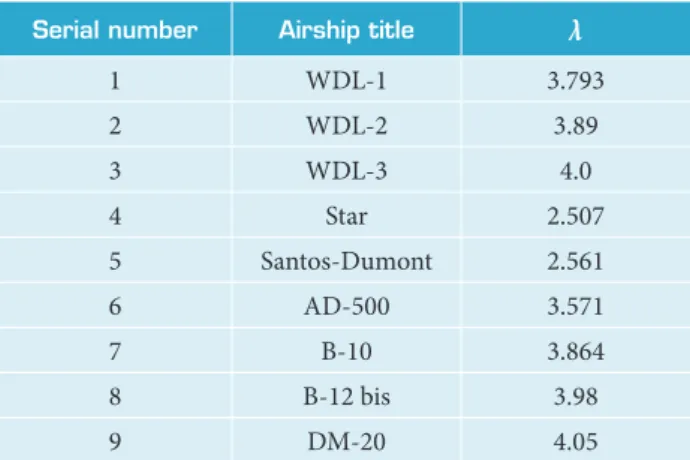
HLH is a type of unconventional hull with voluminous volume for the buoyant lift. It is usually designed to be partially supported by buoyancy lift generated by the buoyant gas while the remaining weight is held up by the aerodynamic lift generated by the aerodynamic contour of the hull (Trenkle 2014). However, the selection of λ is found to be quite trivial, especially in a scenario where there is no guideline/data bank from the historical trends. From the certification point of view, most of the certified airships are flexible in terms of structural anatomy, i.e. non-rigid airships. But from an aerodynamic point of view, high value of λ is always desired. However, a low value is desired for optimum structural weight Tanaka et al. (2005). If we look at the historical trends of non-rigid airships (Table 1), the lowest value of λ was found in the first winged airship, which was designed and flown by Santos Dumont (1973); DM-20, on the other hand,has the highest value.
Serial number Airship title λ
1 WDL-1 3.793
2 WDL-2 3.89
3 WDL-3 4.0
4 Star 2.507
5 Santos-Dumont 2.561
6 AD-500 3.571
7 B-10 3.864
8 B-12 bis 3.98
9 DM-20 4.05
Table 1. Fineness ratio of non-rigid airships.
EXPERIMENTAL SETUP
In order to find the aerodynamic and static stability behavior of a HLHmodel, tests were conducted at the International Islamic University Malaysia - Low Speed Wind Tunnel (IIUM-LSWT)at Reynolds number (Re) equal to 6.3 × 10⁵ against free stream velocity equal to 20 m∙s–1. IIUM-LSWT is a closed-loop wind tunnel with a test section of dimensions 1.5 × 2.3 × 6 m and a maximum achievable speed equal to 50 m∙s–1 (Hasim et al. 2008). The dynamic pressure in the test section varies from −0.5 to 0.4% from the plane mean value, and the flow angularity holds within ±0.2° (Wiriadidjaja et al. 2012).
It is well known that the scaled-down models for the wind tunnel testing are either simpliied or have extra bolts and nuts for attachment purposes, so this drawback of small-scale models cannot reproduce a ditto copy of the full-scale model. herefore, the scaled-down model of HLH of aspect ratio(AR) equal to 0.25 is manufactured in a single piece and polished to get a gloss inish. Such a wooden model cannot be made hollow from side due to issues related to its attachment with the strut.In order to fulill the requirement of blockage ratio, deined by Pope and Rae (1984), the size of HLH model is kept small, and its blockage ratio including that of the strut was just 2.5% of the cross-sectional area of the test section. he model is attached with the strut in the test section by manufacturing an adopter made of stainless steel. However, similarly to any other wind tunnel model, this adopter will create an unavoidable cavity in the model. Hence, it is placed inside the hull body to avoid any additional drag due to model-strut attachment. Moreover, due to the requirement of the estimation of yaw stability parameters, the option of half-model testing is not explored.
Sign conventions are used in the present study such that positive axial force is along the positive x axis (forward from tail to nose), and positive normal force is along the positive z
axis (upwards). he lit and drag coeicients (CL and CD) are
estimated in the wind-axis system, and the results so obtained were plotted without any curve itting — wing span (b) and chord length (c) equal to 0.135 and 0.54 m, respectively. he area (S) equal to 0.042 m2 was the reference parameter used for the data reduction. All the moments were obtained about the moment reference center (MRC) of the balance, which is at 0.14 m from the nose of the HLH. In the case of airships, as well as in the hybrid ones, the gondola is usually located at the base of the hull. herefore, the ofset distance in the vertical
z direction was deined accordingly.
Because the data measured by balance includes the weight components of the model in a special state, it is therefore necessary to deduct the weight components to obtain the real aerodynamic coeicients. he method for deducting the inluence was collecting the measurement data without wind, i.e. wind-of and model-of (W0M0)condition, and then it is deducted in the test matrix. Tests were also conducted to estimate the drag and pitching moment of the strut and fairing, referred here as wind-on and model-of (W1M0)condition. As per the guidelines provided by Tucker (1990) to obtain the real aerodynamic coeicients for wind-on and model-on (W1M1) condition, results so obtained from wind tunnel testing were subtracted from the W1M0and
W0M0 conditions. he pictorial views of tests conducted for
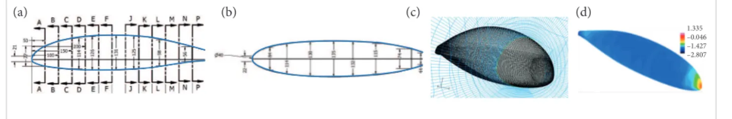
W1M0 and W1M1 conditions are shown in Figs. 1a and 1b, respectively, and the major dimensions of the HLH in the side and top views are shown in Figs. 2a and 2b, respectively.
Figure 1. Pictorial view of W
1M0 and W1M1tests. (a) Strut alone test; (b) Model attached inside the test section.
(a) (b)
Figure 2. Geometric details of HLH along with its surface grid and distribution of pressure coeficient at Re = 6.3 × 10⁵. (a) Side view; (b) Top view; (c) Surface grid; (d) Distribution of pressure coeficient over the hull’s surface.
1.335 –0.046 –1.427 –2.807
J. Aerosp. Technol. Manag., São José dos Campos, Vol.8, No 4, pp.467-474, Oct.-Dec., 2016
RESULTS AND DISCUSSION
AERODYNAMICS AND STATIC STABILITY DERIVATIVES
In order to get the 1st-order approximation of aerodynamics and static stability derivatives of the HLH, the steady-state simulations were run by using ANSYS® FLUENT sotware for which the SIMPLE scheme is employed for pressure velocity coupling along with the k-ω SST model. he details of the geometry used for the mentioned purpose are shown in Figs. 2a and 2b. Structured mesh is generated for the said purpose with additional focus on grid reinement at the nose (Fig. 2c). No slip condition is used for the wall surface. Since the temperature problem is not of interest, the adiabatic wall conditions with no slip boundary condition are employed. Velocity magnitude, along with its direction components, is speciied for the velocity inlet. Outlow boundary is also used, for which all the low variables are basically extrapolated for incompressible low. For subsonic lows, it is required to apply the boundary conditions on the computational domain of radius equal to 20 times the length of the HLH. herefore, the domain extents are kept at 20 times the length of the body to avoid the low variations near the surface. Coupled explicit solver is used with 2nd-order accuracy. All the simulations were run on an Intel® hex-core dual processor, 3.33-GHz system, with 32 GB of RAM, and the results were overlapped with those obtained from the wind tunnel testing (Fig. 3). A stagnation point is observed at the nose of the HLH, as shown from the contours of the pressure coeicient (Fig. 2d).
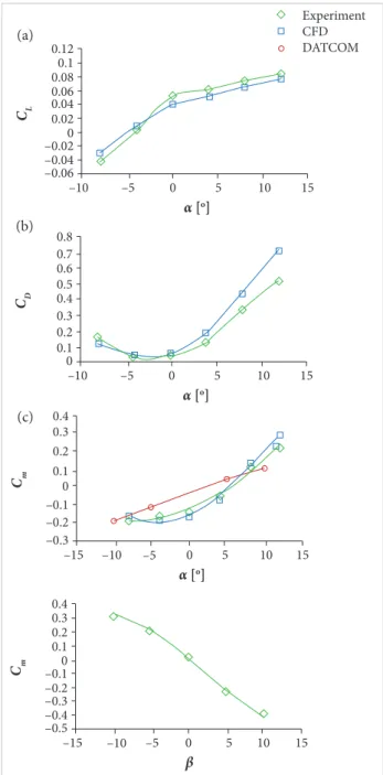
For longitudinal tests (α ≠ 0, β = 0, where α is the angle of attack and β is the side-slip angle), α values were changed from −8° to +12°, and, for β sweep test, the model strut assembly remained rested on tunnel turntable and rotated at a range from −10° to +l0° with 5°-increments. he graphs in Fig. 3 show the trends of aerodynamic and static stability characteristics of HLH in longitudinal as well as in the lateral direction. he lit curve slope (C
Lα) value is obtained by applying the 2nd-order polynomial it on the curve shown in Fig. 3a. Its value comes out to be equal to 0.0067/deg. his igure also shows a continuous increase in CL for a defined range ofα and a reduction in its value for a negativeα. Moreover, there will certainly be a stall value of α beyond 12°; however, if a wing is also attached to it, then the critical value will be that of the wing. hus, the stalling phenomenon which gives rise to reduction in CL and dramatic rise in CDis not observed in these graphs. he angle of attack corresponding to zero-lit condition(αOL)corresponding
to C
Lo condition is equal to −4.2° and its corresponding CD
value, i.e. zero lift drag coefficient (C
Do), is equal to 0.028 (Fig. 3b). It can also be observed from this igure that the CDat zero angle of attack (0.041) was lower than that at zero-lit condition. Moreover, the induced drag is perhaps responsible for high values of CD values at a higher angle of attack.
Figure 3c illustrates the pitching moment coeicient for deined values of the angle of attack. Pitching moment coeicient
Figure 3. Experimental results of aerodynamic and stability coeficients of HLH. (a) Variation in C
L w.r.t α; (b) Variation in C
D w.r.t α; (c) Variation in Cm w.r.t α; (d) Variation in Cnw.r.t β.
–10 –0.06 –0.04 –0.020 0.02 0.04 0.06 0.08 0.1 0.12
–5
α[o]
CL
5
0 10 15
–10 0 0.1 0.2 0.3 0.4 0.5 0.6 0.7 0.8
–5
α[o]
CD
5
0 10 15
–15 –10
–0.3 –0.2 –0.1 0 0.1 0.2 0.3 0.4
–5 α[o]
Cm
5
0 10 15
Experiment CFD DATCOM
–15 –0.5 –0.4 –0.3 –0.2 –0.10 0.1 0.2 0.3 0.4
–5 –10
β
Cm
5
0 10 15
(a)
(b)
J. Aerosp. Technol. Manag., São José dos Campos, Vol.8, No 4, pp.467-474, Oct.-Dec., 2016
exhibits the same behavior as the drag, with a small diference
at negative angles of attack. In addition, the slope of pitching moment (C
mα) is negative for the entire angle of attack range, indicating that it is statically unstable throughout this range.
C
mα is positive and its value is 0.016/deg, indicating that the HLH model under study is longitudinally unstable, and the coefficient of pitching moment at zero lift (Cm
o) is 0.137 (Fig. 3c). It is an important design parameter as it is always added to the Cm
ovalues of other components, such that the total Cmo can be made available for the fundamental stability equation. Similarly to the C
Lα value, the slope of yawing moment coeicient (C
nβ)was also obtained by curve itting and its value is equal to −0.01/deg. An anomaly was seen for the β sweep curve, i.e.
an unsymmetric pattern in the value of the yawing moment coeicient (Cn) for positive and negative β was observed. One of the probable reasons is due to the asymmetry in the model, made of wood. All these results are presented in Table 1 for quick reference.
Wind tunnel testing always reflects the real flow over deined shape with the help of reliable data. Such results can be employed to develop as well as to check the applicability of known analytical relationships. herefore, the experimental results are then compared with the existing analytical relationships, specially the slopes.
COMPARISON WITH EXISTING ANALYTICAL RELATIONSHIPS
If we consider HLH as a wing, then C
Lα obtained by using Eq. 1 is equal to 0.00422/deg. It is important to note that Eq. 1, taken from Raymer (2012), will provide C
Lα in per radian, and, for the purpose of comparison of results, this digit has been converted into per degree.
seen in any aircrat. Moreover, the analytical relationships estimated 37% less value of lit coeicient than that obtained by using CFD. herefore, the use of analytical relationship of the wing for estimation of aerodynamic lit produced by liting hull will not be suitable. Experimental data of space shuttles are available, but the AR for such liting body includes the area of wings attached to it. The C
Lα values of M2-F2 (AR= 0.712) and space shuttle prototype (AR= 2.26) are 0.02 and 0.0446/deg, respectively (Paulson et al. 1960). Hence, considering the HLH as a wing planform cannot be justiied for the airfoil shaped hull being investigated for airship.
CD
o is an important parameter required for aerodynamic analysis and design-related studies (Roskam and Lan 1997). Its exact estimation is very important for accurate prediction of performance parameters of any lying vehicle. he analytical expression for CD
o is given in Eq. 2, taken from Nicolai and Carichner (2013). his relationship is basically the function of form factor (FF). For the case of airship’s hull, it was deined with the help of Eq. 3,and, for aircrat’s fuselage, Eq. 4 is usually used.
he C
Lα value predicted by using the above-mentioned relationship is 0.0054/deg. his value is lesser than that predicted by the experiment, which is equal to 0.006/deg. Nevertheless, the experimental value is consistent with that obtained from the computational luid dynamics (CFD) results. he basic diference is due to the fact that this relationship is for estimation of lit produced by the wing (a liting surface) and which considers the wing as a lat plate. In our case, the (liting body) hull is not a lat plate, and a wing with AR equal to 0.25 is hardly
where: Swet is the wetted area and Sref is the reference one, both in m2; C
f is the coeicient of skin friction; Q is the dynamic pressure; FR is the ineness ratio.
Against the calculated value, if Cf is equal to 0.00488, considering the hull of airship as fuselage (Eq. 3), then the value of FF comes out to be 2.35, which is quite high when compared withFFequal to 1.94, obtained from Eq. 4 (Raymer, 2012). For airship’s hull of any λ value, this author suggested an adjustment factor of 0.8 in basic drag equation to include scaling efects for the airship’s hull. For the value of Swet/Sref
equal to 2.62, regarding the geometry under study, the values of CD
oobtained by using Eqs. (3) and (4) are 0.029 and 0.024, respectively. he predicted value of CD
o obtained from the CFD was quite high and equal to 0.048. Although, Eq. 3, which is taken from Nicolai and Carichner (2013), is not really a FF by the same deinition as used by Hoerner (1965), but it has provided
(1)
(2)
(3)
(4)
C Lα=
πAR 2+ 4+AR
S
α
α
∂β
∂α
α
α
π
C
D0=
f Q
Sw e
Sref
1
α
α
∂β
∂α
α
α
π
1
3
2
+
α
α
∂β
∂α
α
α
π
FF 1+
+
1
α
α
∂β
∂α
α
J. Aerosp. Technol. Manag., São José dos Campos, Vol.8, No 4, pp.467-474, Oct.-Dec., 2016 472 Haque AU, Asrar W, Omar AA, Suleiman E
quite close results to the experimental value. According to a
recent review of FF by Ul Haque et al. (2016b), Eq. 3 is taken from Hoerner (1965), in which the deinition of FF is actually based on a constant frontal area as reference, and the term
Swet/Sref was deined to be equal to 3FR (Eq. 5). In fact, it is a simple adjustment which allows the use of Sreffor the calculation of CD by using Eq. 6:
he pitching moment contribution of the fuselage of general aviation aircrat can be approximated by Eq. 9, taken from Raymer (2012). In this relationship as well, the presence of wing can be observed from the factor C and the reference area of the wing (Sw, in m2).W
f is the maximum width of the fuselage, Lf is the length and Kf is the empirical pitching moment coeicient:
Against the value of FR equal to 4, if we use Eq. 5, then its value is 0.137. This huge digit is due to the fact that Hoerner (1965) had derived the frontal area as reference. Moreover, based on the experimental results and its comparison study, we suggest a correction factor of 1.16 for the FF value obtained by using Eq. 4 and the planform area as reference. It also shows that, in comparison with conventional hull, an airfoil shaped hull will have more drag count.
he comparison of analytical values of Cm
o and Cmα and those obtained from the experimental data is perhaps not straight forward, because the existing relationships add the efect of the wing as well in Eqs. 7 and 8. If we closely inspect these 2 equations, shape efects were considered for the value of Cm
o, but, surprisingly, it has not catered for estimating the value of the slope of pitching moment of the fuselage (C
mα fus) (Ul Haque et al. 2015b).
where:
k
2 – k1 is the correction factor to account for the fuselage slenderness ratio; wf is the average width of the fuselage section, in m; αZLWis the wing zero-lit angle relative to the fuselage reference line, in degrees; Cmα fus is the pitching moment coeicient of the fuselage at zero lit; CMGC is the pitching moment coeicient about the mean geometric chord.
In this case, we use a low-fidelity tool like Aircraft Digital DATCOM®, then the results so obtained reveal that it has underpredicted Cm
o and overpredicted Cmα, when compared with the experimental and computational values. One of the probable reasons is due to the interference of strut with HLH model. On the other side, CFD underpredicted the Cm
ovalue when compared with the experiment, which is equal to −0.187. However, the C
mαvalue obtained from CFD (0.0204/deg) is higher than that of the experiment, 0.0165/deg. The opposite is true when CFD results are compared with the DATCOM® ones. Similarly to C
Lα, Cnβ is obtained and is equal to −0.01/deg. Aircraft Digital DATCOM® does not provide the directional stability contribution at individual angles but provides the value of C
nβ , which is equal to −0.0065/deg for this case of HLH. The comparison of CL and CD is done as Aircraft Digital DATCOM® does not compute lift for an aircraft configuration which has no wing attached to the fuselage. Even if we add a fictitious wing in the hull, based on our experience on similar hybrid lifting fuselage, the lift estimated by CFD is 433.3% higher than that predicted by using the Aircraft Digital DATCOM® , since that produced by the HLH is also responsible for generating the induced drag. Therefore, the comparison of CD is also out of question. However, the same is not true for the case of pitching moment as the analytical relation derived by Munk-Multhopp (see Eqs. 7 and 8) contains the fuselage camber incidence angle (if) to represent the curvature effects of the fuselage (Multhopp 1942).
The wind tunnel test data has provided the aerodynamic as well as static stability characteristics of an HLH. This data can be used in flight performance estimation and system design of hybrid buoyant aerial vehicles. Except for the value of CD, the CFD results underpredicted the lift and pitching moment coefficients. Moreover,
additional combinations of pitch and yaw angles can also be analyzed in the future to be added to the aerodynamic and stability database of such unconventional shaped hull.
CONCLUSION
During αsweep tests, it was observed that the CL was increased with some initial value. If we consider a hull as a wing, then a poor result of lift curve slope is obtained. The existing formula for airship FF has provided quite reasonable comparison with the experimental value. Overall, the CFD results were in good agreement with the wind tunnel ones. Moreover, the HLH is statically unstable in longitudinal and directional modes in the range of specified angles of attack and side slip angles.
ACKNOWLEDGEMENTS
he support of the Ministry of Science, Technology and Inno-vation (MOSTI), Malaysia, under the grant 06-01-08-SF0189, is gratefully acknowledged. he authors are thankful to the team of IIUM-LSWT for providing assistance during the experimental phase.
AUTHOR’S CONTRIBUTION
Haque AU conceived the idea, conducted the experiments and completed the literature review. Asrar W post process the raw data of wind tunnel, drating of the article along with the CFD work for the purpose of comparison of the experimental data of the test article. Omar AA has done the data analysis and interpretation. Suleiman E discussed the indings of the research work and critical revision of the article.
REFERENCES
Aeroscraft (2013) Launching a new century of aviation innovation; [accessed 2013 Apr 2]. http://www.aerosml.com/imagegallery.html
Ash LG (1972) Flight test and wind tunnel performance characteristics of the X-24A lifting body; [accessed 2016 Aug 26]. http://oai.dtic.mil/oai/ oai?verb=getRecord&metadataPreix=html&identiier=AD0901465
Becker JV (1958) Preliminary studies of manned satellites. Winged conigurations. Proceedings of the NACA Conference on High-Speed Aerodynamics; Hampton, USA.
DeLaurier J, Schenck D (1979) Airship dynamic stability. Proceedings of the AIAA Lighter-Than-Air Systems Technology Conference; Palo Alto, USA.
Gumse B (1967) Low-speed wind-tunnel tests of a full-scale M2-F2 lifting body model. NASA TM X-1347.
Harrison J (2010) Lockheed’s LEMV consolation; [accessed 2012 May 8]. http://edgeighter.com/2010/06/17/lockheeds-lemvconsolation
Hasim F, Rusyadi R, Surya WI, Asrar W, Omar AA, Mohamed Ali JS, Kafafy R (2008) The IIUM low speed wind tunnel. Proceedings of the 2nd Engineering Conference on Sustainable Engineering Infrastructures Development & Management (EnCon2008); Kuching, Malaysia.
Hoerner SF (1965) Fluid-dynamic drag: theoretical, experimental and statistical information. Bakerield: published by the author.
Jackson EB, Christopher IC (1992) Preliminary subsonic aerodynamic model for simulation studies of the HL-20 lifting body. NASA TM-4302.
Millennium Air Ship Inc. (2012) The airship “Sky Freighter”; [accessed 2012 May 8]. http://www.millenniumairship.com/products.html
Multhopp H (1942) Aerodynamics of the fuselage. NACA-TM-1036.
Munk MM (1924) The aerodynamic forces on airship hulls. NACA-TR-184.
Nicolai LM, Carichner GE (2013) Fundamentals of aircraft and airship design. Vol. 2: airship design and case studies. Reston: American Institute of Aeronautics and Astronautics.
Paulson JW, Shanks RE, Johnson JL (1960) Low-speed light characteristics of reentry vehicles of the glide-landing type. NASA TM-X-67563.
Pope A, Rae WH (1984) Low-speed wind tunnel testing. 2nd edition. New York: Wiley.
Prange HD, Schmidt-Nielsen K (1970) The metabolic cost of swimming in ducks. J Exp Biol 53:763-777.
Raymer DP (2012) Aircraft design: a conceptual approach. 5th edition. Reston: American Institute of Aeronautics and Astronautics.
Reed R, Darlene L (1977) Wingless light: the lifting body story. NASA SP-4220; [accessed 2016 Aug 26]. http://history.nasa.gov/SP-4220/contents.htm
Rizzo F (1924) A study of static stability of airships. NACA Technical Note 204.
Roskam J, Lan CTE (1997) Airplane aerodynamics and performance. Lawrence: DAR Corporation.
Saltzman EJ, Wang KC, Iliff KW (1999) Flight-determined subsonic lift and drag characteristics of seven lifting-body and wing-body reentry vehicle conigurations with truncated bases. Proceedings of the 37th Aerospace Sciences Meeting and Exhibit; Reno, USA.
Santos Dumont A (1973) My airships; the story of my life. New York: Dover Publications. (Original work published in 1904).
J. Aerosp. Technol. Manag., São José dos Campos, Vol.8, No 4, pp.467-474, Oct.-Dec., 2016
and advanced composites for lighter-than-air aircraft. Proceedings of the 56th International Astronautical Congress; Fukuoka, Japan.
Tischler MB, Jex HR, Ringland RF (1981) Simulation of Heavy Lift Airship dynamics over large ranges of incidence and speed. Proceedings of the Lighter-Than-Air Systems Technology Conference; Annapolis, USA.
Trenkle K (2014) Hybrid Certiication Criteria (HCC) for transport category hybrid airships document number: 1008D0122. Revision: C; [accessed 2014 Jun 4]. https://www.federalregister.gov
Tucker VA (1990) Measuring aerodynamic interference drag between a bird body and the mounting strut of a drag balance. J Exp Biol 154:439-461.
Ul Haque A, Asrar W, Omar AA, Sulaeman E, Mohamed Ali JS (2015a) Cambered proile of a California sea lion’s body. J Exp Biol 218:1270-1271. doi: 10.1242/jeb.117556
Ul Haque A, Asrar W, Omar AA, Sulaeman E, Mohamed Ali JS (2015b) Preliminary aerodynamic and static stability analysis for hybrid buoyant aerial vehicles at low speeds using digital DATCOM. Can Aeronaut Space J 61(3):51-60. doi: 10.5589/q16-001
Ul Haque A, Asrar W, Omar AA, Sulaeman E, Mohamed Ali JS (2016a)
Hydrodynamic contour of Steller sea lion — an inspiration for future hybrid buoyant aircraft. Anim Rev 3(1):1-9. doi: 10.18488/journal. ar/2016.3.1/101.1.1.9
Ul Haque A, Asrar W, Omar AA, Sulaeman E, Mohamed Ali JS (2016b) Assessment of engine’s power budget for hydrogen powered hybrid buoyant aircraft. Propulsion and Power Research 5(1):34-44. doi: 10.1016/j.jppr.2016.01.008
Vogel S (1994) Life in moving luids: the physical biology of low. Princeton: Princeton University Press.
Vogel S (2013) Comparative biomechanics: life’s physical world. Princeton: Princeton University Press.
Wiriadidjaja S, Hasim F, Mansor S, Asrar W, Raie ASM, Abdullah EJ (2012) Subsonic wind tunnels in Malaysia: a Review. Appl Mech Mater 225:566-571. doi: 10.4028/www.scientiic.net/AMM.225.566
Wood RM (2003) The contributions of Vincent Justus Burnelli. Proceedings of the 41st AIAA Aerospace Sciences Meeting and Exhibit; Reno: USA.