(Recebido em 02/04/2012; Texto final em 18/09/2012).
(Monitoramento do processo de soldagem de topo por faiscamento)
Yevgenia Chvertko, Mykola Shevchenko, Andriy Pirumov
National Technical University of Ukraine “Kyiv Polytechnic Institute”, Kyiv, Ukraine, [email protected], [email protected], [email protected]
Abstract
Statistical methods of analysis are currently widely used to develop control and monitoring systems for different welding processes.
These methods allow to obtain information about the process including effect of all factors on its results, which is often dificult to
evaluate due to the complexity of the process. The authors made efforts to apply these methods to develop the system for monitoring
the parameters of lash-butt welding in real-time mode. The paper gives brief information about the features of lash-butt welding of
reinforcement bars and some basic limitation of this process application. The main reasons of formation of defects in welded joints
are given as well as analysis of possibility of application of monitoring systems for their determination. The on-line monitoring system
based on neural networks was developed for evaluation of process deviations. This system is believed to be adequate for determination of process violations resulting in disturbances of welding parameter and can be used for prediction of possible defects in the welded joints.
Key-words: Flash-butt welding, Defects in joints, Neural networks, Quality monitoring
Resumo: Análises estatísticas são normalmente utilizadas para desenvolver sistemas de controle e monitoramento de diferentes processos de soldagem. Estes métodos permitem obter informação sobre o processo, incluindo o efeito de todos os fatores sobre o resultado, os quais são difíceis de avaliar devido a complexidade do processo. Os autores do presente trabalho tentaram aplicar estes métodos para desenvolver um sistema de monitoração dos parâmetros da soldagem de topo por faiscamento em tempo real. O artigo dá uma ideia resumida sobre as características do processo de soldagem por faiscamento de vergalhões, assim como some limitações básicas da aplicação do processo. As razões principais para formação de defeitos na junta soldada são apresentadas, assim como a análise da possibilidade da aplicação de um sistema de monitoração para suas determinações. Um sistema em tempo real baseado em redes neurais para avaliar as variações do processo foi desenvolvido e apresentado. Este sistema é considerado adequado para determinar as não conformidades do processo, e pode ser usado para predizer possíveis defeitos na junta soldada.
Palavras-chave: Soldagem de topo por faiscamento, Defeitos, Redes neurais, Qualidade monitoração
1. Introduction
At the present time the welding process is considered to consist
of three operations [1]: the welding procedure speciication,
welding itself and after-welding check. All the operations mentioned require application of different methods of control
and monitring. During the welding procedure speciication
the preparation of parts to be welded is checked as well as
preliminary cleaning, heat-treatment, welding consumables
and process parameters. The process of welding is followed by selective or continuous monitoring. The after-welding
check includes determination of quality parameters, analysis of
posiible reasons of formation of defects and as a result updating
the welding procedure and parameters (if needed).
Evaluation methods based on statistical analysis and statistical
quality control technologies are often used in welding, especially
for after-welding check. Such quality control methods allow to improve the system and organization of control [2]. Statistical
methods do not replace the other methods of control, but they signiicantly improve their effectiveness, adequacy and
economical characteristics.
Every welding process consists of two components: one is determined by the pre-set welding parameters and resources
used, the second one appears due to different physical processes occuring during welding (they depend on the process nature, conditions in which weling is run and all the internal and
external disturbances). It is almost impossible to determine
all such “side” processes, meaning the exact inluence of each factor on the quality of the welded joint cannot be deinitely
Some prospective studies are devoted to evaluation of quality characteristics by energetic parameters of the welding process. This approach is believed to be the most applicable in case of mass production because these parameters are easy to measure without additional equipment and human resources. The analysis results are used mainly for three purposes: to predict the quality
characteristics of the welded joint (possible defects, mechanical properties and geometry), to deine the disturbances occuring
during the process and for continuous process monitoring. Such analysis if often performed by means of intellectual systems which allow to remove the human from the procedure of control and thus to reduce the subjectivity of its results and the process cost. At the present time such monitoring systems are used for
arc welding and resistance spot welding [3, 4].
The objective of this work was to investigate the posibility of
application of methods of statistical analysis as well as artiicial intelligence systems for monitoring of lash-butt welding process
of concrete reinforcement bars. The monitoring will be based on the analysis of energetic parameters of the welding process.
2. The monitoring of the process of lash-butt welding of reinforcement bars
2.1. Technology of lash-butt welding of reinforcement bars in construction of structures of monolithic reinforced concrete
In construction and repair of reinforced concrete structures the different methods of arc welding of concrete reinforcement
are used. The manual and semi-automatic electric arc welding,
bath-arc welding and others have found the widest spreading. It should be noted that at plants and industrial groups of
as-assembled reinforced concrete a lash-butt welding with a continuous lashing is widely used, except the above-mentioned methods. Now, it is one of main methods of producing the butt
joints of concrete reinforcement under the shop conditions.
The lash-butt welding is characterized by a high stable quality of welded joints, almost equal in strength to the parent metal
that makes it possible to increase greatly the reliability and
service life of reinforced concrete structures and to provide the high productivity. The process of welding is performed in
the automatic conditions, combines the assembly and welding operations in a single cycle, does not require application of auxiliary consumables (electrodes, welding wire, luxes, gases, etc.). Moreover, special requirements to the welder’s qualiication are not speciied.
At the present time, special technologies and equipment are being
developed to make it possible to use this welding method in on-site and semi-stationary conditions [6]. The method application is also partially limited by existing quality control procedures [5]. This rises the problem of development of technologies of non-destructive real-time monitoring.
As a rule, the concrete reinforcement, bars of up to 22 mm are joined by the lash-butt welding with a continuous lashing, and the large-diameter bars are joined by using a lashing with
a preliminary resistance preheating. The latter is characterized
by a wide instable HAZ. The lash-butt welding with a pulsed lashing allows joining all the assortment of reinforced bars and has advantages over the above-mentioned methods. Mechanical
characteristics of these steels in hot-rolled state are given in
Table 1, and chemical composition is given in Table 2.
The carried out technological investigations of welding the hot-rolled reinforcement bars made it possible to establish the values of main parameters of welding conditions: adjusting length Ladj,
tolerances for lashing Llash and upsetting Lupset, open-circuit secondary voltage U2o.-c rates of lashing vlash, and upsetting vupset, time of welding and time of upsetting with current tupsetI [6, 8]. The increased sensitivity to heating of heat-hardened
reinforcement bars speciies the additional requirements to
thermal cycles of heating in welding and increases greatly the requirements to the selection of its heating conditions during welding. Using the welding parameters with smaller tolerances
for lashing usually causes the brittle fracture because of an
intensive heat dissipation into welding machine electrodes being cooled. The recent technological investigations resulted in development of welding cycles for heat-hardened reinforcement bars which allow to produce welded joints almost equal in strength to the parent metal [6].
Table 1. Mechanical characteristics of bar reinforcing steels
Steel grade
σ
0.2, MPaσ
t, MPaδ, %
35GS 370 – 500 610 – 670 18 – 30
25G2S 380 – 400 590 – 620 23 – 31
St3Gsp 235 370 - 490 25
Table 2. Chemical composition of bar reinforcing steels, wt.%
Steel
grade C Mn Si Cr Ni S P Cu
35GS 0.20 – 0.29 1.20 – 1.60 0.60 – 0.90 <0.30 <0.30 <0.045 <0.040 <0.30
25G2S 0.30 – 0.37 0.80 – 1.20 0.60 – 0.90 <0.30 <0.30 <0.045 <0.040 <0.30
2.2. Analysis of possibility of application of the system of monitoring for determination of defects
In general the defects in the welded joints of reinforcement bars appear as a result of three main reasons [9]: violation of technological process parameters (including the results of
different disturbances), violation of technology and rules of the
welding equipment operation and internal parent metal defects. Violation of technological process parameters is often a result of
different disturbances (energetic, kinematic and technological). They may result in signiicant difference between the pre-set
and real values of welding parameters even in case of proper welding equipment operation and preparations of parts to be
welded. In general, two variants of process are possible in this case: one causing the decrease of heat input, the second leading
to overheating of bars.
In case of low heat input the plastic characteristics of the welded bars are reduced especially if they were preliminarily heat-hardened. The joint is formed only on the part of butt
and often discontinuities are detected. Mechanical loads cause
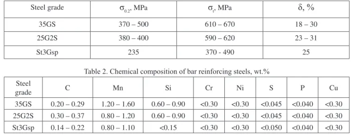
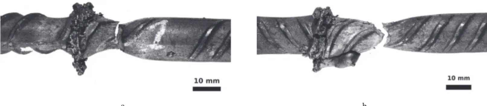
brittle fracture of the weld itself. Typical welded joint fracture and its macrosection are shown on Fig. 1. Overheating of the welded joint results in decreasing of microhardness in the HAZ due to local heat treatment occurring during the welding cycle. Application of the external load causes formation of two necks
proving the hardness loss (see Fig. 2, a). Further increase of
heat-input causes formation of hot cracks in the joint plane. The
structure strength is reduced to 100 … 140 MPa.
Violation of any technological process parameter results in
changes of the electric parameters, meaning the monitoring
system can be effectively used to detect them.
a b Figure 1. The reinforcement bars welded with low heat-input:
a – fracture after tensile tests; b – macrosection
a b Figure 2. The overheated reinforcement bars:
Violation of technology and rules of the welding equipment operation in general lead to disturbances of the welding
parameters in comparison to their values speciied in the welding procedure speciication and also to disturbances related
to improper preparation of parts to be welded.
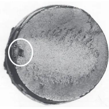
These disturbances are very similar to those caused by the violation of technological process parameters and they result in formation of the same defects in the welded joints. Sometimes the burnt spots are detected on the sides of workpieces reducing the cross-section and causing the strength decreasing (Fig. 3).
As a rule, the burnt spots appear in case of low clamping force or
heavy contamination of current-carrying jaws. In place when the part is not tightly adjacent to the electrode the transient electric resistance is increased to the value exceeding the resistance
of lash gap and the process of a local lashing along the
part-electrode contact surface begins. The formation of burnt spots is also caused by an increased electrical resistance between
the proiled lateral surface of the concrete reinforcement and
electrode.
Violation of technology and rules of the welding equipment operation also result in changes of the welding process parameters making it possible to detect them by means of the monitoring system.
Figure 3. Fracture of reinforcement with a burnt spot
Internal defects of the parent metal (those caused by the process of reinforcement bars production) sometines are also detected in
the welded joints. Mostly they are blackins which are formed
during the bar rolling process. They often appear on the edges
of slabs and blooms as a thick oxide ilm inside the workpiece (see Fig. 4). It is completely impossible to detect such defects
by means of the monitoring system. To prevent their presence in the welded structure a full-scale incoming control of bars should be applied.
Figure 4. Internal defect of the reinforcement bar
2.3. Development of the technology of monitoring for lash-butt welding process
Most of defects which occur as a result of the welding process can be identiied by means of real time monitoring of welding
parameters (without or in addition to after-welding mechanical
testing). In case of lash-butt welding of concrete reinforcement
bars a simple monitoring procedure was used with a single measured parameter – secondary voltage. Welding voltage itself is one of the welding process parameters that is most sensitive to disturbances. The optimal conditions (as described in [6]) as well as three cases of deviation of the process parameters
deteriorating quality characteristics of the joints, which most often occur during welding, such as decrease in workpiece feed
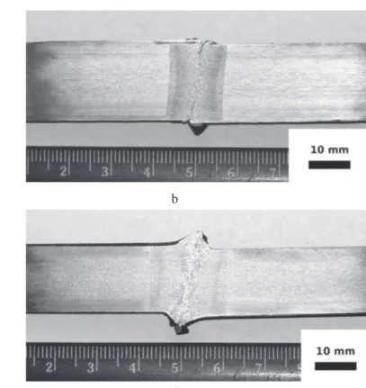
speed vlash, decrease in machine open-circuit voltage U2o.-c, and change in workpiece extension Ladj, were evaluated. The joints produced as a result of the experiments differed in the heating
zone and presence of defects, such as discontinuities (Fig. 5).
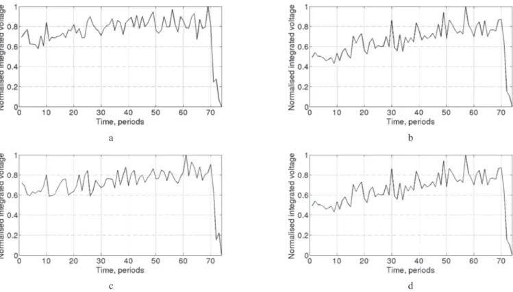
It can be seen from oscillograms of the welding voltage obtained
under different welding conditions (Fig. 6) that the suficiently informative signal relecting the course of the
explosive-spark process is a high-frequency component. The low-pass
Butterworth ilter was applied to reveal this component.
The obtained arrays were divided into blocks equal to ten
periods of the industrial mains voltage (0.2 s), based on permissible duration of deviations during the lashing process [8]. Mathematical expectation of a random quantity module relecting the intensity of lashing at a given stage of oscillogram
was determined for each block. This resulted in the data arrays
a b
c d
Figure 5. Macrosection of the joints produced under different welding conditions: here and below in Figures 6 and 7:
a – optimal conditions, b – decreased speed, c – decreased voltage, d – increased extension
a b
c d
The problem of automatic classii cation of the data arrays can be successfully solved by using neural networks. The Probability Neural Network (PNN) and Learning Vector Quantization (LVQ) were used for classii cation based on the criterion of the
presence of deviation of one of the process parameters (vl ash, U2o.-c, Ladj). The data obtained during experiments were used for
network training, the same training sequence was applied for
both types of networks.
The error in identii cation of disturbances was not in excess of 8 % for LVQ and 13 % for PNN (Fig. 8). This proves a possibility
of the developed system application for most determining of typical distubances of the welding process.
Figure 8. Results of operation of PNN and LVQ networks
a b
c d
Figure 7. Typical data arrays rel ecting the intensity of l ashing for groups of joints
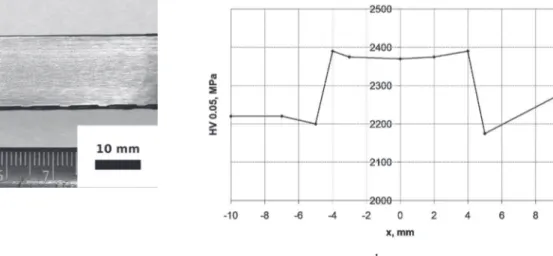
To determine the general quality characteristics for each group of welded joints the mechanical testing of full-scale specimens of joints of hot-rolled reinforcement bars of steel 35GS were performed in accordance with requirements [5]. Fracture of all specimens occurred in the parent metal at a large distance from
the welded joint and HAZ (Fig. 9). Macrosection of the joint and distribution of microhardness (Vickers hardness test, load 0.05 MPa) are shown in Fig. 10, microstructure of zone of joint and
parent metal is given in Fig. 11.
Similar results were obtained also on steels St3Gps and 25G2S in heat-hardened state. The fracture of most specimens (about
90 %) occurred in parent metal beyond HAZ. Macrosection of
such joint and distribution of hardness in it are given in Fig. 12. The mechanical tests have proved that deviations of the parameters of welding process result in the reducing of the joint
quality: the tensile strength reduces, areas with signii cantly
a b
Figure 9. Welded specimens of hot-rolled (a) and heat-hardened (b) concrete reinforcement after tensile tests
a b
Figure 10. Macrosection (a) and distribution of microhardness (b) in the zone of welded joint of reinforcement bar of steel St3Gps
a b
Figure 11. Microstructure of welded joint (a), HAZ (b) and parent metal (c) of reinforcement bar of St3Gps
The developed method of monitoring can be used to predict the defects caused by the violation of technological process parameters. It is also possible to detect disturbances caused by violation of technology and rules of the welding equipment
operation. But in this case the monitoring system will dei nitely
fail to determine the reason of these disturbances. It will classify them as if they were caused by the violation of the
process parameters. In any case, these disturbances will result in formation of the same defects in the joint, so the results of
data analysis will be useful to predict them. The internal defects of the parent metal are completely impossible to be detected by
means of the monitoring procedure developed. To prevent their presence in the welded structure a full-scale incoming control of bars should be applied.
Application of technologies of joining of hot-rolled and heat-hardened concrete reinforcement will make it possible to produce butt joints equal in strength to the parent metal under
the site and semi-stationary conditions, to increase the service life of reinforced concrete structures, to increase their reliability
and to guarantee the high service life. The results obtained
3. Conclusion
1 Application of the system of monitoring of the welding parameters allows to determine disturbances caused by violation of technological process parameters and of technology and rules of the welding equipment operation. Therefore such systems allow to predict related defects in the welded joints. The internal defects of the parent metal cannot be detected by electrical parameters of the welding process.
2. The monitoring of the welding process is based on the analysis of high-frequency component of the welding voltage.
The PNN and LVQ artii cial neural networks are successfully
used for automatic monitoring. Such monitoring systems can be effectively used together with or instead of mechanical tests in industrial conditions to determine the possibility of defect formation in the joint depending on deviances occuring during the joining process.
4. Acknowledgements
The authors wish to thank researchers from the Welding Faculty of the National Technical University of Ukraine “Kyiv
Polytechnic Institute” and from the Department of Pressure Welding of the E.O.Paton Electric Welding Institute for support.
5. References
[1] M. XIE, G. BOLMSJO Quality assurance and control for robotic GMA welding – Part 1: QA model and welding procedure specii cation. Joining Sciences, n. 1(4), 1993, р. 212–220. [2] PIRUMOV, A. E., SHEVCHENKO, M. V., SKACHKOV I.O. Quality monitoring of welding by electric characteristics of process. Scientii c Bulletin, n. 5, 2011, p. 84–88.
[3] SKACHKOV, I.O., PIRUMOV, A. E., MAKSIMOV, S. Yu., PRILIPKO, E. A. On neural network application for welded joint quality control in underwater welding. Paton Welding Journal, n 6, 2006, p. 21
[4] RUDENKO, P. N., GAVRYSH, V. S. System of automatic control of resistance spot welding process KSU KS 02. Paton
a b
Figure 12. Macrosection (a) and distribution of hardness (b) in the zone of welded joint of reinforcement bar of steel 25G2S
Welding Journal, n 11, 2007, p. 43–45.
[5] GOST 10922-90: Reinforced and embedded welded pieces of concrete structures. General specii cation. Moscow: Standart. [6] CHVERTKO, P. N. Flash-butt welding of reinforcement bars of A400s–A600S classes in construction of structures of mono-lithic reinforced concrete. Paton Welding Journal, n 8, 2010, p. 25–28.
[7] DSTU 3760:2006: Reinforced bar for concrete structures. General requirements. General specii cation. Kyiv:
Derzhspozhyvstandart.
[8] KUCHUK-YATSENKO, S. I. (1992) Flash butt welding.
Kiev: Naukova Dumka.
[9] CHVERTKO, P. M., CHVERTKO, Ye. P. Features of l
ash-butt welding of concrete reinforcement bars. Bulletin of Admiral
Makarov National University of Shipbuilding, n. 4, 2010, p.