93
CFD Analysis of airfoils with flaps for low Reynolds
numbers
Manuscript template for the REPA Journal
William D. P. Fonseca 1,3 orcid.org/0000-0001-5184-2193
Max W. F. Reis 1 orcid.org/0000-0002-3482-0854
Pedro F. L. Dias 2,3 orcid.org/0000-0002-5909-2363
Lourival M. S. Filho 2,3 orcid.org/0000-0001-5727-2427
1 School of Mechanical Engineering, University of Campinas, Brazil
2 State University of Maranhão, Brazil
3 Laboratory of Modeling and Numerical Simulation, State University of Maranhão, Brazil
E-mail do autor principal: William Fonseca [email protected]
ABSTRACT
This paper presents a numerical investigation of the aerodynamic flow through airfoils with and without flaps for low Reynolds numbers. A two-dimensional, permanent, viscous model is adopted in the problem. The mass conservation and Navier-Stokes equations are discretized using two numerical methods, the panels method and the finite volume method, using CFD (Computational
Fluid Dynamics) XFLR5® and ANSYS Fluent™ softwares. Initially, the work aims to compare the
results obtained in the numerical simulation for different mesh refining with the analytical model available in the literature. Afterwards, it was verified how the pressure fields, velocity, current lines, drag and carry coefficients for symmetrical and asymmetrical airfoils work. Then, which airfoil is the most aerodynamically efficient, and finally, which numerical method is more feasible for two-dimensional and incompressible aerodynamic simulations.
KEY-WORDS: Aerodynamics; Computational Fluid Dynamics; Flaps. RESUMO
Este artigo apresenta uma investigação numérica do escoamento aerodinâmico através de aerofólios sem e com flap para baixo número de Reynolds. Um modelo bidimensional, permanente e viscoso é adotado no problema. As equações da conservação de massa e de Navier-Stokes são discretizadas utilizando dois métodos numéricos, o método dos painéis e o método dos volumes finitos, através dos softwares CFD (Computational Fluid Dynamics) XFLR5® e ANSYS Fluent™. Inicialmente, o trabalho visa comparar o resultado obtido na simulação numérica para diferentes refinos de malha com o modelo analítico disponível na literatura. Posteriormente, busca-se verificar como se comporta os campos de pressão, velocidade, as linhas de corrente, os coeficientes de sustentação e arrasto para aerofólios simétricos e assimétricos. Em seguida, busca-se verificar qual aerofólio é mais eficiente aerodinamicamente, e por fim, averígua-se qual método numérico é mais viável para simulações aerodinâmicas bidimensionais incompressíveis.
1 INTRODUCTION
Due the continuous enhance in fossil fuels price, aerodynamic studies are conveniently encountered in order to develop better ways to decrease energy consumption of different transportation machines. Researches on models for calculating flows around
aerodynamic surfaces has been growing
exponentially in recent years, this can be credited to the application of these systems in many fields of engineering such as land vehicles, marine vehicles, turbomachinery and aircraft. Abbott and
Von Doenhoff [1] comments that one of the main
applications of aerodynamics is related with the aeronautic area, precisely with global design of airfoils. These equipments are defined by Anderson
[2] as objects of aerodynamic profiles with
constant and two-dimensional section.
The design of an airfoil seeks to support a situation where the aircraft is in prevailing flight, generally level, at cruising speeds and altitudes. However, circumstances such as takeoff and landing may render design conditions unsuitable for describing actual flight situations. In order to attend these different conditions, since the airplanes adopt hyperseting systems, like the flaps,
defined by Brederode [3] as mechanical systems
that change temporally the airfoil’s geometry, in order to produce changes in the flow.
Due to the increasing technological importance of engineering airfoils, a number of tools have been developed gradually to analyze the aerodynamic behavior of these systems, among them the wind tunnel tests and computational simulations, better known as Computational Fluid Dynamics. The wind tunnel tests have some advantages over computational analysis, such as more precise specifications of the surrounding conditions, however, they are still time-consuming procedures with very high costs and also presents series of errors and uncertainties associated to the
experiments that must be studied [4,5]. Numerical
methods, on the other hand, provide faster analysis and lower costs, mainly because of the processing power of digital computers, which makes CFD an important tool in modern aerodynamics.
According to Khayrullina et al., [6], among all
the CFD methods encountered today, the most outstanding in the aeronautics industry are the Panels Method and the Finite Volume Method. The Panels Method solves the non-viscous flow by the
Laplace equation, distributing singularities
(elemental flows) along the body that satisfy the impermeability condition (the flow cannot pass through a solid non-porous surface) and the Kutta
Condition [7]. The Finite Volumes Method consists
in integrate differential conservation equations. For this, the solution domain is divided into a number of control volumes, and the conservation equation
is applied to each of these volumes [8]. Wang [7]
affirms that the computational nodes are located in the center of the control volumes and the variables values can be found in the volume boundary by interpolation of the nodal results. As a result, it is obtained an algebraic equation for each volume.
The present work aims to numerically analyze the flow and the aerodynamic characteristics in two airfoils, one being symmetrical and the other asymmetrical with the presence of flaps. The work also aims to compare which numerical method (Panels Method or Finite Volumes) is more feasible and present results closer to those presented in the literature. For that, the simulations were carried out with software’s that use such methods in their source algorithms.
2 LITERATURE REWIEW
2.1 Panels Method
According to Silva [9] the utilization of
analytical theories in aerodynamic analysis, as Conformal Transformation, are extremely painful for arbitrary geometry bodies, since the high level complexity of the algebraic manipulation. In this kind of application the numerical methods present their advantages, once they can be applied for all geometries, except in specific restrictions.
There is a class of numerical methods very used in aerodynamic which are based in the discretization of the boundary surfaces. These methods are called Boundary Elements Method
[10] and one of them is the Panels Method, very used in the aeronautic industry to the analyses of potential flows through blunt bodies.
Many authors, as Barrett et al., [11] and Kier
et al., [12], consider that the first steps in the development of the Panels Method were given by
Martensen [13]; Hess and Smith [14], which
describe a way of analyzing aerodynamic profiles in potential flows. Such a method allows a wide variety of choice of singularities and their forms of distribution on the discretized surface of the body. A comparative study of these possibilities can be
95
According to Lafaete Jr. [16], the panels
method presents a simple and computationally inexpensive way of calculating the aerodynamic performance. Basically, this method divides the flow into flat plates, calculates the velocities of the flow in these plates and, from there, obtains the pressures along the profile, allowing the evaluation of the aerodynamic forces.
Lafaete Jr. [16] affirms that the calculation of
the tangential and normal velocities of the circudating flow over the airfoil in each panel is given by the Equations (1) and (2).
= = +
+
=
N j N j vij sij j iv
sen
q
u
u
u
1 1
(1)
= = +
+
=
N j N j vij sij j iv
sen
q
v
v
v
1 1
(2)
Where, 𝑢𝑖 is the tangential velocity and 𝑣𝑖 the normal velocity of the panel, 𝛼 is the angle of
attack, 𝑞𝑗 e
, are the singularities intensity of thesources and vortices, respectively. After the calculation of the velocities, the Bernoulli’s principle is applied in relation with the flow in the infinity in order to obtain the pressure distribution:
2
2
2 2 i i i iu
p
v
p
+
=
+
(3)At least, applying these pressures on the panel area, it is obtained the decomposed lift and drag
forces, expressed by Anderson [2] in Equations (4)
and (5).
(
)
=
−
+
=
A i A L LdF
p
sen
dA
F
cos
(4)
(
)
=
−
+
=
A i A D DdF
p
sen
dA
F
cos
(5)
Where, pi is the normal pressure and
theshear pressure of the panel.
This method presents a good approximation for the lift forces, which varies very little with the number of panels adopted. However, the drag has a decreasing behavior as the number of panels increase, which induces a fixed number of panels
in order to realize a comparison among profiles, turning the errors systematic, capable of representing a real trend, although absolute values
have questionable reliability [17].
2.2 Finite Volumes Method
The Finite Volumes Method, described in detail
by Patankar [18], consists in dividing the domain
in a number of non-overlapping control volumes, such that each control volume contains one point of the mesh. A unique equation is then integrated into each control volume.
The discretized equation expresses the properties conservation principles for a finite control volume. The most attractive feature of finite volumes formulation is that the resulting solution implies that the integral conservation of quantities such as mass, momentum and energy is satisfied over any group of control volumes and, obviously, over the entire computing domain. This feature exists for any number of mesh points, not only in the limit case, when the number of mesh points becomes very large. Thus, even for a coarse mesh, the solution exhibits an accurate integral balance.
The governing equations that modulates the aerodynamic flow around bodies are the mass conservation and Navier-Stokes equations. In this, the region of the boundary layer was modeled numerically with a greater degree of refinement of the mesh in region near the surface. These equations are expressed in vector form, for a two-dimensional, incompressible and steady-state flow, as follows:
0
=
•
V
(6)V
g
p
Dt
V
D
=
−
+
+
2
(7)In these equations,
V
indicates the free flowvelocity of the flow, ρ the density, p the pressure,
g the gravity and µ the dynamic viscosity.
Due to the nonlinearities present in the linear momentum conservation equations and the strong pressure, velocity coupling, it is necessary to use iterative strategies for the numerical solution of problems. An alternative is to use the SIMPLE (Semi Implicit Linked Equations) algorithm,
Maliska [19] affirms that it consists of two distinct
satisfy the continuity equation, and in the second, the Pressures are advanced to complement the iterative cycle.
1 MODELING AND SIMULATION
3.1 Description
The computational methodology presented in this work involves the solution of the external flow. The simulations were carried out with the external isothermal air flow, where the solutions of the equations presented in section 3 necessary to obtain the results of the interaction between the fluid and the airfoil were realized with the aid of the
Computational Fluid Dynamics software XFLR5®
and ANSYS Fluent™.
3.2 Modeling using XFLR5
→According to Katz and Plotkin [20], in the
Panels Method, the body surface is discretized into small, straight or curved segments, called panels. The starting and ending points of each panel are called nodes, or nodal points, and the center point is called the control point. On the panels are distributed singularities such as fountains, dipoles or vortices. In this way, the boundary conditions are imposed only at the control points of the panels.
The discretization of the models used in this work were performed using the XFoil code through
XFLR5® software version 6.99. This code is
extremely used to evaluate aerodynamic
characteristics of airfoils and finite wings, and these can occur through several numerical methods, such as LLT (Lifting Line Theory), VLM
(Vortex Lattice Method) and 3D Panels. In this
analysis, a two-dimensional body (airfoil) was discretized by the panel’s method. 800 straight panels were used along the surface of the body, on which vortices were distributed. The initial conditions used in the present work were inserted into the software to simulate flow conditions such as laminar and incompressible. These were the Reynolds number and the Mach number equal to Re = 102 and Ma = 0.0578.
3.3 Modeling using ANSYS Fluent
TM3.3.1 GEOMETRY GENERATION
The geometries were created using the
commercial software Autodesk InventorTM. Such a
choice was based on the easy way when using he 2D modeling tools. For the analysis of fluid
dynamics of the external flow, the ANSYS FluentTM
version 16.0 software was used. Thus, a solid and closed model was created and this was subtracted from within the body volume, thus generating the geometry submitted to the flow. Positioning the geometry within this volume could simulate the actual conditions of interaction between the body and the fluid. This geometry gives the name of the computational domain. The geometries used in the simulations were the NACA 0012 and Eppler 423 airfoils, where the flap was housed at 20% of the trailing edge with deflection of 50°. This deflection was simulated because of the greater efficiency of
an airfoil with flap being between 40° and 60° [2].
3.3.2 MESH GENERATION AND
COMPUTATIONAL METHODOLOGY
VALIDATION
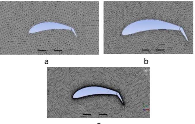
The mesh generation comprises the process of decomposition of the total volume into smaller volumes, allowing the use of the finite volume method to solve the differential equations that govern the problem. In this work, an analysis of the dependence of the computational mesh was made, where we tried to ascertain the refining of this influence in the results when these are compared with those presented in the literature. For the study, three mesh refinement cranes were used, and the meshes generated in the model have
unstructured characteristics with triangular
volumes. Figures 1 (a-c) show the aspects of the meshes generated, while Table (1) explains the number of nodes of each mesh and their respective orthogonal qualities.
a b
c
97
Table 1: Mesh number of nodes. NUMBER OF NODES MAXIMUM ORTHOGONAL QUALITY Figure 4.a refined mesh 89551 89,75 % Figure 4.b intermediate refinement 76282 72,74 % Figure 4.c coarse mesh 19703 53,35 %
The results of the comparative analysis of the models presented previously with the experimental
data exposed by Abbott [21] (Figure 2) showed
that there is a high discrepancy when using the mesh without refinement, it was soon found that the larger the number of elements, the more approximate are the numerical results of the experimental ones. In this way, it was decided to use the refined mesh for simulations.
0 4 8 12 16 20 0,0 0,2 0,4 0,6 0,8 1,0 1,2 C l, l ift c oe ff ic ie nt angle of attack experimental refined mesh
mesh with intermediate refinement coarse mesh
Figure 2: Comparison among different mesh results.
3.3.3 BOUNDARY CONDITIONS
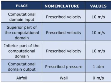
The boundary conditions were sized to simulate the real flow conditions. The contour conditions used in the model are presented in Table (2). These
conditions were obtained from the Fluent [22]
tutorial.
Table 2: Boundary Conditions.
PLACE NOMENCLATURE VALUES
Computational
domain input Prescribed velocity 10 m/s Superior part of
the computational domain
Prescribed velocity 10 m/s Inferior part of the
computational domain
Prescribed velocity 10 m/s Computational
domain output Prescribed pressure 1 atm
Airfoil Wall 0 m/s
4 RESULTS
4.1 Airfoils without flaps
Figures 3 (a-c) show the pressure fields of the airfoil NACA 0012 with different angles of attack, 0°, 10° and 15°, respectively. It is observed there is a symmetry in the pressure field in Figure 3.a, and the stagnation points are located on the leading and trailing edges. This result was expected
since, according to Çengel and Cimbala [23], there
are no pressure gradients for symmetrical airfoils subjected to flow with zero angles of attack. As the angle of attack increases, the pressure gradient becomes favorable (𝜕P/𝜕x <0) in the upper part of the profile and adverse (𝜕P/𝜕x> 0) in the lower part, Figures 3.b and 3.c, this is a consequence of the displacements of the stagnation points.
c
Figure 3: Airfoils without flaps - Pressure field.
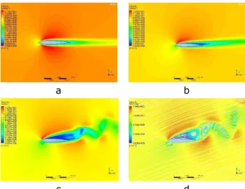
This aspect of the pressure field extends until approximately 15°, where it is perceived that the separation of the boundary layer inverts the pressure field, being this phenomenon a consequence of the formation of vortices in the wake of the flow. Figure 4 (a-d) shows the boundary velocity fields and the flow lines, where the laminar separation of the boundary layer occurs.
The pressure difference in Figs. (3.b) and (3.c) give rise to lift and a linear curve is generated up to the angle of 15°. After this angle there is an abrupt decrease in the coefficient of lift, this is a result of the separation of the boundary layer already explained. Figure 5 shows and compares the curve of this aerodynamic parameter with
Abbott [21].
a b
c d
Figure 4: Airfoils without flaps – Velocity Field.
0 4 8 12 16 20 -0,5 0,0 0,5 1,0 1,5 2,0 2,5 C l, l ift c oe ff ic ie nt , angle of attack Experimental Epller 423(XFLR5) Naca 0012 (XFLR5) Epller 423(Fluent) Naca 0012(Fluent)
Figure 5: Airfoils without flaps – Lift coefficients.
Another analysis that can be obtained from this result is the difference of the coefficients for the two numerical methods used in the simulation. It is verified that the finite volumes method has results closer to the experimental ones, presented
in Abbott [21], this is because the computational
mesh scheme used by this software. Thus, there is a 12% error between the simulated results for the
FVM (FluentTM Software and the panels method
XFLR5®).
For the asymmetrical profile Eppler 423, it is noticed that even with no angle of attack it is generated lift coefficients of this profile are superior to the one of the symmetrical airfoil studied, this is due to its camber (curvature). However, the stall of this profile occurs at angles lower than the airfoil NACA 0012, this is because the geometry of the asymmetric profile. According
to Xi et al [24] this leads to the faster transition of
the boundary layer.
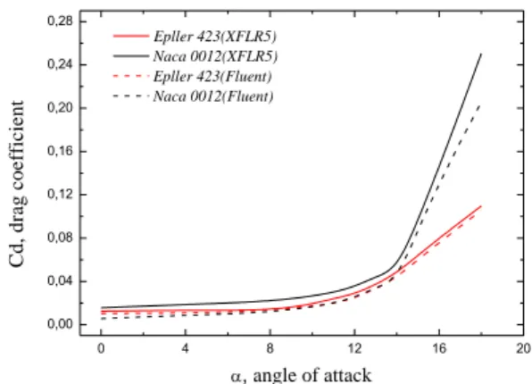
With respect to the drag of these profiles, Figure 6 shows that up to 14° the values are approximate, however above this angle the NACA 0012 airfoil grows more sharply than the Eppler 423. It is also noticed that the error associated with the difference of the numerical method used persists, that is, it is stall 12%.
99 0 4 8 12 16 20 0,00 0,04 0,08 0,12 0,16 0,20 0,24 0,28 C d , d ra g c o e ff ic ie n t , angle of attack Epller 423(XFLR5) Naca 0012(XFLR5) Epller 423(Fluent) Naca 0012(Fluent)
Figure 6: Airfoils without flaps – Drag coefficients.
Analyzing the flap with airfoils, it was found that even at low angles of attack the pressure difference between the upper and lower surfaces of the profiles is very large - Figures 7 (a-c). This causes high values in the lift coefficients.
a b
c
Figure 7: Airfoils with flaps - Pressure field.
It can also be noted that the stall in the airfoil with flap occurs at angles lower than the airfoil without flap, such phenomenon is based on the excessive presence of vortices in airfoils with flaps at low angles, as observed at the field velocity of Figures 8 (a-c). Figure 9 graphically indicates the phenomenon.
a b
c
Figure 8: Airfoils with flaps - Velocity field.
0 4 8 12 16 20 0,5 1,0 1,5 2,0 2,5 C l, l ift c oe ff ic ie nt , angle of attack
Epller 423 with flap Naca 0012 with flap
Figure 9: Airfoils with flaps – Lift coefficients (obtained in Fluent).
About the drag, Figure 10 shows that the symmetrical airfoil has smaller values for small angles of attack. However, for angles above 10 ° this has coefficients greater than those presented by the asymmetric profile.
After all simulations, it was observed from Figure 11 that the asymmetrical Eppler 423 flaps airfoil is the one with the highest aerodynamic efficiency for all angles of attack studied. This is because this profile has better CL/CD ratios for all simulated angles. 0 4 8 12 16 20 0,00 0,04 0,08 0,12 0,16 0,20 0,24 0,28 0,32 0,36 C d, drag c oe ff ic ie nt , angle of attack
Epller 423 with flap Naca 0012 with flap
Figure 10: Airfoils with flaps – Drag coefficients (obtained in Fluent).
0 4 8 12 16 20 0 30 60 90 120 150 C l / C d ( % ) , angle of attack
Epller 423 without flap Naca 0012 without flap Epller 423 with flap Naca 0012 with flap
Figure 11: Airfoil’s aerodynamic efficiency (obtained in
Fluent).
5 CONCLUSION
In this work, the aerodynamic characteristics of airfoils with and without flaps were studied through Computational Fluid Dynamics, the Reynolds number was fixed and the angle of attack varied in order to verify which airfoil and its availability (without or with flap) would be more aerodynamically efficient. It was also studied which numerical method (Finite Volumes or Panels) is more feasible for the realization of two-dimensional simulations in incompressible aerodynamics.
From the results presented in the previous chapters, we arrive at some conclusions:
The simulations showed that when analyzed only the airfoils without flap, the asymmetric one has superior lift coefficient and drag coefficients similar to those presented by the symmetrical profile.
When flap profiles were evaluated, it was verified that the asymmetric in the same way as when the flaps ones had better CL/CD ratios than the symmetrical airfoils. However, it was also found that the stall for the profiles with flap occurs at angles lower than those without it.
It is also concluded that the Eppler 423 profile without flap is the one with the highest efficiency, since this airfoil is the one with the best CL/CD ratio. However, this profile goes into stall at smaller angles than the symmetrical airfoil studied.
Finally, it was observed that FluentTM software
(finite volume method) has a greater robustness with aerodynamic analysis when compared to
XFRL5® (panels method). However, it requires a
higher computational cost.
REFERÊNCIAS
[1] Abbott I. H; Von Doenhoff A. E. Theory of
wing sections, including a summary of airfoil data. New York: Dover Publications, 1959.
[2] ANDERSON JR, J. D. Fundamentals of
aerodynamics. 5. ed. Nova York: Mcgrauw-Hill,
2007. p.1131.
[3] BREDERODE, V. de. Aerodinâmica
incompressível: Fundamentos. Lisboa: IST
Press, 2014. P.735.
[4] ROGERS, S.; ROTH, K.; NASH, S. CFD validation of high-lift flows with significant wind-tunnel effects. In: APPLIED AERODYNAMICS CONFERENCE, 18., 2000, Denver. Procedeeng… Denver, 2000.
[5] JOHNSON, F. T.; TINOCO, E. N.; YU, N. J. Thirty years of development and application of CFD at Boeing Commercial Airplanes. Computers
& Fluids, Seattle, v. 34, n. 10, p. 1115-1151,
2005.
[6] KHAYRULLINA, A. et al. CFD simulation of
train aerodynamics: train-induced wind conditions at an underground railroad passenger platform.
Journal of Wind Engineering and Industrial Aerodynamics, v. 139, p. 100-139, 2015. DOI:
10.1016/j.jweia.2015.01.019.
[7] WANG, H. B et al. Influence analysis of
propeller location parameters on wings using a panel/viscous vortex particle hybrid method. The
Aeronautical Journal, v. 122, n. 1247, p.21-41,
2018.
[8] SHARBATDAR, M.; OLLIVIER-GOOCH, C.
Adjoint-Based Functional Correction for Unstructured Mesh Finite Volume Methods.
Journal of Scientific Computing, v. 76, n. 1,
p.1-23, 2018.
[9] SILVA, D. F. C. Simulação Numérica Do
Escoamento Ao Redor De Aerofólios Via Método De Vórtices Associado Ao Método Dos Painéis. 2005. Dissertação (Mestrado em
Engenharia Mecânica)– Universidade Federal do Rio de Janeiro, Rio de Janeiro, 2005.
[10] BREBBIA, C. A.; TELLES, J. C. F.; WROBEL,
L. C. Boundary Element Techniques: Theory
and Applications in Engineering. Berlin;
Heidelberg: Spring-Verlag, 1984.
[11] BARRETT, R.; ANDREW N. Comparison of
airfoil precomputational analysis methods for optimization of wind turbine blades. IEEE
101
.3, p. 1081-1088, 2016.
[12] KIER, T. M.; MARK J. V; CHRIS W. B. Integrated flexible dynamic loads models based on aerodynamic influence coefficients of a 3. d panel method. Proceedings of the IFASD, 2015.
[13] MARTENSEN, E. The Calculation of the
Pressure Distribution on a Cascade of thick Airfoils by means of Fredholm Integral Equations of the Second Kind. Göttingen:
Aerodynamics Experimental Station, 1959.
[14] HESS, J. L; SMITH, A. M. Calculation of non-lifting potential flow about arbitrary three-dimensional bodies. Progress in Aerospace Sciences, v. 8, p. 1-138, 1967.
[15] PEREIRA, L. A.; HIRATA, M. H.;
MAZANARES, N. Wake and Aerodynamics Loads in Multiple Bodies—Application to Turbomachinery Blade Rows. Journal of Wind Engineering and
Industrial Aerodynamics, v. 92, pp. 477–491,
2004.
[16] LAFAETE JR. Otimização do arqueamento
de dm aerofólio utilizando ligas dom memória de forma. 2013. Dissertação
(Mestrado em Engenharia Mecânica) –
Universidade Federal do Rio de Janeiro, Rio de Janeiro, 2013.
[17] LIMA, J. S. B. Implementação Numérica
do Método dos Painéis Estudo de
Características Aerodinâmicas de Aerofólios. São Paulo: Novas edições acadêmicas, 2016.
[18] PATANKAR, S.V. Numerical Heat Transfer
and Fluid Flow. Boca Raton: Hemisphere
Publishing, 1980.
[19] MALISKA, C. R. Transferência de Calor e
Mecânica dos Fluidos Computacional. 2. ed.
São Paulo: LTC., 2004. p. 453.
[20] KATZ, J.; PLOTKIN, A. Low Speed
Aerodynamics. 2. ed. Cambridge: Cambridge
University Press, 2001.
[21] ABBOTT, I. H. The Drag of Two Streamline
Bodies as Affected by Protuberances and
Appendages. NACA Report, n. 451, p. 171-176, 1932.
[22] FLUENT v6. 3. Fluent Incorporate Inc.,
Centerra Resource Park, 10, Cavendish Court, Lebanon, New Hampshire, USA, 03766, 2006.
[23] ÇENGEL, Y. A.; CIMBALA, J. M. Mecânica
dos fluidos: Fundamentos e Aplicações. São
Paulo: McGrauw-Hill, 2007. p. 816.
[24] XI, H. et al. Numerical simulation of gurney
flaps lift-enhancement on a low Reynolds number airfoil. Science China, China, v. 60, n. 10, p. 1548 – 1559, Oct. 2017.