CONSTRUCTAL LAW &
SECOND LAW CONFERENCE
clc2017.eu
15-16 May, 2017
CLC CONFERENCE
Copyright © Editura Academiei Române, 2017 (The Publishing House of the Romanian Academy)
All rights reserved.
Editura Academiei Române
Address: Calea 13 Septembrie, nr. 13, sector 5 050711, Bucureşti, România
Tel.: 4021-411 90 08, 4021-410 32 00; Fax: 402-410 3983
E-mail: [email protected] Adresa web: www.ear.ro
ISBN: 978-973-27-2748-5 D.L.C. for large libraries: 516(082)
D.L.C. for small libraries: 5/6
Editors: ALEXANDRU-MIHAIL MOREGA and SYLVIE LORENTE Editorial manager: IRINA FILIP
L
IST OF
P
APERS
Title / Authors(s) PAGE
CIRCULAR AND SEMI-CIRCULAR CONSTRUCTAL VASCULAR CHANNELS FOR COOLING AND
REDUCED STRESSES, Erdal CETKIN
1
THE OPTIMAL SPACING BETWEEN DIAMOND-SHAPED TUBES COOLED BY FREE CONVECTION
USING CONSTRUCTAL THEORY, Ahmed Waheed MUSTAFA, Ansam ADIL, Ali RAZZAQ
17
FLOW IS PLEASING AND REMINDS US HOW NATURE WORKS,María Santos BLANCO 30 LOGISTIC LAW OF GROWTH AS A BASE FOR METHOD OF COMPANY LIFE CYCLE PHASES
FORECASTING,Rafał SIEDLECKI, Daniel PAPLA, Agnieszka BEM
45
CONSTRUCTAL THEORY DEVELOPMENTS IN CHINA DURING THE PAST DECADE,Lingen CHEN, Huijun FENG, Zhihui XIE
57
CONSTRUCTAL OPTIMIZATIONS FOR LINE-TO-LINE FLUID NETWORKS IN A TRIANGULAR AREA BY
RELEASING THE TUBE ANGLE,Huijun FENG, Lingen CHEN, Zhihui XIE
94
ANALYSIS OF THE THERMAL PERFORMANCE OF SINGLE- AND MULTI-LAYERED MICROCHANNELS WITH FIXED VOLUME CONSTRAINT, Olayinka Omowunmi ADEWUMI, Tunde BELLO-OCHENDE, Josua MEYER
107
CONSTRUCTAL DESIGN OF FLAT PLATE COLLECTOR, Tanimu JATAU, Tunde BELLO-OCHENDE 126
THE CONSTRUCTAL LAW AS AN APPROACH TO ADDRESS ENERGY EFFICIENCY IN THE URBAN
FABRIC, Sylvie LORENTE
143
CONSTRUCTAL LAW IN THE LIGHT OF LAW OF MOTIVE FORCE, Achintya Kumar RAMANICK 155 CONSTRUCTAL DESIGN OF MOLTEN SALT FLOW AND HEAT TRANSFER IN HORIZONTAL HOLLOW
DISC-SHAPED HEATERS, Wei FU, Hua LIN, Xinzhi LIU, Houlei ZHANG
171
SECOND LAW OPTIMISATION OF AN MTDSTIRLING ENGINE REGENERATOR, James WILLS, Tunde BELLO-OCHENDE
188
THE CONSTRUCTAL THEORY OF INFORMATION, Mark HEYER 208 GEOMETRIC OPTIMIZATION OF A TUBE BANK HEAT EXCHANGER IN A SLOW MOVING FREE
STREAM, Alex FOWLER
232
SCALE ANALYSIS AND ASYMPTOTIC SOLUTION FOR NATURAL CONVECTION OVER A HEATED
FLAT PLATE AT HIGH PRANDTL NUMBERS, Olayinka ADEWUMI, A. DEBUSOYE, Adetunji
ADENIYAN, N. OGBONNA, Ayowole OYEDIRAN
242
CONSTRUCTAL DESIGN APPLIED TO STIFFENED STEEL PLATES SUBMITTED TO ELASTO-PLASTIC
BUCKLING, João Paulo Silva LIMA, Luiz Alberto Oliveira ROCHA, Elizaldo Domingues dos SANTOS, Mauro de Vasconcellos REAL, Liércio André ISOLDI
CONSTRUCTAL APPROACH ON THE FEASIBILITY OF COMPRESSED AIR TEMPERATURE CONTROL BY
VAPORATIVE COOLING IN GAS TURBINE POWER PLANTS, George STANESCU, Ene BARBU, Valeriu VILAG, Theodora ANDREESCU
274
AN ADDITIVE DESIGN METHODOLOGY TO IDENTIFY NONPARAMETRIC HEATSINK, Robin BORNOFF, John PARRY
294
FROM CONSTRUCTAL THEORY UP TO FUNDAMENTAL PRINCIPLES OF HELICAL
GEOMETRODYNAMICS, Cătălina IORDAN, Daniel-Georgel PREDA
309
EVOLUTION AS PHYSICS, Adrian BEJAN 334
CONSTRUCTAL LAW ANALYSIS OF ION TRANSFER IN LIVING CELLS: NORMAL AND CANCER
BEHAVIOR, Umberto LUCIA, Giulia GRISOLIA
348
CONSTRUCTAL INTERDISCIPLINARY AND THE CONCOMITANCE OF THE DYNAMIC VARIATIONS OF THE LIVING TO COGITO-DYNAMICS, Patrick KALASON, Mariem ESSAIDI, Touria ABOUSSAOUIRA
361
GEOMETRICAL OPTIMIZATION OF LOUVER-FIN ARRAYS BY USING CONSTRUCTAL LAW AT LOW
REYNOLDS NUMBER REGIME, Masoud ASADI, Mohamed AWAD
392
THERMODYNAMIC PERFORMANCE EVALUATION FOR HELICAL PLATE HEAT EXCHANGER BASED ON SECOND LAW ANALYSIS, Emad EL-SAID, Mohamed ABDULAZIZ, Mohamed AWAD
418
IS IT THE HESS-MURRAY LAW ALWAYS VALID?, Vinicius PEPE, Luiz ROCHA, Antonio
MIGUEL
444
WHAT IS QUANTUM BIOLOGICAL THERMODYNAMICS WITH FINITE SPEED OF THE CARDIO -PULMONARY SYSTEM:ADISCOVERY OR AN INVENTION?, Stoian PETRESCU, Monica COSTEA,
Bogdan BORCILA, Valeria PETRESCU, Romi BOLOHAN, Silvia DANES, Florin DANES, Michel FEIDT, Georgeta BOTEZ, George STANESCU
456
THE CONSTRUCTAL LAW AS A SCIENTIFIC REVOLUTION, Jack CHUN 469 COMPACT, INTERDIGITATED CONSTRUCTAL DESIGN APPLIED TO SUPERCAPACITOR SYSTEMS, Alexandru MOREGA, Juan ORDONEZ, Mihaela MOREGA, Alin DOBRE
487
AHIGH GRADIENT STATIONARY MAGNETIC FIELD SOURCE GEOMETRY OPTIMIZATION STUDY, Alexandru MOREGA, Alin DOBRE, Mihaela MOREGA, Alina SĂNDOIU
499
OPTIMAL FLUID FLOW CHANNEL ARCHITECTURES IN BIPOLAR PLATES DEDICATED TO THE
OPERATION OF FUEL CELLS IN MICROGRAVITY CONDITIONS, Laurentiu OANCEA, Timur MAMUT, Camelia BACU, Eden MAMUT, Ioan STAMATIN
509
CONSTRUCTAL LAW, AND THE ALBEDO AND GLOBAL WARMING CONUNDRUM, Heitor REIS 518 CONSTRUCTAL NETWORK OF SCIENTIFIC PUBLICATIONS,CO-AUTHORSHIP AND CITATIONS, André Luis RAZERA, Marcelo Risso ERRERA, Elizaldo Domingues dos SANTOS, Liércio André ISOLDI, Luiz Alberto Oliveira ROCHA
ON THE DESIGN AND OPTIMIZATION OF CONSTRUCTAL NETWORKS OF HEAT EXCHANGERS BY
CONSIDERING ENTROPY GENERATION MINIMIZATION AND THERMOECONOMICS, Viorel BADESCU, Tudor BARACU, Rita AVRAM, Roxana GRIGORE, Monica PATRASCU
539
CONSTRUCTAL DESIGN OF A NON-INVASIVE TEMPERATURE BASED MASS FLOW RATE SENSOR FOR ALGAE PHOTOBIOREACTORS, Kassiana RIBEIRO, Juan ORDONEZ, Jose VARGAS, Andre MARIANO
548
REDUCED-ORDER METHANE-AIR COMBUSTION MECHANISMS THAT SATISFY THE DIFFERENTIAL
ENTROPY INEQUALITY, Allen REAM, John SLATTERY, Paul CIZMAS
568
IMMIGRANT ENTREPRENEURSHIP: A PROCESS ILLUSTRATING THE CONSTRUCTAL LAW, Helene Cara CHESTER
592
CONSTRUCTAL DESIGN OF BRANCHED CONDUCTIVITY PATHWAYS INSERTED IN A TRAPEZOIDAL
BODY: A NUMERICAL INVESTIGATION OF THE EFFECT OF THERMAL CONDUCTIVITY AND
CONVECTIVE COOLING ON PATHWAY STRUCTURE, Tadeu FAGUNDES, Neda YAGHOOBIAN, Luiz ROCHA, Juan ORDONEZ
602
A RESEARCH AGENDA: FACILITATING GLOBAL SOCIO-ECONOMIC EQUILIBRIUM THROUGH
ENABLING AND ACCELERATING NATURAL FLOWS --THE CASE OF E-COMMERCE LAW,BITCOIN, AND BLOCKCHAIN, Adrian PETRESCU, Ovidiu PANEA
617
CONSTRUCTAL LAW IN LIGHT OF PHILOSOPHY OF SCIENCE,Marc Elo Risso ERRERA 638 USING CONSTRUCTAL LAW TO DESIGN A VENTILATED WALL FOR ENERGY EFFICIENCY
ENHANCED BY PCM, Guillaume LABAT, Marc MOISSON, Sylvie LORENTE
664
(UN)COMMON RESEMBLANCE, AN ARTIST’S INTERPRETATION OF CONSTRUCTRAL LAW, Christine FORNI
665
INFORMATION TECHNOLOGY FORECAST: BEYOND THE HYPE WITH THE CONSTRUCTAL LAW?,
Stephen PÉRIN
693
OPTIMAL DESIGNED POROUS MEDIA FOR RENEWABLE ENERGY STORAGE, Alexandre MALLEY-ERNEWEIN, Stéphane GINESTET, Sylvie LORENTE
719
DEVELOPMENT OF AN EFFICIENT LOW TEMPERATURE RADIANT HEATING-COOLING SYSTEM, Mohamed MOSA, Matthieu LABAT, Sylvie LORENTE
IS IT HESS-MURRAY LAW ALWAYS VALID?
Vinicius R. Pepea, Luiz A. O. Rochab, Antonio F. Miguelc,d
aDepartament of Mechanical Engineering, Federal University of Rio Grande do Sul, Porto Alegre, Brazil, bMechanical Engineering Graduate Program, University of Vale do Rio dos Sinos (UNISINOS), São Leopoldo, Brazil.
[email protected], [email protected]
cDepartment of Physics, School of Science and Technology, University of Evora, Evora, Portugal, [email protected] d Institute of Earth Sciences (ICT), Pole of Evora, Portugal
Abstract
Complex flow systems such as the vascular and respiratory trees are made of large and small ducts in series. While the literature has reported extensively cases that are in agreement with Hess-Murray law, there are also branching patterns of natural systems that deviate from this law. Is it this deviation to Hess-Murray law possible to predict?In this study, a numerical analysis was carried out to investigate laminar fluid flow of Newtonian and non-Newtonian fluids in T-shaped flow structures with different ratios between the sizes of parent and daughter ducts. The performance of the branching systems was evaluated in terms of total hydraulic resistance and distribution of shear stresses. We showed that the optimal design of a bifurcating ducts not always match a constant reduction factor of 2-1/3 for the duct sizes. The results were compared with
analytical results obtained based on constructal law.
Keywords: tree flow networks, optimal design, Newtonian and non-Newtonian fluids,
Hess-Murray law, power-law fluids, numerical study, constructal law.
1. Introduction
Tree-shaped flow networks have been the subject of numerous investigations owing to its importance in understanding the behaviour of natural systems, and for the design of manmade systems [1-4]. Blood vessels supply cellular tissues with CONSTRUCTAL LAW & SECOND LAW CONFERENCE, 15-16 MAY 2017, BUCHAREST, ROMANIA
cells, nutrients and oxygen, and remove waste products of cellular activity, through branching vascular networks [5]. The respiratory tree supplies oxygen necessary for tissue metabolism and removes the produced carbon dioxide [6]. Tissues, which make up the respiratory zone of this tree, support a very large gas exchange surface between air and blood that is ventilated and perfused with blood. For a fluid transport system the best flow configuration, that connects a point-to-volume or point-to-volume-to-point are tree-shaped, and a compromise must be found between large and small ducts [1-3,7]. For the vascular system, assuming a Hagen–Poiseuille flow through the vessels, Hess [8] and Murray [9] state that the volumetric flow rate must be proportional to the cube of the diameter in a duct optimized to require the minimum work to drive and maintain the fluid. Therefore, the optimal branching is achieved when the cube of the diameter of a parent vessel equals the sum of the cubes of the diameters of the daughters. For symmetric vessels, the ratio between diameters of daughters and parent vessels is 2-1/3
(Hess-Murray law). This optimum way to connect large and small vessels together having rigid and impermeable walls is only valid as long as the flow is laminar, Newtonian, steady, incompressible and fully developed [5,6,10]. Hess-Murray law has also been shown to describe diverse range of biological networks such as capillaries and many small arteries and veins, airways of conducting zone of the respiratory tract, leaf veins of plants, etc.. Larger arteries and veins, and airways of respiratory zone of the lungs, among others, seem do not follow this 2-1/3 rule.
Besides, turbulent flows would not also be expected to obey to law. In fact, Uylings [11] and Bejan et al. [12] showed that turbulent flows require an optimally 2-3/7 rule. However, fluid flow in living organisms is essentially laminar
and evidences suggest that the exposure to turbulent flows might pose some health risk [6].
Blood includes erythrocytes (red blood cells), leukocytes (white blood cells) and thrombocytes (platelets) in an aqueous solution (plasma). Its rheology is largely influenced by the behaviour of the erythrocytes, mainly due to high concentration [5,13]. Blood flow may be considered as steady or pulsatile, Newtonian or non-Newtonian. In small vessels distant from the heart, the flow may be approached as steady. In larger vessels, the flow is pulsatile due to pumping characteristics induced by the heart. Experimental studies suggest that if vessels experiences high shear rates (higher than 100 s-1), it is reasonable to consider blood flow as a
Newtonian fluid [5,13]. However, non-Newtonian effects show up at smaller shear rates in vessels such as the capillaries, small arteries and veins. At shear rates lower than 100 s-1, blood displays shear-thinning behaviour since its viscosity
decreases with increasing shear rate. Revellin et al. [14] and Miguel [5] incorporate in their studies non-Newtonian rheology to achieve the optimum way to connect large and small vessels together.
Fåhræus and Lindqvist [15] observed a significant decrease of apparent blood viscosity in tubes with diameters in the range of 50 – 500 μm (Fåhræus-Lindqvist effect). The reason behind this effect is the formation of a cell-free layer near the wall of the tube, which has a reduced local viscosity (the core of the tube has a higher local viscosity). Blood vessels exhibit diameters from 3 μm to 3 cm, and studies considering this effect on bifurcating design would be needed. Miguel [13] investigated how the optimal branching of parent to daughter vessels is affected by occurrence of Fåhræus-Lindqvist effect.
Although first derived from the principle of minimum work, Hess-Murray law can be obtained in the light of the constructal law [1-3]. This law is grounded on the idea that flow systems are not purposeless (the ultimate target is to persist) and are free to morph in time (evolve), under global constraints. Shape (structure) is the constructal path to carry fluid, heat, mass, etc., to accomplish their purpose. The constructal laws of vessel´s arrangements were derived based on the demand for easier movement, to achieve greater flow access through the generation of a particular design (configuration). Bejan et al. [12] showed that the way to connect large and small vessels together requires a ratio between diameters of daughters and parent vessels of 2-1/3 (Hess-Murray law) and 2-3/7 for laminar and turbulent
flows, respectively. These authors also derived expressions for the branching angles of vessels that facilitate flow access. Relying on the constructal law, and on analytical approaches, the rules of design for flows of non-Newtonian fluids through bifurcating vessels, and for porous-walled vessels were also predicted [5,6]. These rules for connecting large to small vessels together also depend on fluid behaviour index and on wall permeability. Despite its ubiquity in nature, Hess-Murray’s law as a 2-1/3 rule only maximizes access for Newtonian fluids
under laminar flows. Notice that, the rules of design obtained based both on principle of minimum work and on constructal law are based on 1D and 2D analytical approaches. These studies involve many assumptions and simplifications, which are based on justifiable and approximations, listed in [10]. This study aims to obtain new insights into the dynamics of Newtonian and non-Newtonian flows in bifurcating vessels. A 3D numerical study is performed to illustrate fluid flow through T-shaped flow structures. Besides providing a possibility for testing design parameters over a large range of values, the numerical modelling also offers detailed information about the way that the fluid and solid structure interaction occurs. We combine the constructal approach with numerical simulation to analyse these features and to capture the differences between flows profiles in different T-structures. Here, we chart these differences, with the ultimate aim of explaining the features inherent to an easy access to fluid flow.
2. Mathematical Formulation
2.1. Constructal law of design and extremum principles of entropy production It becomes apparent that the emergence of configuration, defined by the constructal law, requires that the entropy changes, rather than staying the same [1-3,16]. Consider that the fluid flow raised to the power of n is proportional to the pressure difference. The rate of entropy generated, Sg, is
n g dS Q p dt T (1)
Here p is the pressure difference (i.e, the potential), Q is the fluid flow (i.e., the current), and T is the absolute temperature. For a Newtonian fluid n=1, the flow is proportional to the pressure difference. In terms of flow resistance R, Eq. 1 may be rewritten as 2 g dS p dt RT or
2 g p R dS dt T (2) 2n g dS RQ dt T or
g
2n T dS dt R Q (3) Maximum flow access means minimum resistance under constraints: constraint of constant p or constraint of constant Q. According to the Eq. 2, minimizing the flow resistance for a specified potential (pressure difference), p, corresponds to maximization of the entropy generation rate. On the other hand, minimizing the flow resistance under a constant current (fluid flow), Q, corresponds to minimizing the entropy generation rate (Eq. 3).2.2. Problem description
Here we consider a T-shaped flow system composed by symmetrical cylindrical ducts. Parent duct bifurcate and its size changes by a certain factor according to
2 D 1 D =a D and 21 L L =a L (4)
where D is the diameter, L is the length, and the subscripts 1 and 2 mean parent and daughter tubes. Here we consider geometries with aD and aL factors between
0.1 to 1.0. The following geometric constraints are taken into account [12]
2 2 1 1 2 2 π D L +2D L =const 4 (5) 1 2 2L L =const (6)
The meaning of Eqs. 5 and 6 is that the total volume occupied by the tubes and the total space occupied by the planar assembly of tubes are fixed.
2.3. Governing equations
The flow is considered to be laminar, steady and incompressible. This 3D flow is governed by the continuity equation,
v 0
(7)
and the momentum equation
v( v) P
(8)
where v is the velocity, is the density, is stress and P is the pressure. The power-law model is used, and an extra-stress tensor is considered
ij ij
(9) Here Z is the rate of deformation tensor, and the viscosity is
n 1 T0 k exp T (10) where T is the temperature, T0 is the reference temperature, is the viscosity, k is
the consistency index, and n is the power-law index. For n=1 this equation becomes the constitutive equation of a Newtonian fluid. For n<1 the fluid exhibits shear-thinning properties, and for n>1 the fluid has shear-thickening properties. The Reynolds number for these power-law fluid flows is defined as [16]
4 3 4 3n 2 n Dn n 2 n 1 4 Re = 3n 1 KD 4n (11)
where ReDn is the generalized Metzner–Reed Reynolds. 2.4. Numerical procedure
The governing Eqs. 7–9 are solved using a finite volume method and employing the segregated method with implicit formulation. The SIMPLE algorithm with under-relaxation was selected for the pressure–velocity coupling. At the inlet a constant mass flow rate is assumed. At the outlet, outflow boundary conditions are used to model flow exits where the details of the flow velocity and pressure are
not known prior to solution of the flow problem, the outflow boundary condition assumes a zero normal gradient for all flow variables except pressure.
On the walls no-slip boundary conditions are applied. For Eq. 8, the convective term is discretized using second-order-upwind scheme in order to obtain sufficiently accurate solutions. In order to obtain a stable and accurate iterative process, the relaxation factors for momentum and pressure were set to 0.70 and 0.30, respectively. The residual values of the governing Eqs. 7 and 8 were all set to 10-4 and 10-6, respectively.
3. Results and discussion
In this section we present a comprehensive set of results to a wider range of power-law indices (i.e., n=0.776, n=1.000 and n=1.100). The generalized Metzner–Reed Reynolds obtained based on Eq. 11 is 100 (i.e., laminar flow). The numerical study was carried out using the following fluids
- Newtonian (n=1): = 1.1405 kg/m3, = 1.9043×10⁻⁵ Pa.s (air)
= 998 kg/m3, = 8.91×10⁻⁴ Pa.s (water)
= 1259.9 kg/m3, = 7.99×10⁻¹ Pa.s (glycerin)
- non-Newtonian: shear-thinning (n=0.776) = 1060 kg/m3;
k = 1.47×10⁻⁴ Pa.sn (blood); shear-thickening
(n=1.100) = 1260 kg/m3; k = 6.60×10⁻³ Pa.sn.
Figure 1.1 Velocity contours (middle plane) for air ( = 1.1405 kg/m3; = 1.9043×10⁻⁵ Pa.s)
across a T-shaped flow structure designed according to D2/D1 = L2/L1= 2-1/3
Figure 1.2 Velocity contours (middle plane) water ( = 998 kg/m3; = 8.91×10⁻⁴ Pa.s)
across a T-shaped flow structure designed according to D2/D1 = L2/L1= 2-1/3
Figure 1.3 Velocity contours (middle plane) glycerin ( = 1259.9 kg/m3; = 7.99×10⁻¹ Pa.s)
across a T-shaped flow structure designed according to D2/D1 = L2/L1= 2-1/3
Figure 2.1 Shear stress contours (top plane) for air ( = 1.1405 kg/m3; = 1.9043×10⁻⁵ Pa.s) in
a T-shaped flow structure designed according to D2/D1 = L2/L1= 2-1/3
Figure 2.2 Shear stress contours (top plane) water ( = 998 kg/m3; = 8.91×10⁻⁴ Pa.s) in a
T-shaped flow structure designed according to D2/D1 = L2/L1= 2-1/3
Figure 2.3 Shear stress contours (top plane) glycerin ( = 1259.9 kg/m3; = 7.99×10⁻¹ Pa.s)
in a T-shaped flow structure designed according to D2/D1 = L2/L1= 2-1/3
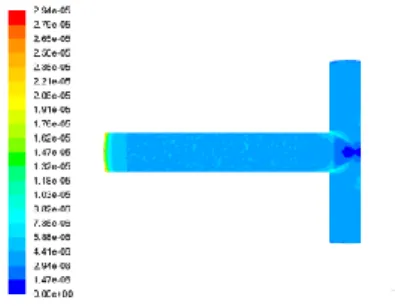
Figure 3 Velocity contours (middle plane) for a shear-thinning fluid (n=0.776, = 1060 kg/m3;
k = 1.47×10⁻⁴ Pa.sn ) across a T-shaped flow
structure designed according to D2/D1 = L2/L1=
2-1/3
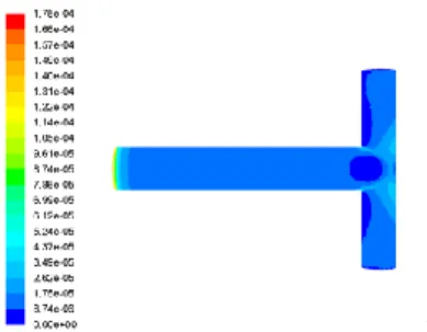
Figure 4 Shear stress contours (top plane) for a shear-thinning fluid (n=0.776, = 1060 kg/m3;
k = 1.47×10⁻⁴ Pa.sn ) in a T-shaped flow
structure designed according to D2/D1 = L2/L1=
Figure 5 Velocity contours (middle plane) for a shear-thickening fluid (n=1.100, = 1260 kg/m3; k = 6.60×10⁻³ Pa.sn ) across a T-shaped
flow structure designed according to D2/D1 =
L2/L1= 2-1/3
Figure 6 Shear stress contours (top plane) for a shear-thickening fluid (n=1.100, = 1260 kg/m3; k = 6.60×10⁻³ Pa.sn ) in a T-shaped flow
structure designed according to D2/D1 = L2/L1=
2-1/3
Figures 1 and 2 show the velocity and shear stress contours for the Newtonian fluids. Although air, water and glycerine have different viscosities and densities, the velocity and the shear stress profiles are similar. We also find that the flow distribution throughout the T-structure is not uniform. This means that for a symmetric bifurcation the flow distribution is asymmetric. This is in agreement with the findings presented in the studies conducted by Andrade Jr et al. [17], and Pepe et al. [10]. The distribution of shearing stress is also significantly heterogeneous in the structure.
Velocity and shear stress contours taken for power law fluids, which include shear thinning and shear thickening, in T-shaped flow geometries are depicted in Figs. 3 to 6. Velocity and shear stress profiles are different for both fluids, and are also different from the profiles observed for Newtonian fluids. In addition, shear thickening fluid flow has in common with Newtonian flows a heterogeneous flow distribution in a symmetric branched assembly of tubes. On the other hand, fluid flow and shear stress distributions are homogeneous for shear thinning flow. It has been found a dependence of flow asymmetric on Reynolds number [10]. Ours study suggest that, for a given Reynolds number, the flow distribution depends on power-law index n.
It would be interesting to study the flow resistance for the T-assembly of ducts. According to Eq. 3, maximum flow access means minimizing the flow resistance under a constant current that corresponds to minimizing the entropy generation rate.
Figure 7 show the total dimensionless flow resistance, R*, for flows of Newtonian and non-Newtonian flow through T-shaped structures. The dimensionless resistance R* is defined as form according to
1/3 D L 2 R R* R (12) where R is total flow resistance defined as the ratio between the pressure difference and the mass flow rate through the T-structure, and RD L 2 1/3 is the
= L2/L1 = 2-1/3. Based on Fig. 7, the geometry that allows the minimum
system-resistance is obtained. Table 1 shows these optimal values and the values predicted analytically by Revellin et al. [14] and Miguel [5].
Figure 7. Dimensionless flow resistance, R*, for a T-shaped structure with impervious walls (K=0 m2): (a) air ( = 1.1405
kg/m3; = 1.9043×10⁻⁵ Pa.s),
(b) water ( = 998 kg/m3; =
8.91×10⁻⁴ Pa.s), (c) glycerin (
= 1259.9 kg/m3; = 7.99×10⁻¹
Pa.s), (d) non-Newtonian fluid ( = 1060 kg/m3; k = 1.47×10⁻⁴
Pa.s, n=0.776), (e) non- Newtonian fluid ( = 1260 kg/m3; k = 6.60×10⁻³⁴ Pa.s,
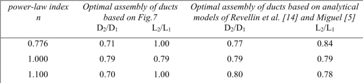
n=1.1) Table 1. Optimal branching sizes for a T-shaped assembly of ducts
power-law index
n Optimal assembly of ducts based on Fig.7 Optimal assembly of ducts based on analytical models of Revellin et al. [14] and Miguel [5]
D2/D1 L2/L1 D2/D1 L2/L1
0.776 0.71 1.00 0.77 0.84
1.000 0.79 0.79 0.79 0.79
1.100 0.70 1.00 0.80 0.78
According to Table 1, there is a difference between results obtained based on analytical models and on our numerical study. In an attempt to understand these discrepancies, our numerical results are used to estimate the flow resistance in different location of the T-assembly of ducts (Table 2).
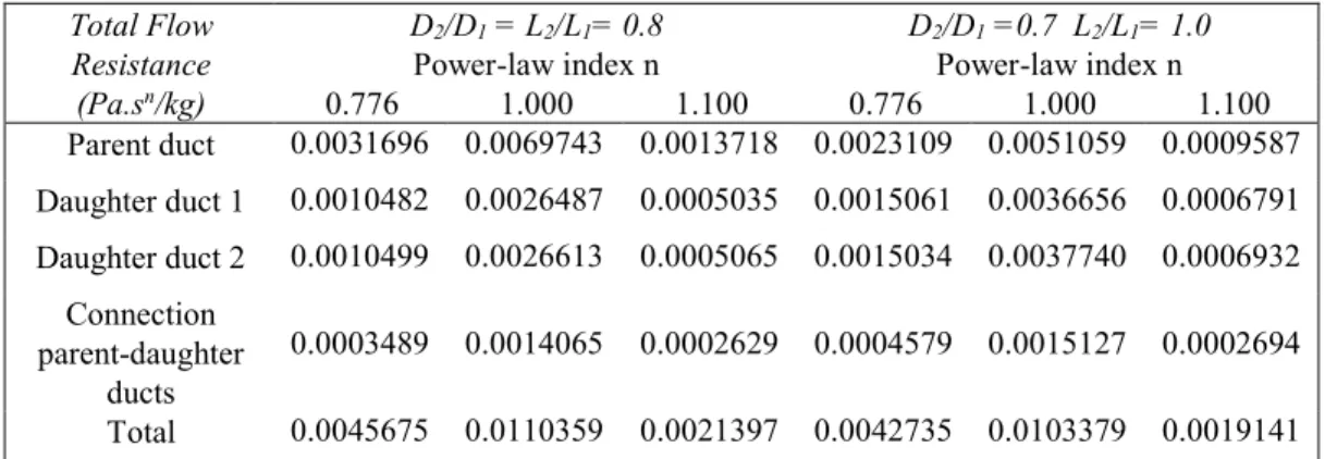
Table 2. Flow resistance per length for T-shaped assembly of ducts
Total Flow Resistance
(Pa.sn/kg)
D2/D1 = L2/L1= 0.8 D2/D1 =0.7 L2/L1= 1.0
Power-law index n Power-law index n
0.776 1.000 1.100 0.776 1.000 1.100 Parent duct 0.0031696 0.0069743 0.0013718 0.0023109 0.0051059 0.0009587 Daughter duct 1 0.0010482 0.0026487 0.0005035 0.0015061 0.0036656 0.0006791 Daughter duct 2 0.0010499 0.0026613 0.0005065 0.0015034 0.0037740 0.0006932 Connection parent-daughter ducts 0.0003489 0.0014065 0.0002629 0.0004579 0.0015127 0.0002694 Total 0.0045675 0.0110359 0.0021397 0.0042735 0.0103379 0.0019141
Notice that, analytical approaches developed by Revellin et al. [14] and Miguel [5] consider that the losses on the connection of large and small vessels together are negligible compared with friction losses through the vessels. Besides, they also assume a homogeneous flow distribution occurring in symmetric branched structures. According to Table 2, it is remarkable to notice that, the resistance in each daughter duct is not the same. This is a direct consequence of heterogeneous flow distribution in the branched structure. Besides, the flow resistance at the connection between parent and daughter ducts is not negligible as compared to the resistances of parent and daughter tubes. Higher resistance occurs for Newtonian fluids, and lower resistances for shear-thickening fluids. Although, they are of the same order of magnitude, the total resistance of T-assembly of D2/D1 =0.7 and
L2/L1= 1.0 ducts is slightly lower than the T-assembly of D2/D1 =L2/L1= 0.8 ducts
but the resistance of daughter ducts is higher. This is an interesting result and deserves a further analysis.
To explain these results, it is quite intuitive to consider the fluid flow like the flow of electric charges (electric current). For any system (fluid or electric charges), the total flowrate must be the same (principle of continuity). In our flow system, parent duct and the duct that connects parent-daughter ducts are resistors connected in series, and the daughter ducts are resistors connected in parallel. The total equivalent resistance of the resistors is
d1 d2 t p c d1 d2 R R R ~R R R R (13)
where R is the resistance and the subscripts t, p, c, d1 and d2 mean total equivalent, parent duct, connection parent-daughter ducts, d1 daughter duct 1 and d2 daughter duct 2, respectively. Eq. 13 reproduces rather well the numerical values depicted in Table 2. Notice that Rd1 and Rd2 are much lower than 1
Pa.sn/kg. Examination values depicted in Table 1 and Eq. 13, suggests that the
resistance of daughter ducts play a critical role on total equivalent resistance. A small increase of the resistance of daughter ducts causes a decrease of the total
equivalent resistance of the flow system. 4. Conclusions
From the findings presented in this study, the following main conclusions can be drawn
i) The flow is strongly dependent on the power-law index. ii) Asymmetric flow occurs in symmetric T-branched structures. iii) Different flow resistances occur in each daughter duct.
iv) Losses on the connection of large and small vessels together are not negligible.
v) Optimal branching sizes for T-shaped assemblies of ducts obtained in this numerical study do not agree completely with the results obtained with analytical models.
Acknowledgements
L.A.O. Rocha work is supported by CNPq, Brasília, DF, Brazil. A.F. Miguel acknowledge the funding provided by ICT, under contract with FCT (the Portuguese Science and Technology Foundation), Pest/OE/CTE/UI0078/2014. References
[1] Bejan, A., Shape and Structure, from Engineering to Nature, Cambridge University Press Cambridge, 2000
[2] Bejan, A., Lorente, S., Design with Constructal Theory, Wiley, New Jersey, 2008.
[3] Bejan, A., Evolution in thermodynamics, Applied Physics Reviews 4, 011305, 2017.
[4] Miguel, A. F., Penetration of inhaled aerosols in the bronchial tree. Medical Engineering and Physics 44, 25-31, 2017
[5] Miguel, A. F., Toward an optimal design principle in symmetric and asymmetric tree flow networks, Journal of Theoretical Biology 389, 101-109, 2016
[6] Miguel, A. F., Fluid flow in a porous tree-shaped network: Optimal design and extension of Hess–Murray’s law, Physica A, 423, 61-71, 2015
[7] Miguel, A. F., Quantitative unifying theory of natural design of flow systems: emergence and evolution, in: Constructal Law and the Unifying Principle of Design, Springer, 21-38, 2013
[8] Hess, W.R., Über die periphere Regulierung der Blutzirkulation, Pflüger’s Archiv für die Gesamte Physiologie des Menschen und der Tiere 168, 439–490, 1917.
angle of branching of arteries, J. Gen. Physiol. 9, 835–841, 1926.
[10] Pepe, V.R., Rocha, L.A.O., Miguel, A. F., Optimal branching structure of fluidic networks with permeable walls, BioMed Research International 2017, 5284816, 2017
[11] Uylings, H.B.M., Optimization of diameters and bifurcation angles in lung and vascular tree structures, Bull. Math. Biol. 39, 509-520, 1977
[12] Bejan, A., Rocha, L. A. O. , Lorente, S., Thermodynamic optimization of geometry: T and Y-shaped constructs of fluid streams, Int. J. Therm. Sci. 39, 949– 960, 2000.
[13] Miguel, A. F., Scaling laws and thermodynamic analysis for vascular branching of microvessels, International Journal of Fluid Mechanics Research 43, 390-403, 2016
[14] Revellin, R., Rousset, F., Baud, D., Bonjour, J., Extension of Murray's law using a non-Newtonian model of blood flow, Theor. Biol. Med. Model. 6, 7, 2009 [15] Fåhræus, R., Lindqvist, T., The viscosity of the blood in narrow capillary tubes, Am. J. Physiol. 96, 562-568, 1931
[16] Miguel, A. F., A study of entropy generation in tree-shaped flow structures, International Journal of Heat and Mass Transfer 92, 349-359, 2016
[17] Andrade Jr., J.S., Alencar, A. M., Almeida, M. P., Mendes Filho, J., Buldyrev, S. V., Zapperi, S., Stanley, H. E., Suki, B., Asymmetric flow in symmetric branched structures, Phys. Rev. Let. 81, 926, 1998