R
AQUEL DOSS
ANTOSF
ORTUNATOT
RANSPORT
M
ECHANISMS IN
I
ONIC
L
IQUID
M
EMBRANES AND THE
S
TUDY OF
T
HIOMERSAL
B
IODEGRADATION
L
ISBOAR
AQUEL DOSS
ANTOSF
ORTUNATOT
RANSPORT
M
ECHANISMS IN
I
ONIC
L
IQUID
M
EMBRANES AND THE
S
TUDY OF
T
HIOMERSAL
B
IODEGRADATION
Dissertação apresentada para obtenção do Grau de Doutor em Engenharia Química, especialidade de Engenharia Bioquímica
pela Universidade Nova de Lisboa, Faculdade de Ciências e Tecnologia.
L
ISBOA“The object of this expedition is to see
if we can find any traces of last year’s expedition.”
A
GRADECIMENTOSGostaria de começar por agradecer ao orientadores deste trabalho, Professor Doutor João Paulo Goulão Crespo e Professora Doutora Maria Ascensão Reis, todo o seu empenhamento, apoio e disponibilidade. O seu sentido crítico, exigência e franqueza, bem como a amizade demonstrada, foram decisivos para a realização deste trabalho e constituem um exemplo na maneira de trabalhar que me acompanhará no futuro.
Gostaria também de agradecer à Professora Doutora Isabel Coelhoso, com quem tive a oportunidade de trabalhar no Âmbito da Acção Integrada Luso-Espanhola, pelo seu apoio, amizade e enriquecedoras sugestões.
Gostaria de agradecer ao Professor Doutor Carlos Afonso a preparação dos líquidos iónicos e as enriquecedoras discussões. Agradeço ainda ao Dr. Luís Branco e ao Dr. Nuno Mateus (“os meus fornecedores”) a preparação dos líquidos iónicos e a simpatia e disponibilidade com que sempre me receberam “lá em baixo”.
Gostaria também de agradecer à Doutora Irene Wagner-Döbler o facto de me ter recebido no GBF – Gesellschaft für Biotechnologishe Forschung – onde tive
oportunidade de aprender as técnicas de manipulação e crescimento da estirpe utilizada neste trabalho. À Dr. Wanda Fehr agradeço todo o apoio que me dispensou durante esta estadia. Gostaria ainda de agradecer à Smith-Kline Beecham o fornecimento do efluente de produção de vacinas utilizado neste trabalho.
Agradeço à Professora Doutora Juana Benavente, do Departamento de Física Aplicada da Universidade de Málaga, a oportunidade de realizar os ensaios de espectroscopia de foto electrões de raios-X e de espectroscopia de impedância, bem como a simpatia com que me recebeu e todo o apoio demonstrado.
Agradeço à Doutora Maria Jesus González-Muñoz e à Dr. Monika Kubasiewicz a sua colaboração numa parte dos ensaios de extracção e transporte de aminoácidos e ésteres de aminoácidos.
disponibilização do viscosímetro (para amostras de alta viscosidade) e à Professora Doutora Susana Barreiros, e aos elementos do seu grupo, a disponibilização do titulador de Karl-Fisher.
Gostaria de agradecer ao Engenheiro Mário Eusébio o auxílio com o sistema de aquisição de dados e à Dr. Carla Rodrigues todo o apoio nas análises de ICP, bem como o interesse e a amizade demonstrados ao longo destes anos. Gostaria também de agradecer à D. Maria José e à D. Joaquina a sua simpatia e disponibilidade. À Katie agradeço o esforço na revisão editorial.
A todos os colegas de laboratório, passados e presentes, gostaria de agradecer o óptimo ambiente de trabalho, a boa disposição, o interesse e espírito de entreajuda, que também ajudaram a tornar estes anos inesquecíveis. Em particular gostaria de agradecer à Gundula, à Luísa, ao Paulo, às Margaridas (C, S e T) e ao Zarko todo o apoio e amizade, à Cármen e ao Pavel, aos “novatos” Zé Luís e Cristina. Agradeço à Carla Portugal, ao Vítor e ao Rui a “paciência” de me ouvirem, a ajuda e a amizade ao longo destes anos e os bons tempos passados nos congressos.
Agradeço o apoio financeiro da Fundação para a Ciência e a Tecnologia através da bolsa de doutoramento PRAXIS XXI/BD/21618/99 e da Comissão Europeia (projecto QLK3-1999-01213).
Gostaria ainda de agradecer aos amigos de sempre, Miguel, Patrícia, Joana, João, Susana, António, Nela, Rita e Cristina, bem como aos meus sogros, à Raquel e ao Kiko o apoio, a amizade e o interesse.
Aos meus pais e à Sara queria agradecer todo o apoio, incentivo e ânimo que tão necessários foram. Também agradeço a paciência com que me deixaram “monopolizar” tantas vezes a conversa do jantar com descrições exaustivas do trabalho do dia.
S
UMÁRIOO objectivo inicial deste trabalho consistiu no desenvolvimento de um bioreactor selectivo de membrana para o tratamento de efluentes industriais contaminados com um composto orgânico de mercúrio com um elevado grau de toxicidade – o tiomersal. Este trabalho focar-se-ia em dois aspectos principais: 1) desenvolvimento de uma membrana líquida suportada com líquidos iónicos, estável, para o transporte selectivo do tiomersal do efluente para um compartimento biológico, 2) estudo da cinética de biodegradação do tiomersal por uma cultura pura de Pseudomonas putida.
Assim, começou-se por determinar as propriedades físico-químicas dos líquidos iónicos utilizados e por avaliar a estabilidade operacional da membrana líquida suportada. Os resultados obtidos mostraram que, embora se obtivesse uma membrana líquida suportada com uma elevada estabilidade operacional, a água tinha uma solubilidade não negligenciável nos líquidos iónicos estudados. Identificou-se a formação de microagregados de água dentro do líquido iónico, tendo-se verificado que estes regulavam o transporte de água e pequenos iões. Em termos práticos, este comportamento significava que embora fosse possível transportar tiomersal do efluente para o compartimento biológico, este transporte poderia não ser selectivo e não era possível garantir o isolamento completo da cultura microbiana. Consequentemente, decidiu-se não operar o sistema integrado inicialmente pensado, mas apenas o sistema biológico, de forma independente. Paralelamente, procurou-se compreender os mecanismos envolvidos na solubilização e no transporte de água em membranas líquidas suportadas com líquidos iónicos e o seu efeito nos mecanismos de transporte de outros solutos solúveis em água e no desempenho da membrana líquida suportada.
permitido concluir que não havia perda significativa de fase orgânica dos poros da membrana, a formação de microagregados de água dentro do líquido iónico, constituindo um ambiente novo e não selectivo para o transporte de solutos, conduziram a uma clara deterioração da selectividade e desempenho da membrana. Não obstante, estudos de caracterização eléctrica por espectroscopia de impedância de membranas líquidas suportadas com líquidos iónicos, mostraram que a formação de microagregados de água não parece ter um efeito prejudicial nas características eléctricas das mesmas e sugerem que pode existir algum potencial para a utilização deste tipo de membranas em aplicações electroquímicas com requisitos baixos em termos de resistência.
Na segunda parte do trabalho estudou-se, em reactores descontínuos, a cinética de degradação do tiomersal por uma cultura pura de P. putida usando um efluente
S
UMMARYThe initial goal of this work was the development of a supported liquid membrane (SLM) bioreactor for the remediation of vaccine production effluents contaminated with a highly toxic organomercurial – thiomersal. Therefore, two main aspects were focused on: 1) the development of a stable supported liquid membrane – using room temperature ionic liquids (RTILs) – for the selective transport of thiomersal from the wastewater to a biological compartment, 2) study of the biodegradation kinetics of thiomersal to metallic mercury by a Pseudomonas putida strain.
The first part of the work focused on the evaluation of the physicochemical properties of ionic liquids and on the SLMs’ operational stability. The results obtained showed that, although it is possible to obtain a SLM with a high stability, water possesses non-negligible solubility in the RTILs studied. The formation of water clusters inside the hydrophobic ionic liquid was identified and found to regulate the transport of water and small ions. In practical terms, this meant that, although it was possible to transport thiomersal from the vaccine effluent to the biological compartment, complete isolation of the microbial culture could not be guaranteed and the membrane might ultimately be permeable to other species present in the aqueous vaccine wastewater. It was therefore decided not to operate the initially targeted integrated system but, instead, the biological system by itself. Additionally, attention was given to the development of a thorough understanding of the transport mechanisms involved in the solubilisation and transport of water through supported liquid membranes with RTILs as well as to the evaluation of the effect of water uptake by the SLM in the transport mechanisms of water-soluble solutes and its effect on SLM performance.
performed showed that there were no significant losses of organic phase from the membrane pores, the formation of water clusters inside the ionic liquid, which constitute new, non-selective environments for solute transport, leads to a clear deterioration of SLM performance and selectivity. Nevertheless, electrical impedance spectroscopy characterisation of the SLMs showed that the formation of water clusters did not seem to have a detrimental effect on the SLMs’ electrical characteristics and highlighted the potential of using this type of membranes in electrochemical applications with low resistance requirements.
The second part of the work studied the kinetics of thiomersal degradation by a pure culture of P. putida spi3 strain, in batch culture and using a synthetic wastewater. A
L
ISTA
BBREVIATIONS ANDN
OTATIONSABBREVIATIONS
A+ acidic form of A A- basic form of A A+/- zwitterionic form of A
A2- dianionic form of thymol blue BF4- tetrafluoroborate anion
BLM Bulk Liquid Membrane CFU Colony Forming Units
[CnMIM]+ 1-n-alkyl-3-methylimidazolium cation
[C4MIM]PF6 1-n-butyl-3-methylimidazolium hexafluorophosphate [C8MIM]PF6 1-n-octyl-3-methylimidazolium hexafluorophosphate
[C10MIM]PF6 1-n-decyl-3-methylimidazolium hexafluorophosphate [C4MIM]BF4 1-n-butyl-3-methylimidazolium tetrafluoroborate
[C10MIM]BF4 1-n-decyl-3-methylimidazolium tetrafluoroborate
CSTR Continuous Stirred Tank Reactor D Dilution Rate
DO Dissolved Oxygen
e-phe (L) - phenylalanine methyl ester (protonated form) e-phg (S)-(+)-2-phenylglycine methyl ester (protonated form) e-pro (L) - proline benzyl ester (protonated form)
H2A zwitterionic form of thymol blue HA- monoanionic form of thymol blue
HPLC High Performance Liquid Chromatography ICP Inductive Coupled Plasma Spectroanalysis IL Ionic Liquid
IR Refractive Index ISA Ionic Strength Adjuster
NMR Nuclear Magnetic Resonance Spectroscopy OD Optical Density
OUR Oxygen Uptake Rate PF6- hexafluorophosphate anion Phe (L) – phenylalanine
Phg (L) – phenylglycine PVDF polyvinylidene fluoride RC resistance-capacitor R – SH Sulphydryl group
RTIL Room Temperature Ionic Liquid SLM Supported Liquid Membrane
SLM_H SLM with the PVDF hydrophobic support SLMU SLM after operation (used)
T2O Tritiated water Trp (L) - tryptophan UV Ultraviolet VIS Visible
XPS X-ray photoelectron spectroscopy
% saturation ratio between the water concentration and the water solubility limit
VARIABLES AND NOTATIONS
Am membrane area (cm2)
C solute concentration (mol/l)
C capacitance (F) [Chapter 5]
D dilution rate (h-1)
D diffusion coefficient (cm2/s)
Deff effective diffusion coefficient (cm2/s)
D0(A/B) diffusion coefficient of solute A in solvent B at infinite dilution (cm2/s)
F glucose glucose inflow rate (mgl-1h-1) F NH4 ammonia inflow rate (mg Nl-1h-1)
F thiomersal thiomersal inflow rate (mgl-1h-1) [glucose]in glucose inlet concentration (g/l)
Hgin mercury inflow rate (mg Hg l-1h-1) Hgout mercury outflow rate (mg Hg l-1h-1)
i electric current (A)
I0 maximum current intensity (A)
J flux (mol cm-2s-1)
k Boltzmann constant (J K-1)
K overall mass transfer coefficient (cm/s)
l membrane thickness (cm)
[NH4]in ammonia inlet concentration (mg N/l)
OURv volumetric oxygen uptake rate (mg O2 l-1min-1)
OURsp specific oxygen uptake rate (mgO2/gcell.min)
P partition coefficient (dimensionless)
R resistance (Ω)
Re Reynolds number (dimensionless)
r glucose glucose consumption rate (mgl-1h-1) r thiomersal thiomersal degradation rate (mgl-1h-1)
r thiomersal sp specific thiomersal degradation rate (mgh-1gcell-1)
rp pore size (µm)
[s] mmol/l
[thiomersal]in thiomersal inlet concentration (mg/l)
t time (s)
T temperature (K)
to lag phase time (s)
V volume (l)
V0 maximum voltage intensity (V) X biomass concentration (g/l)
YO2/S observed oxygen substrate yield (gO2/gs) Yx/s observed growth yield in glucose (gx/gs)
GREEK SYMBOLS
ε membrane porosity (dimensionless) η viscosity (mPas)
µ specific growth rate (h-1)
µmax maximum specific growth rate (h-1)
v voltage applied (V)
ρ resistivity (Ωcm) σ conductivity (Scm-1)
τ membrane tortuosity (dimensionless)
φ phase angle between the applied voltage and the current intensity (rad) ϖ angular frequency (Hz)
SUBSCRIPTS
0 initial conditions
aq aqueous phase
e electrolyte solution
f feed phase
IL ionic liquid phase
img imaginary
ms membrane system
real real
s stripping phase
T
ABLE OFC
ONTENTS1.INTRODUCTION
1.1. BACKGROUND 3
1.2. INITIAL RESEARCH OBJECTIVES 7
1.3. RESEARCH STRATEGY 7
1.3.1. DEVELOPMENT OF THE SUPPORTED LIQUID MEMBRANE 8
1.3.2. STUDY OF THE THIOMERSAL BIODEGRADATION PROCESS 11
1.4. STRUCTURE OF THE THESIS 12
1.5. REFERENCES 14
2.SUPPORTED IONIC LIQUID MEMBRANES:
STUDY OF STABILITY AND TRANSPORT MECHANISMS
2.1. INTRODUCTION 19
2.2. MATERIALS AND METHODS 21
2.2.1. DETERMINATION OF THE IONIC LIQUIDS PHYSICOCHEMICAL PROPERTIES 21
2.2.2. PREPARATION OF THE SUPPORTED LIQUID MEMBRANES 22
2.2.3. MEMBRANE STABILITY STUDIES 23
2.2.4. TRANSPORT STUDIES 23
2.2.4.1. Water Transport 24
2.2.4.2. Sodium Chloride Transport 25
2.2.4.3. Thymol Blue Transport 25
2.2.5. CALCULATION METHODS 26
2.3. RESULTS AND DISCUSSION 26
2.3.1. DETERMINATION OF THE PHYSICOCHEMICAL PROPERTIES OF IONIC LIQUIDS 26
2.3.2. STABILITY STUDIES 29
2.3.3. TRANSPORT STUDIES 32
2.3.3.1. Water Transport 32
2.3.3.2. Sodium Chloride Transport 39
2.3.3.3. Thymol Blue Transport 40
2.4. CONCLUSIONS 43
3.STABILITY OF SUPPORTED IONIC LIQUID MEMBRANES AS STUDIED BY X-RAY PHOTOELECTRON SPECTROSCOPY
3.1. INTRODUCTION 49
3.2. MATERIALS AND METHODS 51
3.2.1. MATERIALS 51
3.2.2. MEMBRANE STABILITY STUDIES 51
3.2.3. X-RAY PHOTOELECTRON SPECTROSCOPY (XPS)MEASUREMENTS 52
3.3. RESULTS AND DISCUSSION 53
3.3.1. MEMBRANE STABILITY STUDIES 53
3.3.2. X-RAY PHOTOELECTRON SPECTROSCOPY (XPS)MEASUREMENTS 55
3.4. CONCLUSIONS 60
3.5. REFERENCES 61
4.IONIC LIQUID MEMBRANES:
THE INFLUENCE OF WATER ON SOLUTE TRANSPORT
4.1. INTRODUCTION 67
4.2. MATERIALS AND METHODS 69
4.2.1. MATERIALS 69
4.2.2. EXTRACTION STUDIES 70
4.2.3. TRANSPORT STUDIES 70
4.2.3.1. Supported Liquid Membrane preparation 71
4.2.3.2. Supported Liquid Membrane configuration 71
4.2.3.3. Bulk Liquid Membrane configuration 71
4.2.4. ANALYTICAL METHODS 73
4.2.5. CALCULATION METHODS 73
4.3. RESULTS AND DISCUSSION 73
4.3.1. EXTRACTION STUDIES WITH AMINO ACIDS 73
4.3.2. EXTRACTION STUDIES WITH AMINO ACID ESTERS 75
4.3.3. TRANSPORT STUDIES IN SUPPORTED LIQUID MEMBRANE 77
4.3.4. TRANSPORT STUDIES IN BULK LIQUID MEMBRANE 83
4.4. CONCLUSIONS 86
5.ELECTROCHEMICAL CHARACTERISATION OF SUPPORTED IONIC LIQUID MEMBRANES
5.1. INTRODUCTION 93
5.2. THEORETICAL BACKGROUND 95
5.3. MATERIALS AND METHODS 96
5.3.1. MATERIALS 96
5.3.2. ELECTRICAL IMPEDANCE SPECTROSCOPY MEASUREMENTS 97
5.4. RESULTS AND DISCUSSION 98
5.4.1. IONIC LIQUIDS 98
5.4.2. SUPPORTED IONIC LIQUID MEMBRANES 103
5.4.3. VARIATION IN THE SLMS’ ELECTRICAL CHARACTERISTICS DURING OPERATION 106
5.5. CONCLUSIONS 108
5.6. REFERENCES 109
6.THIOMERSAL BIODEGRADATION BY Pseudomonas putida
6.1. INTRODUCTION 115
6.2. MATERIALS AND METHODS 118
6.2.1. BACTERIAL CULTURE 118
6.2.2. CULTURE MEDIA 119
6.2.3. REACTOR SET-UP AND OPERATION 120
6.2.3.1. Batch Reactor Operation 121
6.2.3.2. Continuous Reactor Operation 121
6.2.4. ANALYTICAL METHODS 123
6.2.4.1. Cell Density and Dry Weight Determination 123
6.2.4.2. Oxygen Uptake Rate (OUR) Determination 124
6.2.4.3. Thiomersal Analysis 125
6.2.4.4. Total Mercury Analysis 125
6.2.4.5. Glucose Analysis 125
6.2.4.6. Ammonia Analysis 126
6.2.5. CALCULATION METHODS 126
6.3. RESULTS AND DISCUSSION 127
6.3.1. BATCH REACTOR OPERATION 128
6.3.2. CONTINUOUS REACTOR OPERATION 133
6.3.2.1. Biodegradation of thiomersal in a CSTR fed with a synthetic wastewater 133 6.3.2.2. Biodegradation of thiomersal in a CSTR fed with vaccine wastewater 137
6.4. CONCLUSIONS 146
7.CONCLUSIONS
7.1. TRANSPORT MECHANISMS IN IONIC LIQUID MEMBRANES 153
7.2. STUDY OF THIOMERSAL BIODEGRADATION 156
7.3. SUGGESTIONS FOR FUTURE RESEARCH 156
7.4. REFERENCES 158
APPENDIX A.MEASUREMENT OF THE OXYGEN UPTAKE RATE 161
T
ABLE OFF
IGURESFigure 1.1 – Illustration of the Supported Liquid Membrane Bioreactor principle. 5
Figure 1.2 – Structure of the room temperature ionic liquids used in this work 6
Figure 1.3 – Evolution of the thiomersal and counter-ion (tert-butyl acetic acid) concentrations in the feed (close symbols – n) and stripping compartments (open
symbols – ¨). 10
Figure 2.1 – General synthesis reactions of the RTILs used in this work. 21
Figure 2.2 – Experimental set-up for the transport studies with supported liquid
membranes. 24
Figure 2.3 – Experimental set-up for the transport studies in bulk liquid membrane. 25
Figure 2.4 – Apparent Viscosity of [CnMIM]PF6 (n= 4, 8 and 10) and [C10MIM]BF4 as
a function of temperature. 28
Figure 2.5 – Evolution of ionic liquid [C4MIM]PF6 concentration in the two contacting aqueous compartments (open symbols and closed symbols) for the different supporting
membranes tested. 30
Figure 2.6 – Evolution of T20 concentration in the stripping phase (Cs) for the two SLM
tested. 33
Figure 2.7 – Apparent viscosity of [CnMIM]PF6 (n= 4 and 8), at 25ºC, with increasing
water concentration in the ionic liquid. 35
Figure 2.8 – Evolution of T20 concentration in the stripping phase for the two LM tested: BLM with [C4MIM]PF6, BLM with [C8MIM]PF6; and evolution of the water concentration in the ionic liquid: –? – BLM with [C4MIM]PF6, –? – BLM with
[C8MIM]PF6. 36
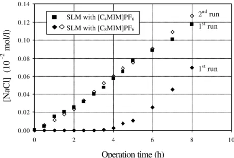
Figure 2.9 – Evolution of NaCl concentration in the stripping phase for the two SLM tested: Closed symbols – 1st run; Opens symbols – 2nd run. 39
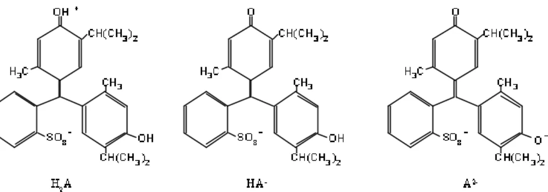
Figure 2.10 – Thymol blue forms: red form H2A, Z = 0; yellow form HA-, Z = -1 and
blue form A2-, Z = -2. 41
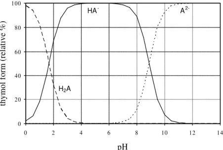
Figure 2.11 – Evolution of the relative percentage of each thymol blue form (H2A, HA
Figure 2.12 – Evolution of the concentration of each thymol blue form (H2A, HA- and A2-) in the feed phase for a liquid membrane with [C4MIM]PF6. 42
Figure 3.1 – Evolution of the ionic liquid [C8MIM]PF6 concentration in the contacting aqueous phases for the different hydrodynamic conditions used (Re1, Re2, Re3); filled symbols – contacting phase A, open symbols – contacting phase B. 54
Figure 3.2 – C1s core level spectra, obtained by X-ray photoelectron spectroscopy, for the ionic liquids [C4MIM]PF6, [C8MIM]PF6 and [C10MIM]BF4 and for the PVDF
supporting membrane. 57
Figure 3.3 – C1s core level spectra obtained by X-ray photoelectron spectroscopy for the ionic liquid [C8MIM]PF6, the PVDF supporting membrane and the SLM with [C8MIM]PF6 immediately after preparation (SLM) and after one week in de-ionised
water (SLMU). 60
Figure 4.1 – Experimental set-up for the transport studies in bulk liquid membrane. 72
Figure 4.2 – Molecular Structure of proline benzyl ester (e-pro), phenylalanine methyl ester (e-phe) and phenylglycine methyl ester (e-phg). 75
Figure 4.3 – Equilibrium concentrations of proline benzyl ester (e-pro), phenylalanine methyl ester (e-phe) and phenylglycine methyl ester (e-phg) in the organic phase (CIL*) versus their equilibrium concentration in the aqueous phase (Ca*). 76
Figure 4.4 – Evolution of solute (e-pro, e-phe, e-phg, phe) concentration in the feed ([solute]f] and stripping ([solute]s) phases in supported liquid membranes. 77
Figure 4.5 – Evolution of phenylalanine concentration in the stripping phase of a
supported liquid membrane; closed symbols – 1st run, open symbols – 2nd run. 79
Figure 4.6 – Evolution of solute (e-pro, e-phe and e-phg) concentration in the stripping phase of a supported liquid membrane – 1st run. 80
Figure 4.7 – Evolution of solute (e-pro, e-phe and e-phg) concentration in the stripping phase of a supported liquid membrane – 2nd run. 81
Figure 4.8 – Evolution of proline benzyl ester (e-pro) concentration in the feed (¨), stripping (n) and ionic liquid (-×-) phases, and evolution of the water concentration inside the ionic liquid (-∆-), expressed as % saturation, in bulk liquid membrane. 83
Figure 4.9 – Evolution of phenylglycine methyl ester (e-phg) concentration in the feed (¨), stripping (n) and ionic liquid (-×-) phases, and evolution of the water concentration inside the ionic liquid (-∆-), expressed as % saturation, in bulk liquid membrane. 84
Figure 5.1 – Nyquist plot of the ionic liquids [CnMIM]PF6(n = 4, 8) and [C10MIM]BF4. 98 Figure 5.2 – Resistance values of the ionic liquids [CnMIM]PF6(n = 4, 8) and
[C10MIM]BF4 as a function of the % of water saturation inside the ionic liquid. 100
Figure 5.4 – Nyquist plotof the hydrophilic PVDF supporting membrane, the supported liquid membranes (SLMs) with [CnMIM]PF6 (n = 4 and 8) and [C10MIM]BF4, the hydrophobic PVDF supporting membrane, the supported liquid membrane with
[C8MIM]PF6 (SLM_H) and the Nafion 117 membrane. 103
Figure 5.5 – Evolution of the SLMs’ resistance during operation. 107
Figure 6.1 – Mechanism for thiomersal biodegradation. 118
Figure 6.2 – Bioreactor set-up. 122
Figure 6.3 – Evolution of the cell dry weight, glucose and thiomersal concentrations and of the specific oxygen uptake rate (OURsp) in a batch culture of P. putida spi3
(experiment A). 128
Figure 6.4 - Evolution of the cell dry weight and glucose concentrations and of the specific oxygen uptake rate (OURsp) in a batch culture of P. putida spi 3, in the absence
of thiomersal (experiment B). 129
Figure 6.5 – Evolution of the thiomersal concentration in the growth medium in the
absence of microorganisms. 130
Figure 6.6 – Evolution of the cell dry weight, glucose and thiomersal concentrations in a continuous culture of P. putida spi3 fed with a synthetic wastewater. 133
Figure 6.7 – Evolution of the thiomersal concentration, after the thiomersal pulses, in a continuous culture of P. putida spi3 fed with a synthetic wastewater. 135
Figure 6.8 – Variation in thiomersal degradation rate with the thiomersal concentration. 136 Figure 6.9 – Evolution of cell dry weight, total mercury, glucose and ammonia
concentrations in a continuous culture of P. putida spi3 fed with vaccine wastewater
supplemented with ammonia (D = 0.03h-1). 138
Figure 6.10 – Evolution of cell dry weight, total mercury and glucose concentrations in a continuous culture of P. putida spi3 fed with vaccine wastewater (D = 0.03h-1). 138
Figure 6.11 – Evolution of cell dry weight, total mercury and glucose concentrations in a continuous culture of P. putida spi3 fed with vaccine wastewater (D = 0.022h-1). 141
Figure 6.12 – Evolution of cell dry weight, thiomersal and glucose concentrations in a continuous culture of P. putida spi3 fed with vaccine wastewater (D = 0.05 h-1). 142
Figure 6.13 – Evolution of cell dry weight, total mercury and glucose concentrations in a continuous culture of P. putida spi3 fed with vaccine wastewater (D = 0.1 h-1). 142
Figure 6.14 – Variation of residual mercury concentration at the bioreactor outlet as a
function of the dilution rate. 144
Figure A.1 – Variation of the dissolved oxygen concentration in the respirometer with
T
ABLE OFT
ABLESTable 2.1 – Physicochemical Properties of the RTILs studied. 27
Table 2.2 – Evaluation of the membranes hydrophilic (•)/ hydrophobic (⊗) character. 31
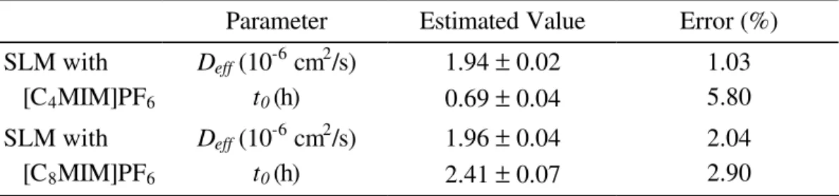
Table 2.3 – Deff and t0 for T2O obtained from the experimental data, using Equation
(2.2). 34
Table 2.4 – Experimental and estimated effective diffusion coefficients (Deff) for T2O.38
Table 3.1 – Surface composition by XPS analysis of the PVDF supporting membrane and of the ionic liquids [C4MIM]PF6, [C8MIM]PF6 and [C10MIM]BF4 (theoretical ratios
between brackets). 56
Table 3.2 – Surface composition by XPS analysis of the SLMs with the ionic liquids [C4MIM]PF6, [C8MIM]PF6 and [C10MIM]BF4, immediately after preparation (SLM) and after one week in de-ionised water (SLMU) (theoretical ratios between brackets). 58
Table 4.1 – Ionization constants and molecular structure of the different forms of
tryptophan, phenylalanine and phenylglycine [16-17]. 74
Table 4.2 – Global mass transfer coefficients (K) for the different solutes tested,
obtained from the experimental data, using Equations (4.2) and (4.3). 78
Table 4.3 – Global mass transfer coefficients (K) for the different solutes tested,
obtained from the experimental data, using Equation (4.2) (1st run- first 3 hours) 82
Table 4.4 – Global mass transfer coefficients (K) for the two solutes tested, obtained from the experimental data in bulk liquid membrane. 86
Table 5.1 – Resistance and Capacitance values obtained for the ionic liquids
[C4MIM]PF6, [C8MIM]PF6 and [C10MIM]BF4. 99
Table 5.2 – Membrane system electrical resistance and capacitance values obtained for the PVDF supporting membranes, the SLMs with [CnMIM]PF6 (n = 4,8) and
[C10MIM]BF4 and the SLM obtained by immobilizing [C8MIM]PF6 in the PVDF
hydrophobic support (SLM_H). 104
Table 6.1 – Operation conditions for the continuous bioreactor fed with vaccine
production effluent. 123
Table 6.2 – Kinetic and stoichiometric parameters for a P. putida spi3 grown in the
Table 6.3 – Steady state biomass and glucose concentrations, thiomersal consumption rates (volumetric and specific), total mercury residual concentration and % of mercury removal in a CSTR fed with a vaccine production wastewater, at D = 0.03h-1, with and
without external ammonia addition. 140
Table 6.4 – Steady state biomass and glucose concentrations, thiomersal consumption rates (volumetric and specific), total mercury residual concentration and % of mercury removal in a CSTR fed with a vaccine production wastewater for D = 0.022, 0.05 and
0.1 h-1. 143
C
HAPTER
1
_______________________________________________
I
NTRODUCTION
1.1. BACKGROUND 3
1.2. INITIAL RESEARCH OBJECTIVES 7
1.3. RESEARCH STRATEGY 7
1.3.1. DEVELOPMENT OF THE SUPPORTED LIQUID MEMBRANE 8
1.3.2. STUDY OF THE THIOMERSAL BIODEGRADATION PROCESS 11
1.4. STRUCTURE OF THE THES IS 12
1.INTRODUCTION
1.1. Background
Sodium 2-ethylmercuriothio-benzoate (also known as thiomersal, thimerosal or mercurothiolate) is a toxic organomercurial with a strong bactericide effect that has been used routinely as an additive to biological products and cosmetics since the 1930’s. Some of the many products containing thiomersal include nasal preparations (e.g. Neo-Synephrine), antibiotics for the eyes (e.g. Cortisporin), cosmetics (e.g.
L’Oreal Miracle Mask) and vaccines (e.g. Recombivax HB, Engerix B).
Thiomersal is the most widely used antimicrobial preservative in vaccine production in order to prevent bacterial growth in the cell culture and media and to maintain a sterile production line [1]. Thiomersal is also extensively used to prevent bacterial and fungal growth in the vaccine’s final containers during storage, especially in the case of multi-dose vials. In addition to its antimicrobial activity, thiomersal also performs other functions affecting the vaccines’ antigenicity and stability.
When used to prevent contamination in multi-dose vials (e.g. vaccines against diphtheria, tetanus, pertussis or hepatitis B) thiomersal can be added in concentrations varying from 10 to 50 µg per dose. Other vaccines may contain trace amounts of thiomersal (less than 0.5 µg per dose) if thiomersal is only used during the production process.
Thiomersal contains 49.6% of mercury by weight and is metabolised in the human body to ethyl mercury and thiosalycilic acid. The ethylmercury is mainly excreted as inorganic mercury in the faeces [2, 3]. Although there is no conclusive evidence of mercury toxicity in newborns, children or adults exposed to thiomersal in vaccines [4, 5], significant pressure is being exerted on vaccine manufacturers, especially in the USA, to remove thiomersal from vaccine production. Some national public health authorities are promoting the replacement of those vaccines containing thiomersal with those without as a precautionary measure [6].
limited and insufficient to meet global needs. Therefore, the World Health Organization and the Global Advisory Committee on Vaccine Safety state that, at this point, there is no reason to change current immunisation practices with thiomersal containing vaccines on the grounds of safety [7] and thiomersal continues to be used in many vaccine production processes.
As a result, the wastewaters resulting from those vaccine production processes are highly polluted not only with a thiomersal concentration ranging from 25 mg/l to 50 mg/l (well above the European limit for mercury effluents discharges of 0.05 mg Hg /l ⇔ 0.1 mg/l thiomersal) [8] but also with a complex mix of additives and by-products. Since there is presently no remediation technology available for organomercurials, in most cases the wastewater is delivered to municipal waste treatment plants. The high mercury content in the dried activated sludge at the treatments plants outlet prevents its use in agriculture, and incineration is the only option for disposal. Consequently, thiomersal containing wastewaters represent a burden to the environment and require costly and energy intensive treatments.
In an attempt to address this problem, this work proposed a new biotechnological process based on the selective extraction of thiomersal through a supported liquid membrane (SLM) from the wastewater to a biological compartment where it would be transformed into the metallic form by a mercury resistant microbial strain. The metallic mercury produced might then be stripped from the system by aeration, concentrated and recovered in pure form.
In this way, the microbial culture could be completely confined and protected from the potentially aggressive environment of the vaccine effluent, unlike what happens in conventional biological processes. In the biological compartment, the degradation of thiomersal would continuo usly provide the driving force for its transport across the membrane. To enhance transport and maintain electroneutrality in both circuits, the
and, as a result, to control independently the mercury residual concentration in the treated effluent to guarantee that it was within the legal limits (< 0.05 mg Hg /l).
In the proposed process, the reactor is divided in two individual compartments: a wastewater compartment and a biological one, separated by a membrane selective for the target pollutant. This type of concept has been successfully studied and applied in recent years for a large number of pollutants [9-15].
The utilisation of an adequate membrane, selective for the target pollutant and essentially impermeable to all other ionic species present in the wastewater and biological compartments, is essential to assure a good performance of the membrane bioreactor. Moreover, the membrane must exhibit high operational stability when exposed to the wastewater stream for long periods. At the beginning of the project, it was thought that all these conditions could be met by using supported liquid membranes prepared by immobilising a room temperature ionic liquid (RTIL) in a porous supporting membrane.
The operating principle of the proposed Supported Liquid Membrane Bioreactor is depicted in Figure 1.1.
Biological degradation t o Hg0
Vaccine Effluent Wastewater compartment Biological compartment Thiomersal Thiomersal Supporting Membrane Supporting Membrane
I onic Liquid
Supported Liquid Membrane
Counter -ion Counter-ion Biological degradationt o Hg0
Vaccine Effluent Wastewater compartment Biological compartment Thiomersal Thiomersal Supporting Membrane Supporting Membrane
I onic Liquid
Supported Liquid Membrane
Counter -ion Counter-ion
Figure 1.1 – Illustration of the Supported Liquid Membrane Bioreactor principle.
The Pseudomonas putida spi3 strain used in this work was isolated from sediments of
as broad-spectrum mercury resistant and preliminary experiments carried out in GBF showed that the isolated strain was able to transform thiomersal in the less toxic Hg0 form [16].
The room temperature ionic liquids (RTILs) immobilised in the porous supporting membrane, are thermally stable salts, liquid at room temperature, composed of an organic cation and either an organic or an inorganic anion.
Although there are reports on the use of room-temperature molten salts for electrochemical applications in the late 1970s [17-19], room temperature ionic liquids remained relatively unexplored until the late 90s. From then on, however, RTILs, especially those based upon the 1-n-alkyl-3-methylimidazolium cation ([CnMIM]+), have been the object of growing research interest [20-23]. Because they are air and water stable, have a non-measurable vapour pressure and are able to solvate a variety of organic and inorganic species ionic liquids are emerging as alternative green solvents, namely as reaction media for synthesis, catalysis and biocatalysis [24-26].
The fact that ionic liquids are air and water stable, non-volatile and, depending on the anion, immiscible with water made their use very appealing in the attempt to obtain stable supported liquid membranes [27,28]. Additionally, the hydrophobic character of some ionic liquids creates a suitable environment for diffusion of molecules with a polar moiety but also with significant hydrophobic regions like thiomersal.
The structure of the room temperature ionic liquids used in this work, based on the 1-n
-alkyl-3-methylimidazolium cation bounded to an inorganic anion is presented in Figure 1.2. The anions used were hexafluorophosphate – PF6- and tetrafluoroborate – BF4-.
At the beginning of the project, the use of ionic liquids in supported liquid membranes seemed very promising as their properties suggested it was possible to introduce them in the porous structure of the supporting membrane and obtain a stable supported liquid membrane, without risk of liquid displacement by evaporation or by dissolution in the aqueous phase. Their hydrophobic character and low affinity to ionic species such as sodium and chloride [29] suggested that they might be good candidates for the selective transport of thiomersal from the feed wastewater to the biological compartment and, at the same time, constitute a barrier to the transport of other ionic species present in the wastewater and the biological medium.
1.2. Initial Research Objectives
At the beginning of this research project and simultaneous with the beginning of the mentioned European Project, it was our purpose to develop a selective membrane bioreactor for the biodegradation of thiomersal. The two main factors governing the operation of the supported liquid membrane bioreactor are the thiomersal mass transfer through the SLM and the biodegradation of thiomersal in the biological compartment. In this context, the main objectives defined, both for the PhD project and the European project were:
1) the development of a stable supported ionic liquid membrane, able to transport selectively thiomersal from the wastewater to the biological compartment;
2) the identification of the optimal mass transfer conditions for thiomersal transport trough the supported ionic liquid membrane ;
3) the study and optimisation of the thiomersal biodegradation process in a contaminated synthetic wastewater by the Pseudomonas putida spi3 strain; and
4) the integration of the transport system and the biodegradation process and set-up of an integrated transport/biodegradation system able to deal with real effluent streams containing thiomersal.
1.3. Research Strategy
the integration of the two components above in order to develop a transport/biodegradation system. For reasons to be outlined below, this research strategy had to be adjusted during the course of the project.
1.3.1. Development of the supported liquid membrane
The membrane system was based on the use of novel solvents, room temperature ionic liquids, and on their immobilisation in a porous supporting membrane in order to obtain a stable and selective SLM.
The initial phase required the selection of the supporting membrane and of the ionic liquid to be used as organic phase in the SLM. The ionic liquids used were synthesised by the group of Professor Carlos Afonso (Centro Química Física Molecular, IST/UTL,
Portugal) and were chosen due to their immiscibility with water. Several commercial porous membranes of different materials were selected as supporting membranes. The selection of the best combination ionic liquid/supporting membrane, in terms of both SLM stability and selectivity for thiomersal transport, was therefore the first step in this research project.
Following this line of work, the determination of the physicochemical properties of the selected ionic liquids ([CnMIM]PF6 (n= 4, 8 and 10) and [CnMIM]BF4 (n= 4 and 10)) and the evaluation of their impact on the stability of the resulting SLM were carried out. Particular attention was given to the ionic liquids’ properties with impact on the transport flux (i.e. viscosity) and on the SLM stability (i.e. water solubility in the selected RTILs and solubility of the RTILs in water).
promising results regarding stability. Based on the measured physicochemical properties and on the results obtained in the stability studies, the system polyvinylidene fluoride (PVDF) supporting membrane/[CnMIM]PF6 (n=4,8) ionic liquid was selected for further study.
Simultaneously, the selection of an adequate counter-ion for thiomersal transport was addressed. The following factors had to be considered:
1) the counter-ion had to be non-toxic both to the environment and the microbial culture;
2) it could not be metabolised by the microbial culture; and
3) its utilisation had to significantly increase the transport rate of thiomersal through the SLM.
Carboxylic acids are non-toxic compounds with characteristics that made them potential counter-ions. Among the carboxylic acids, isobutyric acid, isovaleric acid, 2,2 dimethylbutyric acid and tert-butyl acetic acid were selected and their possible toxic effects on the microbial culture or metabolisation by the selected strain were evaluated. None of them was found to be toxic to the microbial culture in the concentration range used (10-20 mmol/l). However, isobutyric acid and isovaleric acid were metabolised by the microbial culture. Consequently, the carboxylic acids selected for the transport studies were 2,2 dimethylbutyric acid and tert-butyl acetic acid. Preliminary experiments showed no significant difference in the transport fluxes of thiomersal for either counter-ion. Since they have low environmental impact and ter-butyl acetic acid is about two times cheaper than 2,2 dimethylbutyric acid, the former was selected as the counter-ion for thiomersal transport.
0 2 4 6 8 10 12 14
0 5 10 15 20 25
Operation time (h)
0 2 4 6 8 10 12 14
0 5 10 15 20 25
Operation time (h)
[thiomersal] (10
-2 mmol/l)
[counter-ion] (mmol/l)
Figure 1.3 – Evolution of the thiomersal and counter-ion (tert-butyl acetic acid) concentrations in the feed (close symbols – n) and stripping compartments (open symbols – ¨).
As can be observed in Figure 1.3 the concentration of both solutes in each compartment after 20 hours was approximately constant and equal to half of their initial concentration, meaning that it was possible to close the individual mass balances. However, when the transport fluxes for both solutes were compared, it became obvious that the thiomersal flux was much lower than that of the counter-ion. For that reason, it was not possible to close the charge balances. The observed behaviour strongly suggested that the transport mechanism was not purely counter-ion transport and that there was another ion present in the medium simultaneously being transported (co-ion transport).
At this point and bearing in mind that water has a non-negligible solubility in the RTILs used, the above-described observations prompted us to study the potential role that water might play in the mechanism of solute transport (namely small ions) between aqueous phases, when separated by a supported ionic liquid membrane. Consequently, understanding the mechanisms involved in the solubilisation and transport of water through supported liquid membranes with RTILs and the effect of water on the transport of water-soluble ions became a central point in this research work.
The results obtained (described in chapters 2 and 4) highlighted the determinant role played by water, solubilised inside the ionic liquids, in the transport mechanism. In fact, it became clear that the transport mechanism of water and small water-soluble ions through SLMs with [CnMIM]PF6 RTILs was regulated by the dynamics of water microenvironments inside the RTIL, rather than by molecular diffusion through the bulk of the ionic liquid. This meant that, although it was possible to transport thiomersal from the vaccine effluent to the biological compartment, complete isolation of the microbial culture could not be guaranteed and the membrane might ultimately be permeable to other species present in the aqueous vaccine wastewater. It was therefore decided not to operate the initially planned integrated system, but concentrate instead on the thiomersal biodegradation process.
1.3.2. Study of the thiomersal biodegradation process
The degradation of thiomersal to metallic mercury in the biological compartment was based on the use of broad-spectrum mercury resistant bacteria, isolated from sediments of the Spittelwasser River (Germany).
In the initial phase, the kinetics of thiomersal degradation by P. putida spi3 was
evaluated in batch reactors using synthetic thiomersal contaminated wastewater. Additionally, the ability of the microbial strain to remediate such wastewater was evaluated in a continuous stirred tank reactor (CSTR).
1.4. Structure of the thesis
Due to the fact that there were no reports on the utilisation of RTILs in supported liquid membranes, between two aqueous phases, available at the beginning of the project it was not possible to anticipate many of the problems encountered. More specifically: the non-negligible solubility of water in the tested RTILs and the water uptake by the SLM, during operation time, that ultimately lead to a loss of membrane selectivity, rendering the SLM permeable to other species present in the vaccine wastewater. As a result, a redefinition of the research objectives was undertaken and this thesis was divided in two major components: the study of the transport mechanisms in liquid membranes with ionic liquids and the study of thiomersal biodegradation.
Thus, the main objectives, as re-defined, were:
1) the evaluation of the operational stability of supported ionic liquid membranes; 2) the development of a thorough understanding of the transport mechanisms
involved in the solubilisation and the transport of water through supported ionic liquid membranes;
3) the evaluation of the effect of water uptake by the SLM in the transport mechanisms of water-soluble solutes and on the SLM performance;
4) the evaluation of the potential utilisation of supported ionic liquid membranes in electrochemical applications; and
5) the evaluation of the feasibility of using a continuous stirred bioreactor for the remediation of thiomersal contaminated vaccine effluents.
The structure of the thesis generally follows the research objectives outlined above, except for point 1 (the evaluation of the SLMs’ operational stability) which is addressed in two different chapter, as was dictated by the evolution of the research.
chapter is detailed in the context of the respective theme and, when applicable, is related to that used in previous chapters.
To begin with, Chapter 2 discusses the physicochemical properties of the ionic liquids synthesised and evaluates their impact on the behaviour of the resulting supported ionic liquid membranes. In addition, the effect of the supporting membrane material on the SLM’s stability is evaluated. The understanding of the transport mechanisms involved in the transport of water through ionic liquid membranes and the effect of water mobility on the transport of small water-soluble ions are also discussed in this chapter. Following the same approach, the partitioning and transport behaviour of a larger water-soluble zwitterionic compound was also addressed.
Chapter 3 assesses the supported ionic liquid membranes’ operational stability under dynamic conditions. X-ray photoelectron spectroscopy (XPS), a technique that allows the characterisation of the surface chemical composition of a given sample, was used as a tool to gather valuable information about the SLMs integrity and stability.
Following the studies of the transport of a larger water-soluble zwitterionic solute, addressed at the end of Chapter 2, Chapter 4 provides an in-depth analysis of the role of water microenvironments in the transport of solutes through liquids membranes with RTILs.
Chapter 5 evaluates the potential of using supported ionic liquid membranes in electrochemical applications. Therefore, the electrical characterisation of SLMs with ionic liquids by impedance spectroscopy is presented and discussed. This non-invasive technique allows one to determine the electrical properties of a given sample and was used to identify the electrical characteristics of the supporting membrane, the ionic liquids and the SLMs. In order to understand the impact of the presence of water inside the RTILs on the electrical properties of the SLMs, impedance measurements of the membranes, placed between two aqueous solutions, were also carried out at regular time intervals.
investigated in batch reactors using a synthetic wastewater. Subsequently a continuous stirred tank reactor (CSTR) fed with the same synthetic wastewater was operated, and the bioreactor performance and robus tness was evaluated when exposed to thiomersal shock loads. In a second stage, for the reasons discussed above, the bioreactor was fed directly with a real vaccine wastewater contaminated with thiomersal and the cultures’ ability to grow in the effluent and remediate the wastewater was evaluated for different conditions of reactor operation.
Chapter 7 presents the overall conclusions of this research project and suggestions for further research.
1.5. References
[1] Keith L.H., Walters D.B. The National Toxicology Program’s Chemical Data Compendium, Vol I-VIII. Boca Raton, FL: Lewis Publishers, Inc, 1992.
[2] M.E. Pichichero, E. Cernichiari, J. Lopreiato, J. Treanor, Mercury concentrations and metabolism in infants receiving vaccines containing thiomersal: a descriptive study, Lancet 360 (2002) 1737.
[3] L. Magos, Neurotoxic character of thimerosal and the allometric extrapolation of adult clearance half-time to infants, Journal of Applied Toxicology 23 (1976) 263. [4] Medicines and Healthcare products Regulatory Agency, Statement from the Committee on Safety of Medicines – Further data support safety of thiomersal in vaccines (2003) (http://www.mca.gov.uk).
[5] A. Hviid, M. Stellfeld, J. Wohlfahrt, M. Melbye, Association between thimerosal containing vaccine and autism, Journal of the American Medical Association (JAMA) 290 (2003) 1763.
[6] The European Agency for the evaluation of medical products – Committee for proprietary medicinal products, Points to consider on the reduction, elimination or substitution of thiomersal in vaccines (2001) (http://www.emea.eu.int).
[7] World Health Organisation, Safety of thiomersal containing vaccines, Weekly epidemiological record 47 (77) (2002) 389.
[10] A.G Livingston, A novel membrane bioreactor for detoxifying industrial wastewater: II. Biodegradation of 3-chloronitrobenzene in an industrially produced
wastewater, Biotechnology and Bioengineering 41 (10) (1993) 927.
[11] G. Wolf, J.S. Almeida, C. Pinheiro, V. Correia, C. Rodrigues, M.A.M. Reis, J.G. Crespo, Two-dimensional fluorometry coupled with artificial neural networks: A novel method for on-line monitoring of complex biological processes, Biotechnology and Bioengineering 72 (3) (2001) 297.
[12] S. Velizarov, C.M. Rodrigues, M.A. Reis, J.G. Crespo, Mechanism of charged pollutants removal in an ion exchange membrane bioreactor: Drinking water denitrification, Biotechnology and Bioengineering 71 (4) (2000/2001) 245.
[13] Treatment of Aqueous Media Containing Electrically Charged Compounds, Patent PCT , granted in July 2001, WO 01/40118 A1. Inventors: João Goulão Crespo e Maria Ascensão Reis.
[14] A. Splendiani, J.A.G.C. Moreira de Sa, R. Jorge, C. Nicolella, A.G. Livingston, K. Hughes, S. Cook, Development of an Extractive Membrane Bioreactor for degradation of 3 chloro-4-methylaniline in an industrially produced wastewater: from lab bench to pilot scale, Environmental Progress 19 (2000) 18.
[15] W. Liu, T.C. Arnot, J.A. Howell, J.A. Scott, A novel extractive membrane bioreactor for treating bio-refractory organic pollutants in the presence of high concentrations of inorganics: Application to acidic effluents containing high concentrations of chlorophenol and salt, Journal of Membrane Science 181 (1) (2001) 127.
[16] W. Fehr, I. Wagner-Döbler, Microbial degradation of an organic mercury compound (thiomersal), in: Proceedings of the Biotechnology for Environmental Applications Meeting, June 2000.
[17] H. L. Chum, V. R. Koch, L. L. Miller, R. A. Osteryoung, An electrochemical scrutiny of organometallic iron complexes and hexamethylbenzene in a room temperature molten salt, Journal of the American Chemical Society 97 (1975) 3264. [18] J. Robinson, R.A. Osteryoung, An electrochemical and spectroscopic study of some aromatic hydrocarbons in the room temperature molten salt system aluminum chloride-n-butylpyridinium chloride, Journal of the American Chemical Society 101 (1979) 323.
[20] J.D. Holbrey, K.R. Seddon, Ionic Liquids, Clean Products and Processes 1 (1999) 223.
[21] J. Dupont, C.S. Consorti, J. Spencer, Room temperature molten salts: neoteric “green” solvents for chemical reactions and processes, Journal of the Brazilian Chemical Society 11(4) (2000) 337.
[22] J.F. Brennecke, E.J. Maginn, Ionic Liquids: Innovative fluids for chemical processing, AIChE Journal 47(11) (2001) 2384.
[23] M. Freemantle, New horizons for ionic liquids, Chemical&Engineering News 79 (1) (2001) 21.
[24] T. Welton, Room-temperature ionic liquids. Solvents for synthesis and catalysis, Chemical Reviews 99 (1999) 2071.
[25] J. Dupont, R.F. de Souza, P.A.Z. Suarez, Ionic liquid (molten salt) phase organometallic catalysis, Chemical Reviews 102 (2002) 3667.
[26] R.A. Sheldon, R.M. Lau, M.J. Sorgedrager, F. van Rantwijk, K. R. Seddon, Biocatalysis in ionic liquids, Green Chemistry 4 (2002) 147.
[27] L.C. Branco, J.G. Crespo, C.A.M. Afonso, Highly selective transport of organic compounds by using supported liquid membranes based on ionic liquids, Angewandte Chemie International Edition 15 (2002) 41.
[28] P. Scovazzo, J. Kieft, D.A. Finah, C. Koval, D. DuBois, R. Noble, Gas separations using non-hexafluorophosphate PF6- anion supported liquid membranes, Journal of Membrane Science 238 (2004) 57.
C
HAPTER
2
_______________________________________________
S
UPPORTED
I
ONIC
L
IQUID
M
EMBRANES
:
S
TUDY OF
S
TABILITY AND
T
RANSPORT
M
ECHANISMS
2.1. INTRODUCTION 19
2.2. MATERIALS AND METHODS 21
2.2.1. DETERMINATION OF THE IONIC LIQUIDS PHYSICOCHEMICAL PROPERTIES 21
2.2.2. PREPARATION OF THE SUPPORTED LIQUID MEMBRANES 22
2.2.3. MEMBRANE STABILITY STUDIES 23
2.2.4. TRANSPORT STUDIES 23
2.2.5. CALCULATION METHODS 26
2.3. RESULTS AND DISCUSSION 26
2.3.1. DETERMINATION OF THE PHYSICOCHEMICAL PROPERTIES OF IONIC LIQUIDS 26
2.3.2. STABILITY STUDIES 29
2.3.3. TRANSPORT STUDIES 32
2.4. CONCLUSIONS 43
2.SUPPORTED IONIC LIQUID MEMBRANES: STUDY OF STABILITY AND TRANSPORT MECHANISMS
2.1. Introduction
The use of supported liquid membranes (SLMs) for the recovery of metal ions from aqueous solutions, the removal of contaminants from industrial effluents and the recovery of fermentation products, has been widely studied during the past 20 years [1-5]. However, industrial applications of SLMs are still scarce, mainly due to the concern with SLM stability and long-term performance [6], leading to a reduction of solute flux and membrane selectivity. These effects have been attributed to loss of solvent from the supporting membrane, either by evaporation or by dissolution/dispersion into the adjacent phases [7]. Several approaches have been proposed to minimise instability problems, such as the use of mild operating conditions, protection of the SLM with a gel layer [8], and adequate design of both the supporting membranes and the contacting phases [9].
Room Temperature Ionic liquids (RTILs) are thermally stable salts, liquid at room temperature, constituted by an organic cation and either an organic or an inorganic anion. Unlike traditional inorganic molten salts such as NaCl, NaAlF6 or the eutectic mixture LiCl-KCl, room temperature ionic liquids present a high degree of asymmetry that inhibits crystallisation at room temperature. In recent years, RTILs, especially those based upon the 1-n-alkyl-3-methylimidazolium cation, have been the object of a
growing research interest [10, 11]. Because they are air and water stable, have a non-measurable vapour pressure and are able to solvate a variety of organic and inorganic species, ionic liquids are emerging as alternative green solvents, namely as reaction media for synthesis, catalysis and biocatalysis [12-14]. This brings about the challenge of developing equally green processes for the recovery of solutes from the ionic liquids, used as reaction media. So far, extraction with supercritical CO2 and pervaporation have been investigated for solute recovery from ionic liquids with promising results [15-17].
immiscible with diverse types of organic solvents, possess relatively high viscosities and interfacial tensions, and may exhibit a reduced solubility in water, has made their use very attractive in order to obtain stable supported liquid membranes, namely for liquid-gas and gas-gas separations [18].
Recently, the use of room temperature ionic liquids, based upon the 1-n
-alkyl-3-methylimidazolium cation [CnMIM]+[X]-, in supported liquid membranes was
evaluated. In particular, the ionic liquid [CnMIM]PF6 (n=4) was studied for the separation of isomeric amines between two organic phases [19]. The SLM obtained presented a marked selectivity for secondary amines and a high operational stability. The possibility to design RTILs with relatively low solubility in water led us to investigate the transport of solutes and the membrane stability, when the liquid membrane contacts aqueous environments.
This chapter discusses, in the first place, the physicochemical properties of the ionic liquids synthesised [CnMIM]PF6 (n= 4, 8 and 10) and [CnMIM]BF4 (n= 4 and 10) and evaluates their impact on the behaviour of the resulting supported liquid membranes. Particular attention is given to the properties with impact on the transport flux, i.e.,
2.2. Materials and Methods
2.2.1. Determination of the Ionic Liquids Physicochemical Properties
The room temperature ionic liquids (RTIL) used in this study, prepared following reported procedures [20, 21, 30], were:
1-n-butyl-3-methylimidazolium hexafluorophosphate – [C4MIM]PF6,
1-n-octyl-3-methylimidazolium hexafluorophosphate – [C8MIM]PF6, 1-n-decyl-3-methylimidazolium hexafluorophosphate – [C10MIM]PF6,
1-n-butyl-3-methylimidazolium tetrafluoroborate – [C4MIM]BF4 and 1-n-decyl-3-methylimidazolium tetrafluoroborate – [C10MIM]BF4.
The general synthesis reactions of the room temperature ionic liquids used in this work are presented below:
N N + R Cl Reflux 80ºC
24 h
HX
(X _= PF6 _
, BF4 _
) RT – 24h
N+ N R Cl-+ N+ N R X
-N N + R Cl
N N
N N + RR ClCl Reflux 80ºC
24 h Reflux 80ºC
24 h
HX
(X _= PF6 _
, BF4 _
) RT – 24h (X _= PF6
_ , BF4
_ ) RT – 24h
N+ N R
N+
N+ N R ClCl--+ N+N+N+N+ NNN RR X R X X --
-Figure 2.1 – General synthesis reactions of the RTILs used in this work.
All the RTILs synthesised were dried under vacuum, at 40ºC for 48 h, prior to use and their initial water content determined by Karl-Fisher analysis. The spectral data (1H and 13C NMR) obtained for the ionic liquids prepared were identical to those reported in the
literature [20, 21, 30]. All ionic liquids were stored in closed vessels, and kept under vacuum in a desiccator, prior to use.
Density measurements of the RTILs were performed by filling a pycnometer of known volume with each ionic liquid. After this procedure, the amount of RTIL in the pycnometer was determined gravimetrically. All measurements were accomplished at 25ºC, except for the ionic liquid [C10MIM]PF6. Since this ionic liquid is solid at 25ºC, its density was measured at 30ºC. All measurements were performed in triplicate and the average value is reported.
accomplished in the temperature range of 10ºC to 60ºC. For the ionic liquids [C4MIM]PF6 and [C8MIM]PF6, the effect of the water content on viscosity was investigated at 25ºC. Known masses of water were added to both RTILs and, after stirring for sample homogenisation, viscosity measurements were performed. Samples were taken for Karl-Fisher analysis of the RTIL water content, for confirmation.
The water content of all ionic liquids was measured using a Aquapal GRS200, Karl-Fisher titrator. Triplicate measurements were performed for each sample, with results agreeing to within 5%.
In order to determine both the solubility of water in the RTILs tested and the solubility of the different RTILs in the aqueous phase, 2 ml of each phase were placed in a test tube. The mixture was stirred at 300 rpm, at ambient temperature (23 ± 1 ºC), for 48h. To assure a better phase separation, the mixture was then centrifuged for 10 minutes at 13000 rpm. Both phases were collected and the concentration of water in the RTIL organic phase was measured using a Karl-Fisher titrator. The io nic liquid concentration in the aqueous phase was determined, for the PF6 salts, measuring the phosphorus content, by inductive coupled plasma spectroanalysis (ICP- JY ultima 238, France).
2.2.2. Preparation of the Supported Liquid Membranes
Four hydrophilic membranes (Pall Gelman Laboratory, USA) of equal nominal pore size (rp = 0.2 µm) were used: GH Polypro (polypropylene, l = 92µm), FP Vericel
(polyvinylidene fluoride, l = 123 µm), Nylaflo (nylon, l = 123 µm) and Supor
(polyethersulphone, l = 148 µm). The ionic liquid used in these studies was
[C4MIM]PF6.
tissue. To be sure that no ionic liquid was removed from the membrane pores, the cleaning procedure was very gentle and therefore unable to eliminate all the excess ionic liquid present on the membrane surface. To determine the amount of ionic liquid in the membrane, all membranes were weighed before and after impregnation with the ionic liquid.
2.2.3. Membrane Stability Studies
Membrane stability studies were performed in an acrylic diffusion cell with two independent circuits, separated by the supported liquid membrane. The volume of each compartment was 7.5 ml and the effective membrane area was 6.5 cm2. Both compartments were stirred by air bubbling.
In a first set of experiments, the SLMs were placed in the diffusion cell and both compartments were filled with de-ionised water. The ionic liquid concentration in the two aqueous phases contacting the membrane was followed, during operation time, by inductive coupled plasma spectroanalysis.
In a second set of experiments, the supporting membranes were tested for water permeation and wetting, by placing a 100 µl droplet of water on one side of the membrane surface. To assess for any modifications of the water droplet meniscus, a visual observation was done, after four hours. This procedure was repeated, for both sides of the membrane, before and after impregnation of the supporting membrane with the ionic liquid [C4MIM]PF6. Additionally, the supported liquid membranes prepared were placed overnight (~15 h) in the diffusion cell, between two aqueous compartments, and tested again for water permeation after removing them from the diffusion cell. All water permeation tests were performed for both sides of the membrane.
2.2.4. Transport Studies
The transport studies with supported liquid membranes were performed using a glass diffusion cell with two independent compartments, with 160 ml each, separated by the SLM. Both compartments were stirred at 300 rpm. The effective membrane area was 12.56 cm2, and the membrane thickness was 123 µm. The experimental set-up used is
SLM
Receiving phase Feed
phase
Figure 2.2 – Experimental set-up for the transport studies with supported liquid membranes.
Experiments were accomplished with two different supported liquid membranes, one using [C4MIM]PF6 and the other with [C8MIM]PF6, both immobilised in the FP-Vericel (hydrophilic PVDF) membrane.
2.2.4.1. Water Transport
In order to follow water transport between the two aqueous compartments contacting the supported liquid membrane, tritiated water (Amersham Pharmacia Biotech, 185 mBq – 5 mCi) was added to the feed aqueous compartment. Samples with a volume of 250 µl were taken from each compartment and the tritium activity was measured in a
Beckman LS6500 multipurpose scintillation counter. A calibration curve of activity versus concentration was constructed and used throughout this study. The initial concentration of tritiated water (T2O) in the feed phase was set to 1.42 x 10⁻² mol/l.
Transport studies in bulk liquid membranes (BLM) were accomplished using a U-shape tube. The volume of each aqueous phase was 8 ml and the volume of the ionic liquid phase was 350 µl; the contact area between the aqueous and the ionic liquid phase was 7.07 x 10⁻² cm2 and the mean diffusional path between the two aqueous phases, across the ionic liquid phase, was 4.55 cm. The experimental set-up used is depicted in Figure 2.3.
The ionic liquids [C4MIM]PF6 and [C8MIM]PF6 were used in different experiments and de-ionised water was used in the feed and stripping phases. In a first set of experiments, T2O was added to the feed compartment (T2O initial concentration = 1.40 x 10⁻² mol/l),
second set of experiments, under the same experimental conditions, T2O was not added to the feed phase. During these later experiments, the change of the water concentration in the ionic liquid phase was followed, during operation, by Karl-Fisher analysis.
Figure 2.3 – Experimental set-up for the transport studies in bulk liquid membrane.
2.2.4.2. Sodium Chloride Transport
The initial sodium chloride (Riedel-de-Häen, Germany) concentration used in the feed phase was 2.0 x 10⁻² mol/l; de-ionised water was used as a receiving phase. Two consecutive runs with a time-length of 24 hours each (identified as first run and second run) were performed for both SLMs used. A new SLM was used in the first run and re-used in the second run. Fresh de-ionised water and sodium chloride solutions (2.0 x 10⁻² mol/l) were used, as receiving and feed phase, respectively, in the beginning of each run. Samples with a volume of 2 ml were taken from both feed and receiving compartments and the sodium concentration was followed by ICP analysis.
2.2.4.3. Thymol Blue Transport
Thymol blue solutions were prepared by dissolving thymol blue sodium salt (Riedel-de-Häen, Germany) in de-ionised water; the pH of the resulting solution was adjusted with sodium hydroxide or with hydrochloric acid. Depending on the pH of the aqueous solution, thymol blue may assume three different forms: the red neutral zwitterion (H2A), the yellow monoanion (HA-) and the blue dianion (A2-).
![Figure 2.5 – Evolution of ionic liquid [C 4 MIM]PF 6 concentratio n in the two contacting aqueous compartments (open symbols and closed symbols) for the different supporting membranes tested](https://thumb-eu.123doks.com/thumbv2/123dok_br/16475776.732022/56.894.175.644.105.410/figure-evolution-concentratio-contacting-compartments-different-supporting-membranes.webp)

![Figure 2.7 – Apparent viscosity of [C n MIM]PF 6 (n= 4 and 8), at 25ºC, with increasing water concentration in the ionic liquid](https://thumb-eu.123doks.com/thumbv2/123dok_br/16475776.732022/61.894.272.719.548.852/figure-apparent-viscosity-increasing-water-concentration-ionic-liquid.webp)
![Figure 2.8 – Evolution of T 2 0 concentration in the stripping phase for the two LM tested: BLM with [C 4 MIM]PF 6 , BLM with [C 8 MIM]PF 6 ; and evolution of the water concentration in the ionic liquid: –? – BLM with [C 4 MIM]PF 6 , –? – B](https://thumb-eu.123doks.com/thumbv2/123dok_br/16475776.732022/62.894.147.678.508.819/figure-evolution-concentration-stripping-tested-evolution-concentration-liquid.webp)
![Figure 3.1 – Evolution of the ionic liquid [C 8 MIM]PF 6 concentration in the contacting aqueous phases for the different hydrodynamic conditions used (Re 1 , Re 2 , Re 3 ); filled symbols – contacting phase A, open symbols – contacting phase B](https://thumb-eu.123doks.com/thumbv2/123dok_br/16475776.732022/80.894.171.628.262.569/evolution-concentration-contacting-different-hydrodynamic-conditions-contacting-contacting.webp)
![Table 3.1 – Surface composition by XPS analysis of the PVDF supporting membrane and of the ionic liquids [C 4 MIM]PF 6 , [C 8 MIM]PF 6 and [C 10 MIM]BF 4 (theoretical ratios between brackets)](https://thumb-eu.123doks.com/thumbv2/123dok_br/16475776.732022/82.894.60.754.458.663/surface-composition-analysis-supporting-membrane-liquids-theoretical-brackets.webp)
