Licenciatura em Engenharia Física
The Role of Halouracils in Radiotherapy
Studied by Electron Transfer in
Atom-Molecule Collisions Experiments
Dissertação para obtenção do Grau de Doutor em Engenharia Física
Orientador: Prof. Doutor Paulo Manuel Assis Loureiro
Limão-Vieira, Professor Auxiliar com Agregação, Faculdade
de Ciências e Tecnologia da Universidade Nova de Lisboa.
Júri:
Presidente: Prof. Doutor António Manuel Nunes dos Santos Arguentes: Prof. Doutor António Joaquim de Campos Varandas
Prof. Doutor Manuel Joaquim de Paula Maneira
Vogais: Prof. Doutor Nigel John Mason
Prof. Doutor Jorge Marques Gonçalves Prof. Doutor Gustavo García Gomez-Tejedor
III
© Rodrigo Augusto Ferreira Antunes; FCT/UNL;
UNLTitulo: The Role of Halouracils in Radiotherapy Studied
by Electron Transfer in Atom-Molecule Collisions
Experiments
V
Professor Paulo Limão-Vieira for his constant support, encouragement, his exceptional supervision and his confidence in the work in which I have been involved, as well as the opportunities he has given me to visit several international groups.
Professor Manuel Maneira and all the members at the Molecular Physics, Plasmas and Applications research group, CEFITEC (Centre of Physics and Technological Research).
Diogo Almeida, Gonçalo Martins and Vítor Kokhan for their support, hard work and perseverance throughout the several stages associated with this thesis work.
Professor Nigel Mason and Dr. Samuel Eden for all their guidance and also for the hospitality during the visits to the Centre of Molecular and Optical Sciences, The Open University, UK.
Professor Gustavo García for his assistance and advising during the implementation of the experimental setup, and also for the hospitality during the visits to Laboratorio de Física Atómica,
Molecular y de Agregados, CSIC, Madrid.
Dr Søren Vrønning Hoffmann at the Institute for Storage Ring Facilities, University of Aarhus, Denmark, for his supervision, discussion and assistance while working on the synchrotron radiation facility.
The Department of Physics, Universidade Nova de Lisboa for the provided working conditions.
The Portuguese Foundation for Science and Technology for the SFRH/BD/32271/2006 scholarship.
Professor João Lourenço for the advices, encouragement and friendship sustained over past years.
Rui Montenegro, Mauro Guerra, Diana Guimarães and all my colleagues and friends from Universidade Nova de Lisboa, not only for the support but also for the delightful moments shared over the years.
All my close friends and family.
VII
The role of ionising radiation as a source of damage to living tissues and cells has been recognized as a key issue regarding cellular DNA integrity and, ultimately, mutagenesis. The lethal effect of radiation, despite being most of the time undesired, can sometimes be useful, as is the case of radiation therapy. However, still the major concern in medicine is that only the cancerous cell material should be destroyed, keeping as much as possible healthy tissue unaffected. One way to control this damage seems to be the application of radiosensitizers that are incorporated into cancer cells. The cancer tissue doped with these radiation sensitizing molecules may be destroyed preferentially under radiation exposure, in very well defined places and even with radiation doses which may be low enough to prevent healthy cell material to be affected in the surrounding medium. This leads to nanodosimetry and so the sorts of interactions have now to be described at the molecular level. Upon irradiation, the most abundant secondary species produced along the radiation track are low energy electrons and so the study of electron induced damage to biological relevant molecules seems indubitably relevant.
The research described in this thesis covers for the first time the study of electron transfer on two halouracils (5-chlorouracil and 5-fluorouracil) and isolated DNA/RNA basis (thymine and uracil) by atom-molecule collisions. In order to investigate such molecules, a crossed beam experiment, comprising a neutral potassium beam and a biolomecular effusive beam, was improved and a time-of-flight mass spectrometer implemented allowing for the detection of negative ion formation following electron transfer processes in atom-molecule collisions. In these experiments the anionic fragmentation patterns and formation yields were obtained. These results are shown to be significantly different from the dissociative electron attachment (free electrons) results, unveiling that the damaging potential of secondary electrons to biomolecules can be somewhat underestimated. In addition, the halouracils sensibility to electron induced damage appears to be enhanced with respect to thymine and uracil, which may be extremely relevant as it reinforces their effectiveness as radiosensitizer molecules.
IX
A radiação ionizante tem vindo a ser reconhecida como fonte preponderante de danos em células e tecidos vivos, principalmente devido à sua capacidade de interferir com a integridade do DNA das células. Existem porém situações em que os efeitos adversos associados à radiação podem ser úteis, nomeadamente no tratamento de patologias oncológicas através de técnicas radioterapêuticas. Estas técnicas, apesar de serem extremamente eficazes na eliminação de células cancerígenas, vão também ser responsáveis pela destruição de tecidos saudáveis nas áreas circundantes ao tecido tumoral. Uma forma de controlar estes efeitos indesejáveis parece ser a aplicação de moléculas radiossensibilizadoras, que ao serem incorporadas no tecido cancerígeno o vão tornar mais sensível à radiação. Desta forma poderá ser possível aplicar doses mais reduzidas de radiação, salvaguardando assim os tecidos saudáveis, sem comprometer a eficácia na destruição dos tecidos oncológicos. Estamos assim perante aspectos de nanodosimetria e o tipo de interacções são descritas a nível molecular.
Neste contexto, parece ser importante perceber que mecanismos estarão, a nível molecular, na origem dos danos estruturais provocados pela radiação ionizante, não só nas moléculas constituintes do DNA mas também nas moléculas radiosensibilizadoras (halouracilos). Sabendo que após a irradiação, as espécies secundárias mais abundantes produzidas ao longo da faixa de radiação são electrões de baixa energia, o estudo de danos induzidos por interações entre electrões secundários e moléculas de interesse biológico parece ser de extrema relevância.
A pesquisa descrita nesta tese aborda pela primeira vez, a formação de iões negativos por transferência de electrões, em colisões átomo-molécula, de dois halouracilos (Clorouracilo e 5-Flúoruracilo) e de duas bases isoladas de DNA/RNA (timina e uracila). Para investigar tais moléculas, foi implementado um dispositivo experimental de feixes moleculares cruzados, no qual se utilizaram um feixe neutro de potássio e um feixe efusivo de biomoléculas. Para detectar as espécies aniónicas resultantes dos processos de transferência de electrão, foi construído um espectrómetro de massa do tipo tempo de voo. Assim, foram obtidos experimentalmente os padrões de fragmentação para a formação de iões negativos e as respectivas secções eficazes relativas. Os resultados apresentam, no entanto, diferenças significativas relativamente aos obtidos por captura electrónica dissociativa (electrões livres), evidenciando que o potencial dos electrões (provenientes de um átomo) para provocar danos a nível celular poderá ser maior do que previsto anteriormente. Foi ainda possível verificar que, comparativamente com a timina e o uracilo, os halouracilos são mais susceptíveis de ser deteriorados por acção dos electrões de baixa energia, o que reforça o papel destas moléculas como radiossensibilizadores.
XI
Acknowledgments ... V
Abstract...VII
Resumo ... IX
Contents ... XI
Figures ... XV
Tables ... XIX
Acronyms and symbols ... XXI
Chapter 1 Introduction ... 1
1.1 Radiation effects on biological systems ... 1
1.2 Direct and indirect DNA damage ... 3
1.3 Electron transfer processes ... 5
Chapter 2 Collision Theory and Ion Pair Formation ... 9
2.1 Two-Particle Collision ... 9
2.1.1 Born-Oppenheimer approximation: Adiabatic Framework ... 10
2.1.2 Born-Oppenheimer approximation: Diabatic Framework ... 12
2.1.3 Landau-Zener model ... 16
2.1.4 Atom-Atom Collisions ... 18
2.2 Atom-Molecule Collisions ... 21
2.2.1 Atom Rigid-Molecule Collisions ... 21
2.2.2 Frank-Condon Model ... 22
2.2.3 Surface hopping trajectory method ... 23
2.3 Final remarks ... 28
Chapter 3 Experimental Setup ... 29
3.1 Apparatus Overview ... 30
3.2 Projectile Beam ... 33
3.2.1 Potassium Oven/Charge Exchange Oven ... 33
3.2.2 Potassium Ion Source ... 34
3.2.3 Deflecting Plates ... 36
3.2.4 Langmuir-Taylor Detector ... 36
3.2.5 K Collimation Slit ... 37
3.2.6 Beam Characterization and Optimization ... 38
3.2.6.1 Ion Source Temperature ... 38
3.2.6.2 Potassium Oven Temperature ... 38
3.2.6.3 Beam Energy ... 39
3.2.6.4 Energy Spread and Functional Dependence ... 41
3.3 Target Beam ... 43
XII
3.3.4 Biomolecular Beam Collimation Slit ... 45
3.3.5 Baking System ... 45
3.4 Time-of-Flight Mass Spectrometer ... 46
3.4.1 Introduction ... 46
3.4.2 Dual-Stage Linear Time-of-Flight ... 47
3.4.2.1 Time-of-flight Equation ... 48
3.4.2.2 Mass Resolution ... 51
3.4.2.3 Spatial distribution ... 52
3.4.2.4 Kinetic Energy Distributions ... 55
3.4.2.5 Temporal Distributions ... 56
3.4.2.6 Overall Resolution ... 57
3.4.3 Implemented TOF ... 58
3.4.3.1 Extraction System ... 58
3.4.3.2 Drift Tube ... 60
3.4.3.3 Channeltron Detector ... 60
3.4.4 System Characterization and Optimization... 61
3.4.4.1 TOF Characterization ... 61
3.4.4.2 Experimental Acceleration Voltage ... 63
3.4.4.3 Experimental Einzel Lenses Voltage ... 65
3.4.4.4 Mass Calibration ... 66
3.5 Acquisition System... 70
3.5.1 HP Pulse generator ... 70
3.5.2 Jordan Pulse Generator ... 70
3.5.3 Ortec Pre-Amplifier ... 71
3.5.4 FastComtec Acquisition Board ... 71
3.5.5 LabView program ... 73
3.5.6 Operation Mode ... 74
3.5.6.1 Pulsed operation ... 75
3.5.6.2 Extraction Delay ... 76
3.6 Vacuum System ... 78
Chapter 4 Nitromethane ... 81
4.1 Introduction ... 81
4.2 Experimental Conditions ... 83
4.3 Results and Discussion ... 85
4.4 Conclusion ... 95
Chapter 5 Thymine and Uracil ... 97
5.1 Introduction ... 97
5.2 Experimental conditions ... 99
5.3 Results and Discussion ... 102
XIII
6.1 Introduction ... 121
6.2 Experimental conditions ... 124
6.3 Results and Discussion ... 126
6.4 Conclusions ... 140
Chapter 7 Conclusions and Future work ... 143
7.1 Experimental setup ... 143
7.2 Experimental results ... 143
7.2.1 Nitromethane ... 144
7.2.2 Thymine and Uracil ... 145
7.2.3 Chlorouracil and fluorouracil ... 146
7.3 Future work ... 148
XV
Figure 1.1 - Chronological diagram of radiation induced damage ... 2
Figure 2.1 – Schematics of the potential energy curves: adiabatic states E1 and E2 - full curves; diabatic states H11 (covalent) and H22 (ionic) - dashed curves, where Rc designates the crossing radius ... 15
Figure 2.2 - Simplified representation of the high velocity collision trajectories involving an alkali atom (A) and an halogen atom (B). The impact parameter b is given by RC/√2 ... 17
Figure 2.3 - Approximated diabatic potential energy curves for the lowest diabatic sates of Na-I . cov V andVion are the diabatic potentials corresponding to the covalent and ionic electron configuration respectively. DE is the difference between the ionization potential Naand the electron affinity of I [12]. ... 18
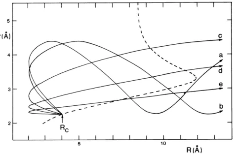
Figure 2.4 - Trajectories on the ionic surface for the Na+ + Br2- system at impact parameter b = 2 A, and collision velocities (a) 4 × 10³ ms-1, (b) 5 × 10³ ms-1, (c) 104 ms-1, (d) 2 × 10⁴ ms-1, and (e) 4 × 10⁴ ms-1. The dashed line denotes the seam between the covalent and ionic surfaces. All trajectories are assumed to switch to the ionic surface at R = Rc and at the equilibrium bond length, r = re, of the Br2 molecule, but the probability of return to the covalent surface is a decreasing function of the coordinate R at the point at which the trajectory re-crosses the seam [19]. ... 24
Figure 2.5 - Schematic neutral and anionic potential energy curves for a generic halogen molecule BB ... 26
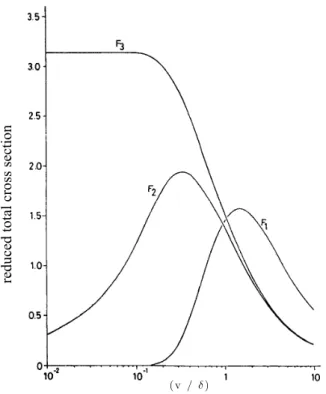
Figure 2.6 - Reduced total cross sections: F1 defines the atom-atom interaction; F2 defines the atom rigid-molecules interaction and F3 defines the atom-molecule interaction considering ... 27
Figure 3.1 - Experimental schematics: a) Potassium oven; b) Charge exchange oven; c) Potassium ion source; d) Deflecting plates; e) Langmuir-Taylor detector; f) Bio oven; g) TOF mass spectrometer ... 30
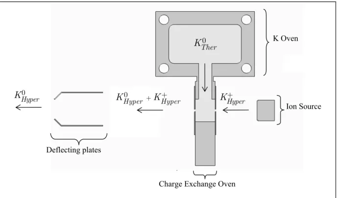
Figure 3.2 - Charge exchange schematics ... 31
Figure 3.3 - Charge exchange source: a) Charge exchange oven; b) Potassium oven; c) K+ Ion source; d) Deflecting plates ... 33
Figure 3.4 - K+ Ion Source ... 34
Figure 3.5 - Ion source support: a) Ion source ... 35
Figure 3.6 - Langmuir-Taylor detector ... 37
Figure 3.7 - Dependence of beam intensity as function of the potassium oven temperature ... 39
Figure 3.8 - Dependence of beam intensity with respective acceleration energy ... 40
XVI
Figure 3.11 - Biomolecules' Oven: a) Capillary tip; b) Outer Body; c) Container ... 44
Figure 3.12 - Basic TOF configuration ... 46
Figure 3.13 - Dual-Stage TOF mass spectrometer ... 47
Figure 3.14 - Single-stage TOF focal plane ... 53
Figure 3.15 - Comparison of single-stage (a) and dual-stage (b) extraction ... 53
Figure 3.16 - Two ions with different initial kinetic energies ... 55
Figure 3.18 - Extraction system: a) Extraction region; b) Acceleration region; c) Einzel lens; d) Deflecting plates; e) Flight tube ... 58
Figure 3.17 - Schematics of the implemented TOF spectrometer ... 58
Figure 3.19 - TOF extraction system electrical connections ... 59
Figure 3.20 - Schematics of channeltron pulsed mode electrical connections for negative ion detection ... 60
Figure 3.21 - Energy resolution dependence with the ion kinetic energy release ... 62
Figure 3.22 - NO2– peak of nitromethane mass spectrum at different acceleration voltages ... 64
Figure 3.23 - NO2– peak of the nitromethane mass spectrum at different einzel lens voltages ... 65
Figure 3.24 - TOF calibration curve (3º Iteration) ... 68
Figure 3.25 - Nitromethane anions TOF mass spectrum assignment from the collision of an effusive nitromethane beam and a 100eV neutral potassium beam. ... 69
Figure 3.26 - MCDWIN Software ... 72
Figure 3.27 - Labview program control layout ... 73
Figure 3.28 - Acquisition Layout ... 74
Figure 3.29 - Acquisition system time diagram ... 75
Figure 3.30 - Nitromethane TOF mass spectra in pulsed and continuous operation modes ... 76
Figure 3.31 - Nitromethane partial spectra with different collision delays for a ... 77
Figure 3.32 - Vacuum system schematics ... 78
Figure 4.1 - Three-dimensional schematic representation of nitromethane molecule ... 81
Figure 4.2 - Nitromethane TOF anion spectrum at a collision energy of 183 eV [27]. ... 85
Figure 4.3 - Nitromethane TOF anion spectra at three collision energies ... 86
Figure 4.4 - Nitromethane Partial Cross Section ... 87
Figure 4.5 - Schematic potential energy curves taken from [45] for neutral ground-state CH3NO2 and the two lowest-lying anion states, 2 1( *) B p , and 2 1( *) A s . ... 90
Figure 4.6 - Negative ion TOF mass spectrum of K + CD3NO2 at 100 eV collision energy ... 92
Figure 5.1 - Schematic representation of a) Thymine and b) Uracil. ... 97
Figure 5.2 - Thymine TOF anion mass spectra at 30, 70 100 eV collision energies ... 104
XVII
Figure 5.5 - The line drawn with circles () represents the ion yield as a function of the electron energy of [T-H] – upon DEA to the NB embedded in He droplets at 0.37 K. The solid line () shows the anion efficiency curves of [T-H] – while the dashed line (----) represents the sum of all other observed product anions, upon DEA to the corresponding bare nucleobase molecules.
(Adapted from [73]) ... 113
Figure 5.6 - Computed real parts of the A´ and A´´ resonance energies as a function of ring-breaking deformations in uracil. The left panel deals with the C3-N5 stretch while the right panel is for the C4-N2 stretch [69]. ... 114
Figure 6.1- Schematic representation of a) 5-chlorouracil and b) 5-fluorouracil. ... 122
Figure 6.2 - 5-chlorouracil TOF anion mass spectra at three collision energies ... 127
Figure 6.3 - 5-fluorouracil TOF anion mass spectra at three collision energies ... 129
XIX
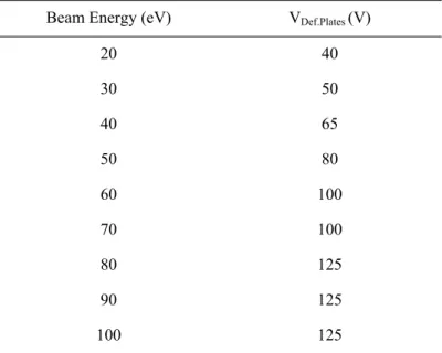
Table 3.1 - Deflecting plates extraction voltage as a function of the potassium beam energy ... 36
Table 3.2 - SIMION results ... 42
Table 3.3 - NO2– peak characteristics at different acceleration voltages ... 64
Table 3.4 - Mass Calibration Iterations ... 66
Table 3.5 - HP 214B Specifications ... 70
Table 3.6 - FastComtec P7888 Specifications ... 71
Table 3.7 - Extraction delays ... 76
Table 4.1 - Experimental acquisitions parameters ... 84
Table 4.2 - Nitromethane negative ions assignment and respective relative partial cross sections at several collision energies ... 87
Table 5.1 - CM framework collision energy conversion ... 99
Table 5.2 - Experimental acquisition parameters used to measure Thymine ... 100
Table 5.3 - Experimental acquisition parameters used to measure Uracil ... 100
Table 5.4 - Thymine negative ions assignment and related relative partial cross sections at several collision energies ... 105
Table 5.5 - Uracil negative ions assignment and respective relative partial cross sections at several collision energies ... 107
Table 5.6 - Comparative tables on the DEA and electron transfer to thymine (left) uracil(right). ... 108
Table 6.1 - CM framework collision energy conversion ... 124
Table 6.2 - Experimental acquisition parameters used to measure 5-chlolouracil ... 124
Table 6.3 - Experimental acquisition parameters used to measure 5-fluorouracil ... 125
Table 6.4 - 5-chlorouracil negative ions assignment and relative partial cross sections at several collision energies ... 128
Table 6.5 - 5-fluorouracil negative ions assignment and respective relative partial cross sections at several collision energies ... 130
XXI
1-MeT 1-methil-thymine
3-MeU 3-methil-uracil
5-ClU 5-Chlorouracil
5-FU 5-Fluorouracil
5-BrU 5-Bromouracil
a
a Acceleration in the extraction region
b
a Acceleration in the acceleration region
a.m.u Atomic mass units
a.u. Arbitrary units
a Spatial orientation coordinate
b Impact parameter
CAD Computer aided design
CE Charge Exchange
CM Centre of Mass
d Acceleration region length
D Drift region length
DBS Dipole-bound state
DC Direct current
DEA Dissociative electron attachment
DFT Density functional theory
DNA Deoxyribonucleic acid
DSB Double strand Breaks
/ cov ion
D Energy difference between the covalent and ionic surfaces
ΔfHgo Enthalpy of formation
CM
E Energy in the centre of mass framework
( )
EA r Molecular electron affinity
e Electronic Hamiltonian eigenvalue
E Energy
0
e Internal motion Hamiltonian eigenvalue
e- Single electron
effec
E Effective energy
b
E Electric field between first grid and the second grid
a
E Electric field between repeller plate and the first grid
Lab
XXII
EAadiabatic Adiabatic electron affinity
EAv Vertical electron affinity
EThreshold Threshold energy
ETS Electron Transmission Spectroscopy
( )
f a Angular function of the molecular spatial orientation
F Force
FWHM Full-Width Half-Maximum
el
H Electronic Hamiltonian
H Hamiltonian
h Planck constant
Reduced Planck constant
H0 Hamiltonian for the internal motion
H11;H22 Diabatic potential curves (diagonal coupling matrix elements)
H12;H21 Diabatic coupling terms (non-diagonal coupling matrix elements)
Measured
I Measured electrical current
REL
I Relative electrical current
Displayed
I Displayed electrical current
IE Ionisation energy
0 Hyper
K Hyperthermal potassium atom
Hyper
K+ Hyperthermal potassium ion
K+ Potassium cation
0 Ther
K Thermal potassium atom
k Electronic state
K Potassium
K0 Neutral potassium
LEE Low energy electrons
LUMO Lowest unoccupied molecular orbital
0 Hyper
M Hyperthermal Alkali atom
Hyper
M+ Hyperthermal alkali ion
Kinetic
M Mass resolution associated with initial kinetic distribution of the ions
Spatial
M Mass resolution associated with initial spatial distribution of the ions
p
m Projectile mass
t
XXIII Ther
M Thermal alkali ion
Total
M Total mass resolution
m Mass
m/z Mass to charge ratio
MO Molecular orbital
µ Dipolar moment
NB Nucleobase
Frequency
P Inelastic scattering probability
p Landau-Zener probability
PES Potential energy surface
PID Proportional integral derivative
Pt100 Platinum resistance thermometers
( ; )q R
f Adiabatic electronic wavefunctions
0 ( ;q R ); ( )q
f f Diabatic electronic wavefunctions
*
p antibonding orbital
Y Total wave function
q Electronic coordinates
Q Total cross section
q Electrical charge
1 c
R First crossing radius
2 c
R Second crossing radius
R Nuclear coordinates
Rc Crossing radius
RET Rydberg Electron Transfer
RNA Ribonucleic acid
Ro Fixed internuclear distance
r Vibrational coordinate of the diatomic molecule
s Covered length in the extraction region
S Extraction region length
SSB Single strand breaks
*
s antibonding orbital
b
t Time spent in the acceleration region
a
t Time spent in the extraction region
TOF
XXIV
D
t Drift region flight time
b
t Acceleration region flight time
D
t Drift region flight time
a
t Extraction region flight time
T Thymine
tcol Collision time
TNI Temporary negative ion
TOF Time of Flight
tvib Vibration period
0
U Initial kinetic energy
b
U Kinetic energy acquired in the acceleration region
a
U Kinetic energy acquired in the extraction region
U Total kinetic energy
( ) i
U r Undistorted Morse potential of the free X2- molecular ion
( ) c
U r Morse potential of the free X2molecule
U Uracil
( ) c
V R Isotropic Lennard-Jones potential for the M +X2 interaction on the covalent surface
k
V + Potassium cations acceleration voltage
( , ) i
V Ra Anisotropic potential describing the M+ +X2- interaction
0
v Ions initial velocity
b
v Ions velocity as they enter the acceleration zone
D
v Ions velocity as they enter the drift region
cov
V Covalent potential curve
( ; )
V q R Interaction potential
ion
V Ionic potential curve
r
v Radial velocity
v Velocity
cov( , )
V R r Covalent potential surface
( , , ) ion
V R r a Ionic potential surface
b
XXV
a
V Extraction region voltage
VDef.Plates Deflecting plates voltage
VFR Vibrational Feshbach Resonance
0; 0
x s Ion initial position
b
x Starting point of acceleration region
D
x Starting point of the drift zone
( )R
c Nuclear wavefunctions
1
1.1 Radiation effects on biological systems
Over the last years, the international scientific community has taken a special interest in better understanding the various processes capable of damaging and mutating living cells, especially when these might be directly related to the development of severe physiological disorders. Indeed, it is quite well established that ionising radiation (X-rays, -rays, ions, protons and electrons) is capable of, within the early stages of irradiation (~10-16 s after interaction), triggering mechanisms that, in the long term eventually result in cellular damage. The effects (direct and indirect) of such radiation have been acknowledged as one of the most significant mechanisms when dealing with structural and functional deviations at the cellular level. These deviations can result in cellular mutations, impairment and eventually lead to the development of oncological pathologies.
Owing to its high capability of DNA damage, ionising radiation is also currently used in radio therapeutic treatments as a mean of destroying cancer cells but, as effective as it may be, it is also responsible for destroying and damaging the surrounding healthy cells. In order to increase the effectiveness of such radio therapeutic processes, the interactions of ionising radiation with the physiological constituents should be described not only by the macroscopic evidences of structural impairment (in terms of energy deposition), but more importantly, it must be understood in terms of the fundamental molecular mechanisms that precede cellular damage.
2
Figure 1.1 - Chronological diagram of radiation induced damage
Over the last century, a significant amount of research efforts were conducted in order to understand the effects (direct and indirect) of high-energy radiation interaction with biological systems, especially with DNA and living cellular tissue. The majority of biological effects carried out by high energy radiation is not associated with direct interactions with the biological material, but are instead related to secondary species created upon direct irradiation [1]. Such secondary species (free electrons, radicals, ionic species) can be more reactive and potentially more damaging than the primary radiation responsible for their formation. As these secondary species may interact with the surrounding medium, favourable conditions are in order for genotoxic, mutagenic and other potentially lethal DNA degradation (DNA and desoxiribose structural damage, DNA basis liberation, single and double strand breaks, among many others [1-5]).
3
molecules within the physiological medium, producing high quantities of radicals, cations and anions, which can in turn induce further damage.
1.2 Direct and indirect DNA damage
As mentioned above, the majority of DNA damages are induced by secondary species that are created upon the interaction of ionising radiation with the biological material. However, until recently, damage to DNA was thought to be due to the direct interaction of high energy radiation (α, , or x-rays) only. However, in a landmark research publication the group of Sanche and co-workers have experimentally shown that, upon low energy electron beam irradiation (3 to 20 eV) of thin films of plasmid DNA, the number of single strand breaks (SSB), double strand breaks (DSB) and loss of supercoiled helicity (phosphate–ester bond breakdown) showed a resonant-like behaviour [6]. The results have also shown that electron induced DNA damage with energies far below the ionisation energies of its molecular constituents [1], can actually happen at energies as low as 3 eV, followed by a relatively intense structure (resonance) at 10 eV. This behaviour is significantly different from the photon induced DNA damage results, showing an energy threshold around 7 eV followed by a linear increase until it reaches 12 eV. Beyond that, the amount of damage stabilizes for increasing energies during the next hundreds of eVs [6]. Furthermore, when comparing the damage efficiency of a single photon against damage efficiency of single low energy electron, it is possible to realize that 30 photons are necessary to operate a DNA strand break or helicity loss whereas only 4 secondary electrons are needed to achieve the same damage level.
It was also shown that secondary electrons are more efficient in terms of operating DNA damage, with respect to direct radiation related damage. Adding all this to the fact that secondary electrons are one of the most abundant secondary species created upon irradiation, it became rather evident that low energy electrons may play an important role when as far as radiation related DNA damage is concerned. In fact, both Boudaiffa et al. [6] and Lennert et al. [7] suggest that 70% of the DNA damage is associated to secondary low energy electrons and that only 30% of the damages are related to direct deposition of energy.
In the course of successive inelastic collisions within the medium these electrons are thermalized and become solvated within 10-12 s. The relevance of reactions of presolvated
4
Following Sanche´s work, several theoretical and experimental studies concerning dissociative electron attachment processes have been performed, especially on biological relevant molecules (DNA basis, RNA basis, sugars, among many other).
Electron attachment processes can be described as the interaction of a single electron (e-) and a generic molecule (AB), as follows:
*
( ) ( )
e- +AB AB- AB- +hn (1.1)
* *
( )
e- +AB AB- AB +e- (1.2)
(
e-+ABbbbbbbbbbbb AB A+B o- r A- +B (1.3)
In these reactions, the free electron is captured by the molecule leading to the formation of excited temporary negative ion (TNI), in a so-called metastable state (or quasi-stable state). These electrons are attached to the molecule for a short time period (of the order of 10-16 s) through a resonant attachment process, which can only occur for electrons of appropriate energy [9]. This can be seen as the accommodation of the extra electron to one of the normally unoccupied molecular orbitals (MOs), which depending on the electron affinity (positive or negative) of the target molecule can either be a lowest unoccupied molecular orbital (LUMO) or a higher lying virtual MO [9].
After the TNI is created, several reaction paths can follow. In one of them, the molecule is capable of accommodating the “extra” electron but the excess of internal energy causes a photon to be emitted (equation (1.1)). This process is known as radiative stabilization and it is characterized by reaction times between 10-8 and 10-9s.
Another reaction channel is characterised by the auto-detachment of an electron from the TNI, as in equation (1.2). In this reaction, the molecule AB suffers no dissociation and becomes neutral once again, but it can remain in a vibrational excited state. The interaction time of such reactions depends greatly on the size of the molecule, but normally of the order of 10-12 to 10-14 s.
Finally, in equation (1.3), is presented the dissociative electron attachment, which at the molecular level is believed to be responsible for most of the damage on biological structures (direct DNA damage). In this process, the TNI dissociates due to the instability created by the “extra” electron, which not only changes the intramolecular potential but also adds an excess of internal energy that ultimately results in the TNI dissociation. The presence of such process greatly depends not only on the energy of the incoming electron (resonant process) but also it can be site and bond selective, i.e. this process can selectively occur depending if the electron is captured into certain regions of the molecule and, if so, it can selectively induce molecular dissociation of specific chemical bonds [10].
5
molecules or ions with unpaired electrons on an open shell configuration that may have positive, negative, or zero charge. If allowed to diffuse, they can be potentially quite damaging to other molecules. Considering that 70% of the cells are composed of H2O, water radiolysis can also play an
important role in the formation of free radicals. In this case, however, their formation is not accomplished by dissociative electron attachment processes, but instead by means of radiation induced ionisation of water molecules (equation (1.4)), that will further react with neutral H2O molecules and
eventually lead to OH radical formation (equation (1.5)).
2 2
H O +hn H O+ +e- (1.4)
2 2 3
H O+ +H O H O+ +OH· (1.5)
1.3 Electron transfer processes
Since the discovery of the capability of secondary electrons to cause SSB’s and DSB’s in DNA, a significant interest in the study of the various DNA constituents in the gas-phase has raised considerable interest in the international research community. Extensive studies on DEA have already been performed to the molecular constituents of the DNA, namely to the isolated DNA bases or sub-units. However, free electron attachment processes may be not sufficiently enough to completely describe the molecular reactions within the physiological medium. In this environment, “free” electrons have very limited lifetimes, i.e. through inelastic scattering electrons will quickly lose energy to the medium and eventually react with or be solvated by the surrounding molecules. As such, these collisions are defined not only by the free electrons and the “target” molecules but also by the molecules in the surrounding medium, especially the molecules from which the electrons were initially ejected. In this context, studies on electronic capture of ‘bound’ electrons (as in atom-molecule collisions) may present a good alternative to better simulate the molecular damage processes induced by secondary electrons at cellular level.
In atom-molecule collisions, a neutral atom (A) possessing a weakly bound electron acts as an electron “donor”. When the collision with a molecule (BC) occurs, an electron may be ejected from the source atom A to the “target” molecule BC. After that, several reaction channels may occur, as presented below:
A+BC A++BC- (Non Dissociative Ionisation) (1.6)
A+BC A+ +B- +C (Dissociative ionisation) (1.7) (Dissociative ionisation) (1.8)
( )
-6 A+BC AB+ +C +e- (Dissociative ionisation) (1.9)
A+BC AB +C+ +e- (Dissociative ionisation) (1.10)
A+BC AB+ +C- (Reactive chemical ionisation) (1.11)
A+BC ABC+ +e- (Associative chemical ionisation) (1.12)
A+BC A+B+ +C- (Polar dissociation) (1.13)
The electron transfer processes, may also be pictured in two separate stages. First it is necessary for the neutral atom (A) to undergo ionisation in the surroundings of the “target” molecule (BC). The ejected electron must then be captured by the molecular target (BC), leading to the formation a TNI.
This process greatly depends on two key physical properties. One is the ionisation energy (IE) of the electron “donor” atom (A) and the other is the electron affinity (EA) of the “target” molecule (BC). EA is defined as the amount of energy needed for the electron to detach from the negative ion to the neutral and is designated as EAadiabatic when referring to adiabatic electron affinity or by EAv when
referring to vertical electron affinity. Another important physical property as far as atom-molecule collisions are concerned is the endoergicity of the process, shown in equation (1.14). If the ionisation energy is higher that the electron affinity, the endoergicity is positive, meaning that the process is endothermic.
( ) ( )
E IE A EA BC
D = - (1.14)
Following electron transfer processes in atom-molecule collisions, it is possible for certain amounts of excessive internal energy to be transferred back to the positive species A+. This is in contrast to electron-molecule systems where such release of internal energy (to a third body) is not possible, at least within a time frame capable of competing with autodetachment and dissociation processes. In comparison to free electron attachment, atom-molecule collisions can induce the formation of stable parent ions (BC–), change the probability for certain reaction channels or even induce the formation of additional fragmentation channels. Nevertheless, the set of results presented in this thesis suggest that the basic interactions of secondary radiolytic species, such as nonthermal free electrons, may in general disrupt the natural chemistry of DNA. Thus, a detailed knowledge of resonant electron induced damage to most of the chemical species found in cells will be required before a complete understanding of the nascent effects of ionising radiation on living tissue can be achieved.
7
crossed beam experimental setup (Chapter 3 ) to investigate negative ion formation induced by charge transfer processes between neutral potassium atoms (K) and isolated biomolecules.
Neutral potassium atoms are used as electron “donors” due to their low ionisation energies (IE(K) = 4.34 eV). Even though neutral potassium does not exist in the physiological environment, it could provide some insight on the role of charge “carriers” in the degradation of DNA molecules caused by low energy secondary electrons. Being so, and following the use of nitromethane as calibration molecule, studies of negative ion formation on DNA basis (thymine), RNA basis (uracil) and halouracils (5-chlorouracil and 5-fluorouracil) were performed. A comprehensive comparison was also established between DEA results and the results presented within this thesis.
9
Collision Theory and Ion Pair Formation
In this chapter a general formulation of the collision problem applied to the atom-atom collision will be presented, followed by the ion-pair formation probability given by the Landau-Zener formula. The problem arising from collision involving more complex systems will also be discussed followed by an introductory and conceptual presentation of a few models used to simplify the problem, namely for atom-diatomic collisions.
2.1 Two-Particle Collision
10
2.1.1
Born-Oppenheimer approximation: Adiabatic
Framework
The interaction between two particles can be described in quantum mechanics by the Schrödinger equation
,
HY = YE (2.1)
which can be alternatively [13] expressed as
0 H E
é - ùY =
ë û (2.2)
The Hamiltonian H can be written as
( ) ( ; ) n el
H =T R +H q R , (2.3)
in which the nuclear coordinates are described by R and the electronic coordinates by q. The term
( ) n
T R is the kinetic energy operator that describes the motion of the nuclei and H q Rel( , )is the electronic Hamiltonian, which contains electronic kinetic energy operator and the nuclear Coulomb interactions that depends parametrically on the nuclear coordinates (in this formulation the spin-orbit coupling is ignored).
The first step of the Born-Oppenheimer approximation consists in separating the nuclear motion from the electronic motion. Towards that end, the total wavefunction Y( ; )q R is expanded in a complete, orthogonal set of adiabatic electronic wavefunctions f( ; )q R that depend parametrically on the nuclear coordinatesR. In other words the nuclear motion is considered to be slow, allowing the electrons to adjust their positions for each new internuclear distance. The total wavefunction can now be written as
( ; ) k( ; ) k( ) k
q R f q R c R
Y =
å
, (2.4)in which ck( )R is the nuclear wave function associated with each electronic state k .
Replacing equations (2.4) and (2.3) in (2.2) we obtain
[ n el ] ( ; )k k( ) 0 k
T +H -Ef q R c R =
å
(2.5)11
(1) (2)
( ; ) ( ) ( ; ) ( ) ( ; ) ( ) 0
n k k el k k k k
k
T f q Rc R H f q Rc R Ef q Rc R
é ù
êé ù é ù ú
êë û +ë û - ú=
ê ú
ê ú
ë û
å
. (2.6)In the first term of equation (2.6), the adiabatic electronic wave functions are derived
assuming that fk( ; )q R are slowly varying functions of R, meaning that the terms like k( ; )q R R f
¶ can be
neglected. Therefore it is possible to write:
[Tn] ( ; ) ( )fk q Rck R =fk( ; ).[q R Tn] ( )ck R (2.7)
Regarding the second term of equation (2.6), if we consider that the differentiation terms within the electronic Hamiltonian [Hel] are operated only with respect to the electronic coordinates q, is
possible to write
[Hel] ( ; ) ( )fk q Rck R =ck( ).[R Hel] ( ; )fk q R , (2.8)
where fk( ; )q R are the eigentstates (known as adiabatic states [14]) of the electronic Hamiltonian given by
[Hel] ( ; )fk q R =ek( ) ( ; )Rfk q R , (2.9)
meaning that equation (2.8) can be expressed as
[Hel] ( ; ) ( )fk q Rck R =ek( ) ( ; ) ( )Rfk q Rck R (2.10)
If equation (2.7) and (2.10) are replaced in equation (2.6) we obtain
( ; ).[ ] ( ) ( ; ) ( ; ) ( ) 0
k n k k k k
k
q R T R q R E q R R
f e f f c
é + - ù =
ë û
å
(2.11)By multiplying the above equation from the left by each of the basis functions fi( ; )q R and
integrating over q[13], we obtain:
( ; ) [ ] ( ) ( ; ) ( ) 0
i n k k k
k
q R T R E q R R
f e f c
é + - ù =
ë û
å
, (2.12)which from the orthogonality of the basis becomes
[Tn] ei( )R E ci( )R 0
é + - ù =
12
Equation (2.13) represents the Born-Oppenheimer set of coupled equations (in an adiabatic framework), where each electronic eigenvalue ei(R) will give rise to a full internuclear potential
energy surface (known as Born-Oppenheimer surface), that is parametrically dependent on the internuclear distance.
However, these surfaces can (and often do) become coupled by the so called non-adiabatic effects, contained in the terms that have been neglected in approximation in equation (2.7), meaning that the Born-Oppenheimer approximation is violated. For example, when a transition between two adiabatic states of the same symmetry occurs (knowing that the respective potential surfaces cannot cross each other [14]), the Born-Oppenheimer principle is not fulfilled. In this case the complete Hamiltonian is no longer diagonal in the electronic basisfk( ; )q R , meaning that the adiabatic electronic
states k are coupled by the terms involving the nuclear kinetic energy operator neglected above. This
corresponds to the fact that if two adiabatic states of equal symmetry come together, the non-crossing rule forces the respective wave functions to significantly change their character. If, however, two particles come across each other along one of these states with high velocity, the time spent in the avoided crossing region could be too short for the electrons to adjust their positions. This means that the system violates the non-crossing rule and moves along a so-called diabatic potential curve [14].
2.1.2
Born-Oppenheimer approximation: Diabatic
Framework
The major difference between the diabatic and adiabatic approach of the collision problem is that, in the diabatic framework, the total wavefunction Y( ; )q R is expanded in a complete, orthogonal
set of diabatic electronic wavefunctions f( ;q R0) that no longer depend on the nuclear coordinates R
and are determined for a fixed internuclear distance R0 (normally at infinite separation). In other
words, the collision partners’ motion is considered to be so fast that the electronic states will keep the same character independently of the nuclear distanceR.
In the diabatic framework the Hamiltonian H should be written as
0 ( ) ( ; ) ( )
el
n
H
13
where T Rn( ) is the kinetic energy operator that describes the motion of the nuclei and where the
electronic Hamiltonian H q Rel( , ) has been divided in two parts, the interaction potential V q R( ; ) and
the Hamiltonian for the internal motion H q0( ). The total wavefunction can be written as
( ; ) k( ) k( ) k
q R f q c R
Y =
å
, (2.15)in which nuclear coordinates are described by R and the electronic coordinates by q and ck( )R is the
nuclear wavefunction associated with each diabatic electronic state k .The orthonormal set of
electronic wavefunctions fk( )q are the eigenstates of H q0( )that is given by
0 0
[H q( )] ( )fk q =e fk k( )q . (2.16)
If equations (2.15) and (2.14) are replaced in the Schrödinger’s equation (2.2), we get
0
[ n( ) ( ; ) ( ) ] ( )k k( ) 0 k
T R +V q R +H q -Ef q c R =
å
, (2.17)which from equation (2.16) can be written as
0
[ n( ) ( ; ) k ] ( )k k( ) 0 k
T R +V q R +e -Ef q c R =
å
(2.18)Contrarily to the approximation needed in the adiabatic framework, in this case the nuclear kinetic energy operator when operated on the electronic wavefunction will be null, since fk( )q does not depend on the nuclear coordinateR.
By multiplying the left terms of equation (2.18) each of the basis functions fi( )q and integrating
over q [13], it is possible to obtain:
0
( ) [ ]( ) ( ) ( ) ( ; ) ( ) ( ) 0
i n k k i k k
k
q T R E q q V q R q R
f e f f f c
é + - + ù =
ê ú
ë û
å
(2.19)which from orthogonality of the basis becomes
0
[ n( )] ii( ) i i( ) ik( ) ( )k 0 i k
T R V R e E c R V Rc R
¹
é + + - ù + =
ê ú
ë û
å
, (2.20)with Vik = fi( )q V q R( ; )fk( )q
14
0
11 1 1
0 1 ( ) ( ) [ ( )] ( ) ( ) k el
i ik i
V R V R
H R
V R V R
e
f f
e
æ + ö÷
ç ÷
ç ÷
ç ÷
ç ÷
= çç ÷
÷÷
ç ÷
ç + ÷
çè ø
(2.21)
where diagonal elements (i =k) represent the diabatic potentials, which are coupled by the
off-diagonal elements (i ¹k) of the interacting potential Vik( )R .
In the diabatic framework an atom-atom collision between an alkali atom (A) and a halogen atom (B) can be described within the two states approximation, where the collision is defined by inelastic processes where only two diabatic states are relevant. The covalent wavefunction f1 is
associated with the electronic state (A+B) and an ionic wavefunction f2 is associated with the
electronic state (A++B–). In this case the electronic Hamiltonian of the electronic diabatic wavefunctions f1and f2 is given by
0
11 1 12 11 12
0
21 22
21 22 2
( ) ( )
[ ( )]
( ) ( ) el
V R V R H H
H R
H H
V R V R
e
f f f
e
æ + ö÷ æ ö
ç ÷ ç ÷
ç ç ÷
=çèçç + ÷ø÷÷ =èçç ÷ø÷÷ (2.22)
where 11 12 21 22 H H H H æ ö÷ ç ÷ ç ÷ ç ÷÷
çè ø is the coupling matrix between the ionic and covalent states and, as mentioned
above, the diagonal terms H11 and H22 describe the diabatic potential curves that are coupled by the
terms H12and H21. These coupling terms can be considered equivalent (H12 =H21) if magnetic
interactions (introducing quadrupolar, octapolar, … terms) are neglected [14].
From the diagonalization of this coupling matrix, the adiabatic states can be easily found:
(
)
2 21,2 11 22 22 11 12
1
4 2
E = çæççèH +H H -H + H ö÷÷÷
ø. (2.23)
From the previous equation is possible to conclude that when H12 is very small in respect to
22 11
H -H (i.e. away from the crossing pointRc ) the adiabatic and diabatic states will show a similar
behaviour (as observed in Figure 2.1). On the other hand, in the vicinity of Rc where
11( c) 22( )c
H R =H R , these states show a different behaviour, as the diabatic cross and the adiabatic do
not. At this internuclear distance the energy gap between the adiabatic states is given by 2H12( )Rc .
15
12
(H (Rc)=0) which, from the non-crossing rule, could only happen if the two wavefunctions that
describe these adiabatic states show different symmetry and multiplicity.
The analysis of the curve crossing schematically presented in Figure 2.1 can be very useful when trying to understand the atom-atom collision process (ion-pair formation) from the charge transfer (electron jump) point of view.
Figure 2.1 – Schematics of the potential energy curves: adiabatic states E1 and E2 - full curves; diabatic
states H11 (covalent) and H22 (ionic) - dashed curves, where Rc designates the crossing radius
Considering that two atoms on the covalent state
(
A+B)
are approaching each other andreach the crossing point, one of two processes can occur. If the crossing is passed adiabatically the electronic wavefunctions will present a dramatic change in their character, meaning that an electron jump has occurred leading to ion-pair formation
(
A+ +B-)
. If, however on the other hand, thecrossing is passed diabatically, the electronic wavefunctions will maintain their character and no electron jump will occur, which leaves the collision partners in the same covalent state as before, i.e.
(
A+B)
.After the first crossing and as the atoms come close together, they start to move apart, eventually reaching the crossing point again. If this second crossing is reached from the covalent state
(
A+B)
, the cross can once again be passed diabatically leading to(
A+B)
where no electron jump H22H11
E2
E1
A++ B
-A+ B E
R
16
has occurred, or it can be passed adiabatically leading
(
A+ +B-)
where an electron jump took place.If the second crossing arises from the ionic state
(
A+ +B-)
, the cross can be passed diabaticallyleaving the atoms in the same ionic state
(
A+ +B-)
, or it can be passed adiabatically wherereneutralization occurs leading to the covalent state
(
A+B)
.From the analysis performed above is possible to conclude that, after the collision, the atoms are left in the ionic state (ion-pair formation) if the crossings are passed first diabatically and then adiabatically or vice-versa (often called non-adiabatic transitions).
2.1.3
Landau-Zener model
The Landau-Zener formula was obtained by solving the time-dependent Schrödinger equation for a simple one dimensional, two state system where it was assumed that colliding particles follow a given classical trajectory [12]. This model assumes a single collision coordinate described by the
internuclear distance R t( ), a constant and equivalent collision radial velocity r ( )
R t v
t
æ ¶ ö÷
ç = ÷
ç ÷
ç ÷
çè ¶ ø for both
electronic states around the crossing point Rc (straight trajectory) [15].
The time-dependent Schrödinger equation was solved within the diabatic framework and from it the probability p was derived, defining the probability for the two-particle system to stay in the diabatic potential energy curve (i.e. the probability of passing Rc diabatically) [14]. As such, the
Landau-Zener formula for the diabatic transition probability is then given by:
(
)
2 12
11 22 2 ( ) exp c c r R R H R p d
v H H
dR p = æ ö÷ ç ÷ ç ÷ ç ÷ ç ÷ ç ÷
= çç- ÷÷
÷
ç ÷
ç - ÷
ç ÷
ç ÷
çè ø
(2.24)
where vr defines the collision radial velocity and where H12,H11 and H22 are taken from the diabatic
coupling matrix in equation (2.22) described in the previous section.
The classical trajectory approximation used in the Landau-Zener derivation is more accurate for high velocity collisions where a straight line trajectory can be considered. These straight line collision trajectories are described by the impact parameter method (illustrated in Figure 2.2 ), where the system moves along a trajectory given by:
2 ( )2
17
When the electron jump occurs at the first crossing, the scattering happens along the “ionic” path (red line). If no electron jump occurs at the first crossing, the scattering happens along the “covalent” path (blue line). It is important to note that both ionic (dashed lines) and covalent states (full lines) can result from the so-called “covalent” or “ionic” paths.
Considering that the outcome of the two particle collision is described within the impact parameter model through four different trajectories (if b <Rc) , it is possible to realize that two of
them give rise to ionic states (inelastic scattering) and the other two are responsible for covalent states (elastic scattering). Being so, it is possible to express the probability of ion-pair formation using equation (2.24), as follows
Pinelastic scattering =p(1-p)+(1-p p) =2 (1p -p) (2.26)
where p(1-p) represents the probability for passing the first crossing diabatically and the second adiabatically. The term (1-p)p represents the other case, where the first crossing is passed adiabatically and the second diabatically.
Rc
b
A+B
A+B A++B–
A++B– RC
“Ionic” path
“Covalent” path
18
2.1.4
Atom-Atom Collisions
As reported before, when two neutral atoms collide in their ground state, two separate processes can occur. One of them is identified as elastic scattering, meaning that after the collision the atoms are left in the covalent state where both species are kept neutral and where the total kinetic energy of the system is conserved. The other process is inelastic scattering, where the atoms undergo a charge exchange mechanism and after the collision are left in an ionic state, where no conservation of total kinetic energy of the system is observed. As such, these inelastic scattering processes are extremely relevant to the analysis of the negative ion formation through electron transfer processes (the topic of this thesis).
To characterise the electron transfer processes in atom-atom collisions we will consider the following alkali-atom iodine-atom collision
Na+ I Na+ +I- (2.27)
The relevant diabatic covalent (Na+I) and ionic (Na+ +I-) states are described by the
potential energy curves shown in Figure 2.3. Considering that both states are of the 2
å
+ type and have the same symmetry, the corresponding adiabatic potential curves will show an avoided crossing point at Rc[12].Figure 2.3 - Approximated diabatic potential energy curves for the lowest diabatic sates of Na-I .
cov
V andVion are the diabatic potentials corresponding to the covalent and ionic electron configuration
respectively. DE is the difference between the ionization potential Naand the electron affinity of I [12].
2 2
1/2 3/2 Na( S )+I(S )
E
cov
V
ion
V
1 1
0 0
Na (+ S )+ I (- S )
19
The separation between the diabatic potentials Vcov and Vion at infinite N a -I internuclear distance is given by
E IE EA
D = - , (2.28)
where IE is the ionisation energy of the alkali atom, Na(5.14eV), and EA is the electron affinity of
the halogen, I(3.06eV) [12]. Considering that the crossing point Rc occurs at large internuclear
distances, is possible to neglect the Van der Waals and induction forces, which means that the covalent potential can be considered zero and that the ionic potential can be given by a Coulombic potential. Though, the crossing point is given by
14.41 c
R
E
=
D (2.29)
where Rc is expressed in Å and DE in eV.
When Rc is reached, transitions between two diabatic states can occur (i.e. the crossing point
is passed adiabatically) if the relative kinetic energy is larger thanDE . In other words, the electron can jump from the alkali atom to the halogen atom if there is sufficient kinetic energy between the atoms for the system to go from the covalent to the ionic state. However, if the impact parameter
c
b<R (see Figure 2.2) the crossing point will be passed twice and electron transfer is possible on
either crossings, yielding four different trajectories.
For ion-pair formation, the electron jump should merely occur at the first or at the second crossing, which will only happen within two trajectories (inelastic scattering). If the electron jump occurs at both crossings or if does not occurs at all (within the same trajectory), no ion-pair formation will happen (elastic scattering).
To evaluate the ion-pair formation probability, the Landau-Zener formula (2.24), presented in section 2.1.3 , was used. If Vion is assumed to be given by a Coulomb potential and Vcov through a constant, the Landau-Zener formula can be simplified to
2 12
2 ( )
exp
( ; ) c c
r c
H R R
p
v b R p
æ ö÷
ç ÷
ç
= çç- ÷÷÷
è ø (2.30)
where all units are defined in atomic units. The coupling element H12 is evaluated atRc and the radial
velocity vr is given by
1 2 2 2 1 r c b v v R æ ö÷ ç ÷ ç
= ç - ÷÷
ç ÷
20
where b is the parameter impact and v is the relative velocity between atoms.
After being calculated for various alkali-halide systems the coupling element H12 can be
approximated by the semi-empirical relation of Olson et.al. [16]
(
)
12
exp 0.86
c c
cR cR
H
d
´
-= (2.32)
where
(
2 2)
2
IE EA
c
+
= and d = 2IE 2EA, all in atomic units. From this equation it is possible
to note that the coupling element H12 depends exponentially on the crossing pointRc. This fact
illustrates the extreme importance of the value Rc in the Landau-Zener transition probabilityp.
Given that Rccan be calculated using equation (2.29), is possible to estimate the transition
probability P by replacing equation (2.32) and (2.31) in equation (2.30). The transition probability P
can then be used to evaluate the total probability for ion-pair formation given by
( ) 2 (1 )
P b = p -p , (2.33)
Finally, the total cross section for ion-pair formation can be estimated by integrating equation (2.33) for any given value of b from 0 to Rc, as given in equation (2.34).
0 2 Rc ( )
21
2.2 Atom-Molecule Collisions
In comparison with collisions involving two ground state atoms, the collisions between one atom and one molecule (also in their ground state) are associated with an increased number of processes (i.e. elastic scattering, rotational excitation, vibrational excitation, collision induced dissociation, electronic excitation and combinations of these processes). Atom-molecule collisions can no longer be described by making use of one-dimentional potential curves but by a multi-dimensional potential hypersurfaces instead. In addition, when going from atom-atom to atom-molecule collisions, new characteristic time scales have to be considered. For instance, in atom-atom collisions the collision time should be compared with the time of rotation of an electron in its Bohr orbit. In atom-molecule collisions, however, two additional characteristic times have to be considered, the rotational and vibrational times associated with the molecule. The first is normally long when compared with the collision time thus being normally considered to be frozen. The second, however, is in the same order of magnitude of the collision time, meaning that vibrational effects have to be considered in the collision process [17].
Several approaches have been developed to describe electronically inelastic atom-molecule collisions (i.e. non-adiabatic processes in molecular collisions.) [17]. In the following sections a brief description of some will be given. In the classical approach the nuclear motion of the nuclei is described using classic mechanics (interference effects are neglected) and the transition probabilities are calculated using quantum mechanical methods.
2.2.1
Atom Rigid-Molecule Collisions
The simplest way to deal with atom-molecule collisions is to consider the molecule as a single atom. This approach is made assuming that during the collision (i.e. between crossings) molecular rotation and vibration do not exist. In other words, the molecule is considered to be rigid or “frozen” during the collision process. This approximation is valid if the atom-molecule potential is isotropic and if the electronic properties of the molecule are independent of internal degrees of freedom, especially its electron affinity. Normally this is not the case, but if the collision time (tcol) is made
sufficiently short with respect to the vibration period (tvib) of the molecule, this approximation could
be useful to characterize some atom-molecule collision within the high velocity region (tcol « tvib) [12]
[15].
22
factor will also be dependent on the spatial orientation of the molecule when the first crossing point is reached. The coupling element will in this case be given by
12( ) 12 ( )
H a =H f a , (2.35)
where H12 is given by the reduced relation of Olson (see equation (2.32)) and f( )a is an angular function related to the spatial orientation of the molecule.