Investigating Hyperbolic Shear Deformation Theory on vibroacoustic
behavior of the infinite Functionally Graded thick plate
Roohollah Talebitootia* Mohamadreza Zarastvanda AH.Sharif Rouhania
a School of Mechanical Engineering, Iran University of Science and Technology, Tehran, Iran. E-mail: [email protected],
[email protected], [email protected]
*Corresponding author
http://dx.doi.org/10.1590/1679-78254883
Abstract
This paper applies acoustic analysis of Sound Transmission Loss (STL) through infinite Functionally Graded (FG) thick plate employing Hyperbolic Shear Deformation Theory (HSDT). The procedure for applying a FG plate is followed by considering the material properties are changed continually based on power-law distribution of the materials in terms of volume fraction. The main benefit of HSDT can be justified knowing the fact that, it uses parabolic transverse shear strain across thickness direction. Therefore, no need to enter the extra effect of shear correction coefficient factor. Besides, the displacement field is extended as a combination of polynomial as well as hyperbolic tangent function by neglecting the effect of thickness stretching. Furthermore, the equations of motion are obtained employing Hamilton’s Principle. To provide an analytical solution based on HSDT, equations of motion are combined with acoustic wave equations. Moreover, some comparisons are made with the known theoretical and experimental results available in literature to verify the accuracy and efficiency of the current formulation. These comparisons reveal an excellent agreement. Consequently, some configurations are presented to demonstrate which parameters appear to be effective to improve the behavior of STL including the effects of modulus of elasticity and density in the thickness direction with respect to various power-law distributions.
Keywords
Functionally Graded Material, power transmission, Hyperbolic Shear Deformation Theory, orthotropic thick plate, acoustic
1 INTRODUCTION
Noise transmission, measured by Sound Transmission Loss (STL) through flat or curved wall has been proposed by many authors in the past and it is still continuing. Accordingly, in an analytical model presented by London (1950), acoustic transmission through two identical parallel plates was determined in both theoretical as well as experimental methods. Next, Maestrello (1995) presented a formulation for acoustic and dynamic response of the finite baffled plate
using both experimental and analytical approaches. In the following, Galerkin’s method was applied by Clark et al.
(1996 a, 1996 b) across STL of the convected fluid loaded plate employing singular value decomposition method. In another work, sound transmission of the elastic plate was achieved to show the transmission of turbulent boundary layer noise in the presence of external full potential flow considering acoustic energy in the cavity. Afterwards, the wave propagation across finite plate backed with or without cavity was done by Bhattachary et al. (1971). Moreover, Koval (1976) suggested an analytical model across STL of the single-walled panel in the diffuse sound field considering the influences of panel curvature, external air flow and internal fuselage pressurization. Then, Roussos (1984) calculated noise transmission through composite finite plate considering classical-thin plate theory under simply supported boundary condition on all four edges. The procedure was followed based on considering an oblique plane sound wave with an arbitrary angle. Renji et al. (1997) presented coincidence and critical frequencies of the isotropic and composite thick panel under acoustic excitation. In another work presented by Tang et al. (2006a, 2006b), acoustic transmission of the triple layered panel composed of two plastic plates was offered. Next, last research was developed by Xin et al. (2009, 2010 and 2011) through double-leaf plate in the presence of external flow. In addition, another work on simply supported rectangular aero elastic panel was presented. Besides, the wave propagation on clamped triple-panel was done to show STL of the structure as a function of excitation frequency. Chandra et al. (2015) obtained STL of the sandwich plate with functionally core. Recently, Talebitooti et al. (2018a) considered two-variable refined theory to obtain acoustic transmission of a plate in the external flow.
In the following, it is attempted to present some literature review through acoustic transmission of the cylindrical shell due to various technical applications including aircraft and launcher as a fuselage skin. Liu et al. (2016) determined STL through double-walled sandwich shell with further effects of air gap. Next, Talebitooti et al. (2016a and 2016b) investigated 3D elasticity theory to designate STL of the orthotropic cylindrical shell with arbitrary thickness. In another work, third order shear deformation theory as a one of the derivate of higher order theories was considered to obtain power transmission through laminated composite cylindrical shell in the presence of external flow. Following the last works, Talebitooti et al. (2017a and 2018b) determined STL of the multilayered cylindrical shell so that in the first model 3D elasticity theory was employed for the special case of double-walled composite shell subjected to porous material. On the other hand, Non-dominated sorting Genetic algorithm was applied in another work for optimization of STL through cylinder interlayered with porous material.
The inspection of the last literature shows that although the wave propagation across various types of plate including isotropic, orthotropic and laminated composite based on various kinds of theories such as Classical Laminated Plate Theory(CLPT) , First-order Shear Deformation Theory (FSDT) and Higher order Theory Reddy (1984) has been done, the shortage of presenting the work that considers Hyperbolic Shear Deformation Theory (HSDT) through acoustic transmission of the thick plate is considerably concerned. Accordingly, this paper applies HSDT with the assumption of Mahi et al. (2015) in which in-plane displacements are extracted as a combination of polynomial as well as hyperbolic tangent functions by neglecting the effect of thickness stretching. It is also gives parabolic distribution of transverse shear strains and shear stresses across each layer. Therefore, it is not essential to consider the shear correction factor. Finally, the results are validated and the effective parameters on STL are discussed in numerical results.
2 System description
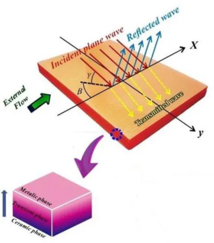
Consider a Functionally Graded (FG) infinite plate in both sides with thickness h and mass density of , as shown in Fig.1. The construction is excited by an oblique plane sound wave with two angles of incidence as and 𝛽 , in which
Figure 1: The configuration of a FG plate under excitation of a plane wave with incident angle 𝛾 and azimuthal angle 𝛽
3 Fundamental formulation:
3.1 Displacement field:
Since Hyperbolic Shear Deformation Theory (HSDT) is employed to acoustic analyze of a FG plate. Therefore, the following displacement fields are considered as (Mahi et al., 2015):
U(x, y, z) = u(x, y) − z∂w∂x+ öu(𝑧)[𝜓𝑥(𝑥, 𝑦) +𝜕𝑤𝜕𝑥] (1)
𝑉(𝑥, 𝑦, z) = 𝜈(𝑥, 𝑦) − z∂w∂x+ öí(𝑧)[𝜓𝑦(𝑥, 𝑦) +𝜕𝑤𝜕𝑦] (2)
𝑊(𝑥, 𝑦, z) = 𝑤(𝑥, 𝑦)(3)
In Eqs. (1)- (3), 𝜓𝑥 and 𝜓𝑦 present the rotations of the transverse normal in 𝑥 and 𝑦 directions, respectively. Moreover,
𝑢, 𝑣 and 𝑤 describe the displacements on the middle surface of the structure. However, 𝜑𝑢 and 𝜑𝑣show the shape functions as a combination of polynomial and hyperbolic tangent functions as below:
𝜑𝑢(𝑧) = 𝜑𝜈(𝑧) = 𝜑(𝑧) =ℎ2𝑡𝑎𝑛ℎ (2𝑧ℎ) −3𝑐𝑜𝑠ℎ42(1)(
𝑧3
3.2 Strains relationship
According to HSDT, the strains are considered as fallow (Zhou et al., 2013):
𝜀𝑥=𝜕𝑢𝜕𝑥− 𝑧𝜕𝑤𝜕𝑥+ ö(𝑧) [𝜕𝜓𝜕𝑥𝑥+𝜕
2𝑤
𝜕𝑥2] (5)
𝜀𝑦 =𝜕𝜈𝜕𝑦− 𝑧𝜕𝑤𝜕𝑦+ ö(𝑧) [𝜕𝜓𝜕𝑦𝑦+𝜕
2𝑤
𝜕𝑦2] (6)
𝜀𝑧= 0 (7)
𝛾𝑥𝑦=𝜕𝑢𝜕𝑦+𝜕𝜈𝜕𝑥− 2𝑧𝜕𝑥𝜕𝑦𝜕𝑤 + ö(𝑧) [𝜕𝜓𝜕𝑦𝑥+𝜕𝜓𝜕𝑥𝑦+ 2𝜕𝑥𝜕𝑦𝜕𝑤 ] (8)
𝛾𝑥𝑧=𝜕𝜑𝜕𝑧(𝜓𝑥+𝜕𝑤𝜕𝑥) (9)
𝛾𝑦𝑧=𝜕𝜑𝜕𝑧(𝜓𝑦+𝜕𝑤𝜕𝑦) (10)
3 Functionally Graded plate
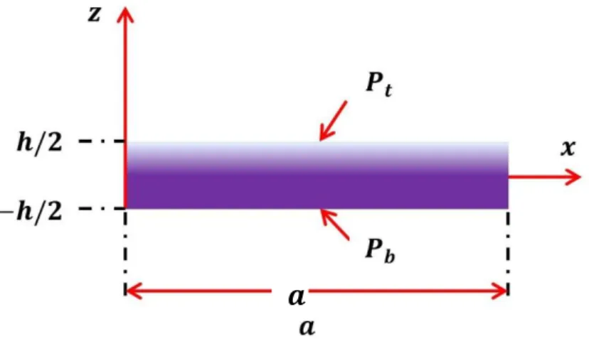
In this section, it is noteworthy that the material properties of a FG plate are formulated through thickness coordinate as below (see Fig.2):
𝑃(𝑧) = 𝑃𝑏+ (𝑃𝑡− 𝑃𝑏)𝑉(𝑧) (11)
In Eq. (11), 𝑉(𝑧) denotes to the volume fraction in the following form:
𝑉(𝑧) = (𝑧/ℎ + 1/2)𝑁, −ℎ/2 ≤ 𝑧 ≤ ℎ/2 (12)
In above equation, 𝑁 describes the power-law exponent in the interval of [0, ∞]. Moreover, 𝑃(𝑧) is one of the specifications of a FG plate including Young modulus 𝐸𝑖 , Poisson’s ratio 𝜐𝑖 and density 𝜌𝑖 in which the subscript 𝑖 can be (𝑏, 𝑡). Note that the parameters 𝑏 and 𝑡 are the material properties at the bottom and top of the structure, respectively. It is noteworthy that these material properties are continuously changed through thickness coordinate with respect to power-law component. As another consequence, 𝑝𝑡 and 𝑝𝑏 denote the material properties at top and bottom of the construction.
For the orthotropic shells the stress-strain components can be written as below (Mahi et al., 2015):
{ 𝜎𝑥
𝜎𝑦
𝜎𝑦𝑧
𝜎𝑥𝑧
𝜎𝑥𝑦}
=
{
𝑄11 𝑄12 0 0 0
𝑄21 𝑄22 0 0 0
0 0 𝑄44 0 0
0 0 0 𝑄55 0
0 0 0 0 𝑄66}{
𝜀𝑥
𝜀𝑦
𝛾𝑦𝑧
𝛾𝑥𝑧
𝛾𝑥𝑦}
(13)
In Eq. (13) 𝜎𝑖𝑗 and 𝜀𝑖𝑗 illustrate stress and strain relation in the orthotropic layer and 𝑄𝑖𝑗 present reduced stiffness constants in terms of coordinate 𝑧 , which can be obtained by following equations:
𝑄11= 𝑄22=1−𝜈𝐸(𝑧)2(𝑧) , 𝑄12= 𝑄21= 𝜈(𝑧)𝑄11, 𝑄44= 𝑄55= 𝑄66=
𝐸(𝑧)
2[1+𝜈(𝑧)] (14)
𝒬11=1−𝑣𝐸1
12𝜐21 , 𝒬22=
𝐸2
1−𝑣12𝜐21 , 𝒬12=
𝑣12𝐸2
It should be considered that these stiffness constants in Eqs. (14) and (15) are devoted to the FG and orthotropic plates, respectively. As clearly defined in Eq. (15), 𝐸𝑖in which 𝑖 = (1, 2), denotes to the modulus of elasticity, 𝐺𝑖𝑗in which 𝑖 = (1, 2) and 𝑗 = (2,3), present the modulus of rigidity. Moreover, 𝜐𝑖𝑗shows the Poisson’s ratio.
Figure 2: Schematic diagram of a FG plate.
3.4 Moments and forces resultants
By substituting Eqs. (14) and (15) into Eq. (13), the forces and moments related to FG plate are achieved as a result of integrating the stresses over the shell thicknesses as below:
(𝑁𝑥, 𝑀𝑥, 𝑀𝑥′) = ∫−ℎ/2ℎ/2(1, 𝑧, 𝜑)𝜎𝑥𝑑𝑧 (16)
(𝑁𝑦, 𝑀𝑦, 𝑀𝑦′) = ∫−ℎ/2ℎ/2(1, 𝑧, 𝜑)𝜎𝑦𝑑𝑧 (17)
(∅𝑥𝑦, 𝑀𝑥𝑦, 𝑀𝑥𝑦′ ) = ∫−ℎ/2ℎ/2(1, 𝑧, 𝜑)𝜎𝑥𝑦𝑑𝑧 (18)
(∅′𝑥𝑧, ∅𝑦𝑧′ ) = ∫−ℎ/2ℎ/2(𝜎𝑥𝑧, 𝜎𝑦𝑧)𝜕𝜑𝜕𝑧𝑑𝑧 (19)
As another consequence, the following equations are considered:
{ 𝑁𝑥
𝑁𝑦
𝑀𝑥
𝑀𝑦
𝑀𝑥′
𝑀𝑦′}
=
[
𝐴𝐴11 𝐴12 𝐵11 𝐵12 𝐵11′ 𝐵12′
12 𝐴22 𝐵12 𝐵22 𝐵12′ 𝐵22′
𝐵11 𝐵12 𝐷11 𝐷12 𝐷11′ 𝐷12′
𝐵12 𝐵22 𝐷12 𝐷22 𝐷12′ 𝐷22′
𝐵11′ 𝐵12′ 𝐷11′ 𝐷12′ 𝐷11′′ 𝐷12′′
𝐵12′ 𝐵22′ 𝐷12′ 𝐷22′ 𝐷12′′ 𝐷22′′]{
𝑢,𝑥
𝜈,𝑦
−𝑤,𝑥𝑥
−𝑤,𝑦𝑦
𝜓𝑥,𝑥+ 𝑤,𝑥𝑥
𝜓𝑦,𝑦+ 𝑤,𝑦𝑦}
(20)
{ 𝑄𝑥𝑦
𝑀𝑥𝑦
𝑀𝑥𝑦′
} = [𝐴66 𝐵66 𝐵66
′
𝐵66 𝐷66 𝐷66′
𝐵66′ 𝐷66′ 𝐷66′′
] {
𝑢,𝑦+ 𝜈,𝑥
−2𝑤,𝑥𝑦
𝜓𝑥,𝑦+ 𝜓𝑦,𝑥+ 2𝑤,𝑥𝑦
} (21)
{𝑄𝑄𝑥𝑧′
𝑦𝑧′ } = [𝐴 55
′ 0
0 𝐴44′ ] {
𝜓𝑥+ 𝑤,𝑥
𝜓𝑦+ 𝑤,𝑦}, (22)
In Eqs. (20) - (22), 𝑀𝑥′ , 𝑀𝑦′ and 𝑀𝑥𝑦′ present the higher order moments. However, some other constants including extensional stiffness 𝐴𝑖𝑗, bending stiffness 𝐷𝑖𝑗, coupling stiffness 𝐵𝑖𝑗, transverse shear stiffness 𝐴𝑖𝑗′, and also some higher-order coupling and bending rigidity including 𝐵𝑖𝑗′ , 𝐷𝑖𝑗′ and 𝐷𝑖𝑗′′ are formulated as below:
(𝐴𝑖𝑗, 𝐵𝑖𝑗, 𝐵𝑖𝑗′ ) = ∫−ℎ/2ℎ/2 𝑄𝑖𝑗(1, 𝑧, 𝜑)𝑑𝑧, ( 𝑖, 𝑗 = 1,2,6), (23)
(𝐷𝑖𝑗, 𝐷𝑖𝑗′, 𝐷𝑖𝑗′′) = ∫−ℎ/2ℎ/2 𝑄𝑖𝑗(𝑧2, 𝜑𝑧, 𝜑2)𝑑𝑧, ( 𝑖, 𝑗 = 1,2,6), (24)
𝐴𝑖𝑗′ = ∫ 𝑄𝑖𝑗(𝜕𝜑𝜕𝑧) 2
𝑑𝑧, ( 𝑖, 𝑗 = 4, 5),
ℎ/2
−ℎ/2 (25)
The moment’s inertia terms are presented in the following form:
(𝐼1, 𝐼2, 𝐼3) = ∫−ℎ/2ℎ/2 𝜌(𝑧)(1, 𝑧, 𝑧2)𝑑𝑧, (26)
(𝐼2′, 𝐼3′, 𝐼3′′) = ∫−ℎ/2ℎ/2 𝜌(𝑧)𝜑(𝑧)(1, 𝑧, 𝜑)𝑑𝑧, (27)
In Eq. (26), 𝐼1, 𝐼2 and 𝐼3demonstrate the axial, coupling and rotary inertia terms. Furthermore,
𝐼2′ , 𝐼3′ and 𝐼3′′present the higher-order terms, respectively.
3.5 Equations of motion
Since Hyperbolic Shear Deformation Theory (HSDT) is employed to achieve the results, therefore the following
equations are considered based on Hamilton’s principle as:
𝜕𝑁𝑥
𝜕𝑥 + 𝜕𝑄𝑥𝑦
𝜕𝑦 = 𝐼1 𝜕2𝑢
𝜕𝑡2+ 𝐼2′ 𝜕 2𝜓
𝑥
𝜕𝑡2 + (𝐼2′ − 𝐼2)
𝜕3𝑤
𝜕𝑥𝜕𝑡2, (28)
𝜕𝑁𝑦
𝜕𝑦 + 𝜕𝑄𝑥𝑦
𝜕𝑥 = 𝐼1 𝜕2𝜈
𝜕𝑡2+ 𝐼2′ 𝜕 2𝜓𝑦
𝜕𝑡2 + (𝐼2′− 𝐼2)
𝜕3𝑤
𝜕𝑦𝜕𝑡2, (29)
𝜕2
𝜕𝑥2(𝑀𝑥− 𝑀𝑥′) + 2
𝜕2
𝜕𝑥𝜕𝑦(𝑀𝑥𝑦− 𝑀𝑥𝑦′ ) + 𝜕2
𝜕𝑦2(𝑀𝑦− 𝑀𝑦′) +
𝜕𝑄𝑥𝑧′
𝜕𝑥 + 𝜕𝑄𝑦𝑧′
𝜕𝑦 + 𝑞 = (𝐼2− 𝐼2′) ( 𝜕3𝑢
𝜕𝑥𝜕𝑡2+
𝜕3𝜈
𝜕𝑦𝜕𝑡2) + (𝐼3′−
𝐼3′′) (𝜕
3𝜓𝑥
𝜕𝑥𝜕𝑡2+
𝜕3𝜓 𝑦
𝜕𝑦𝜕𝑡2) + 𝐼1
𝜕2𝑤
𝜕𝑡2 − (𝐼3− 2𝐼3′+ 𝐼3′′) (
𝜕4𝑤
𝜕𝑥2𝜕𝑡2+
𝜕4𝑤
𝜕𝑦2𝜕𝑡2), (30)
𝜕𝑀𝑥′
𝜕𝑥 + 𝜕𝑀𝑥𝑦′
𝜕𝑦 − 𝑄𝑥𝑧′ = 𝐼2′ 𝜕
2𝑢
𝜕𝑡2+ 𝐼3′′ 𝜕 2𝜓
𝑥
𝜕𝑡2 + (𝐼3′′− 𝐼3′)
𝜕3𝑤
𝜕𝑥𝜕𝑡2 (31)
𝜕𝑀𝑦′
𝜕𝑦 + 𝜕𝑀𝑥𝑦′
𝜕𝑥 − 𝑄𝑦𝑧′ = 𝐼2′ 𝜕
2𝜈
𝜕𝑡2+ 𝐼3′′ 𝜕 2𝜓
𝑦
𝜕𝑡2 + (𝐼3′′− 𝐼3′)
𝜕3𝑤
𝜕𝑦𝜕𝑡2, (32)
Since the structure is excited acoustically, therefore 𝑞 = (𝑃1𝐼+ 𝑃1𝑅− 𝑃1𝑇) presents the external force.
3.6 Boundary condition
In this section, it is essential to create a coupling between fluid particle and shell surface in the internal and external spaces, therefore the following equations should be taken into account (Talebitooti et al., 2018c):
𝜕(𝑝1𝐼+𝑝1𝑅)
𝜕𝑧 = −𝜌1( 𝜕2𝑤
𝜕𝑡2) (33)
𝜕(𝑝2𝑇)
𝜕𝑧 = −𝜌2 𝜕2𝑤
𝜕𝑡2 (34)
𝑝1𝐼(𝑥, 𝑦, 𝑧, 𝑡) = 𝑃0𝐼 𝑒𝑖(𝜔𝑡−𝑘1𝑥𝑥−𝑘1𝑦𝑦−𝑘1𝑧𝑧) (35)
𝑝1𝑅(𝑥, 𝑦, 𝑧, 𝑡) = 𝑝0𝑅 𝑒𝑖(𝜔𝑡−𝑘1𝑥𝑥−𝑘1𝑦𝑦−𝑘1𝑧𝑧) (36)
𝑝2𝑇(𝑥, 𝑦, 𝑧, 𝑡) = 𝑝0𝑇 𝑒𝑖(𝜔𝑡−𝑘2𝑥𝑥−𝑘2𝑦𝑦−𝑘2𝑧𝑧) (37)
Note that 𝜔 in Eqs. (35)- (37) demonstrates the angular frequency, 𝑃0 presents the amplitude of the incident wave. As another consequence, 𝑘1=𝜔
𝑐1(
1
1+𝑀1𝑠𝑖𝑛(𝛾)) illustrates the wave number which propagates in the
𝑥, 𝑦 and 𝑧 directions as follow:
𝑘1𝑥= 𝑘1𝑐𝑜𝑠 𝛾 𝑐𝑜𝑠𝛽, 𝑘1𝑦= 𝑘1𝑐𝑜𝑠 𝛾 𝑠𝑖𝑛𝛽, 𝑘1𝑧= 𝑘1𝑠𝑖𝑛𝛾 (38)
These equations in the transmitted side are presented as below:
𝑘2=𝑐𝜔2, 𝑘2𝑥= 𝑘1𝑥 , 𝑘2𝑦= 𝑘1𝑦 , 𝑘2𝑧 = √𝑘22− (𝑘2𝑥2 + 𝑘2𝑦2 ) , (39)
3.7 Solution procedure
In this section the displacements and rotation terms are considered as:
{ 𝑢𝑣
𝑤 𝜓𝑥
𝜓𝑦}
=
{ 𝑗𝑈0
𝑗𝑉0
𝑊0
𝑗𝛹𝑥0
𝑗𝛹𝑦0}
exp (𝑗(𝜔𝑡 − 𝑘1𝑥𝑥 − 𝑘1𝑦𝑦)) (40)
Now, it is well defined to insert Eqs. (35) – (37) and (40) into Eqs. (28) - (32) along with Eqs. (33) - (34). Afterwards, these seven equations are arranged in a matrix form, as below:
𝐿𝑈 = 𝐹 (41)
Where
𝑈 = [𝑈0, 𝑉0, 𝑊0, 𝛹𝑥0, 𝛹𝑦0, 𝑃0𝑅, 𝑃0𝑇]𝑇 (42)
Note that in above equation, F demonstrates the acoustic forces. However, L describes the coefficient matrix by considering that the detailed descriptions of these variables are presented in Appendix 1. Eventually, by solving Eq. (41), the unknown constants in Eq. (42) can be achieved.
4 Sound Transmission Loss:
The power transmission coefficient 𝜏 can be obtained as a ratio of transmitted power and incident power per unit area of the structure as follow (Talebitooti et al., 2018e):
𝜏 =𝐼𝑇𝑟𝑎𝑛𝑠𝑚𝑖𝑡𝑡𝑒𝑑
𝐼𝐼𝑛𝑐𝑖𝑑𝑒𝑛𝑡 =
𝜌1𝑐1
𝜌2𝑐2|
𝑃0𝑇
𝑃0𝐼|
2
(43)
Finally, STL of the construction in the logarithmic scale can be prepared as below:
5 Discussion
5.1 Validation
At the beginning of this section, it is nominated to bring forward one major frequency, known as coincidence frequency, due to equating the speed of the forced bending wave with the speed of the free bending wave based on (Talebitooti et al., 2017b) as below:
𝑓𝑐𝑜𝑖𝑛= 𝑐
2
2𝜋ℎ 𝑐𝑜𝑠2𝛾√
12𝜌(1−𝜈2)
𝐸 (45)
In Eq. (45), 𝐸 represents the modulus of elasticity, 𝜌 denotes the density and 𝜈 devotes the Poisson’s ratio, respectively. Moreover, the symbol ℎ is related to the wall thickness.
In order to provide accuracy of the present model (HSDT), the obtained results are verified with those available in literature. Therefore, the results are compared with those of (Roussos, 1984), (Abid et al., 2012) and (Howard et al., 2006). Hence, some configurations are brought up based on isotropic plate considering the same specifications at their papers.
In Fig.3, the obtained STL from present formulation (HSDT) for the special case of isotropic plate made of Aluminum according to Table 1 is compared with those of (Roussos, 1984). As it is seen, the achieved results from two theories are corroborated to each other in entire range of frequency as a consequence of presenting the result for thin shell. In fact, since isotropic thin plate is employed, therefore no discrepancies between HSDT and applied classical shell theory with Roussos can be observed. Moreover, the effects of the shear and rotation that offered by HSDT due to thin shell are not highlighted in this comparison. In addition, both theories predict the coincidence frequency at the same location.
Figure 3: STL comparison between present formulation (HSDT) and obtained results by (Roussos, 1984).
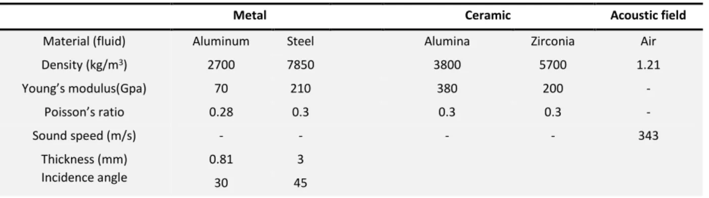
Table 1: Material and geometrical characteristics
Metal Ceramic Acoustic field
Material (fluid) Aluminum Steel Alumina Zirconia Air
Density (kg/m3) 2700 7850 3800 5700 1.21
Young’s modulus(Gpa) 70 210 380 200 -
Poisson’s ratio 0.28 0.3 0.3 0.3 -
Sound speed (m/s) - - - - 343
Thickness (mm) Incidence angle
0.81 3
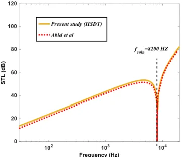
As illustrated in Fig.4, another comparison is made between present work (HSDT) and that of (Abid et al., 2012) for an isotropic thick plate made of Steel with the listed specifications in Table 1. Although, the obtained results demonstrate a good validity in entire range of frequency, a little discrepancy is observed below the coincidence frequency as a result of some numerical deviations occurred in Transfer matrix approach applied by Abid et al. Since in the present result the rotary inertia terms are extended up to higher order terms, therefore the accuracy of the current formulation would be assured.
Figure 4: The comparison of present study (HSDT) and (Abid et al., 2012).
In Fig.5, the obtained STL from the present formulation is compared with Experimental results offered by (Howard et al., 2006) for the especial case of isotropic plate made of Aluminum with the thickness of 1.5 𝑚𝑚 in which the excitation of the structure is performed by an oblique plane sound wave with the angle of 30° .As it is obvious, some discrepancies can be observed in entire range of frequency. The inspection of the results indicates that although both of structures are excited acoustically, the type of the incident wave is different which result in these variations. In fact, in the present study the excitation of the structure is done by an oblique plane sound wave whereas the field incidence acoustic condition is considered by Howard et al.
Additionally, the accuracy of the current results (HSDT) is also provided with comparing the obtained dimensionless natural frequencies from HSDT with those available in literature (Chandra et al., 2014) and (Vel et al., 2004) for the especial case of FG square plate made of Al/ZrO2, as shown in Table.2. The inspection of this table shows that not only a good agreement is observed in comparing these natural frequencies but also the obtained results are appeared to be much closer to 3D method. On the other hand, some deviations exist in the natural frequencies of First order Shear Deformation Theory as a result of applying the shear correction factor by (Chandra et al., 2014) whereas the present work is not employed this correction factor in its equations.
Table 2: Dimensionless Natural frequencies provided from HSDT in comparison with Literature 𝒂
𝒉 = 𝟓
Results Present study(HSDT) FSDT(Chandra et al., 2014)
Exact 3D(Vel et al., 2004)
N
2 0.2193 0.2189 0.2197
Power law index
3 0.2110 0.2207 0.2211
5 0.2225 0.2222 0.2225
5.2 Numerical results
In this section, some configurations are presented based on HSDT to analyze acoustic transmission of a FG plate constituted of Al-Alumina with the power-law index of 𝑁 = 1 according to Table 1. The thickness of the plate is considered to be 1 𝑚𝑚 and it is excited by an oblique plane sound wave with the angle of 30°.
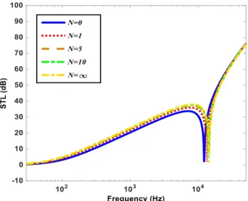
In Fig.6, the effects of various power-law distributions on STL are presented and discussed. The achieved results demonstrate that increasing the power-law exponents will enhance STL in frequency region above coincidence frequency. Besides, the coincidence frequency shifts downward in this case. Furthermore, it is essential to note that in high frequency region the trend is also similar to low frequency zone. However, when the power-law exponent goes to zero, the whole of the structure constituted of pure Aluminum, presents the minimum level of STL. On the other hand, when the power-law exponent is set to be infinite, the structure composed of pure Alumina, reveals the maximum level of STL in entire range of frequency. Moreover, the obtained results for 𝑁 = 10 (physical power) are nearly corroborated with those of 𝑁 = ∞ (theoretical concept) in frequency region above coincidence frequency.
Figure 6: The obtained STL versus to frequency with respect to different power-law distributions.
incident wave cannot penetrate the structure which results in enhancing STL. As another consequence, with increasing the thickness of the FG plate, the coincidence frequency shifts downward.
Figure 7: The influences of various FG plate thicknesses on STL curves.
As depicted in Fig.8, the effects of various isotropic and FG materials with 𝑁 = 1 on power transmission of the structure are discussed. The obtained results show that in low frequency domain, Steel as a result of having the maximum density, present the highest level of STL. Since the isotropic material includes high weight (which is addressed as a negative point for these structures) therefore employing the combination of Isotropic-FG materials such as Steel-Alumina which has the acceptable STL and less weight has the high proficiency. Besides, the location of the coincidence frequency is changed by varying this material so that AL-Alumina includes the lowest value and Al contains the highest value of coincidence frequency, respectively. It is also essential to note that at high frequency domain, Steel-Alumina, as a result of taking the upper stiffness, presents the maximum level of STL.
Figure 8: The effects of various FG and isotropic materials on STL curves
below 1600 𝐻𝑧. However, over this frequency, the trend is quite different so that STL will enhance with increasing the power-law exponent as a result of shifting the coincidence frequency downward. This event can be fulfilled due to enhancing stiffness of the FG plate.
Figure 9: The effects of various graded elasticity modulus on STL curves for different power-law distributions.
As indicated in Fig.10, the influences of graded density from 2760 (top of the plate) to 3800 (bottom of the plate) with respect to various power-law distributions on STL of the FG plate are presented and discussed. The results show that with increasing the power-law index, the value of STL is enhanced in low frequency domain. Although, coincidence frequency (𝐻𝑧) shifts forward in this case, no considerable improvement on STL can be observed in low frequency zone.
Figure 10: The effects of various FG and isotropic materials on STL curves.
In Fig.11, the effect of graded Poisson’s ratio on acoustic transmission of the FG plate is shown based on two various quantities of 0.3 and 0.28 for the bottom and top of the plate, respectively. It is easily seen that by changing this parameter, no significant deviations are appeared in entire range of frequency. By increasing awareness of this
issue, it is noteworthy that in interpreting acoustic transmission of the structure, the graded Poisson’s ratio in
Figure 11:STL provided for various poison’s ratio with respect to different power-law exponents.
Fig.12 is representative of variations in STL resulted from various 𝛽 angles, in the absence of external flow. The results show that the direct effect exists between increasing this angle and STL in frequency region below coincidence frequency which results in improving the behavior of STL. However, at high frequency zone, STL behaves in opposite way due to decreasing the wave number in 𝑥 , 𝑧 directions. As another aspect, by varying this parameter, coincidence frequency shifts upward.
Figure 12: STL provided versus to frequency with respect to different 𝛽 angles.
Figure 13: STL comparison between achieved results from FG (Al-Alumina) plate in contrast to orthotropic plate.
6 Concluding remarks
In this paper, Hyperbolic Shear Deformation Theory was considered to obtain acoustic transmission of the FG plate. Accordingly, in the first step, the equations of motion were determined. Consequently, an analytical solution was provided to solve the obtained equation besides acoustic wave equation. Moreover, the accuracy of the current formulation was prepared by bringing up some validations with previously published data. Finally, following results can be remarked:
Since Hyperbolic Shear Deformation Theory is considered, therefore the displacements are developed up to cubic order of thickness coordinate so that the effects of the main terms including coupling, bending and inertia are extended up to higher order components. Accordingly, in obtaining STL of the thick plate, the more precise results can be achieved.
The results illustrate the direct effect between power-law distribution (𝑁 ) and STL of the structure. Besides, by increasing 𝑁, coincidence frequency is reduced.
For the structure made of FG material, graded Young modulus is known as parameter which appears to be effective to produce noticeable improvement on STL in comparison with graded poison's ratio and graded density.
References
Yamanouchi, M., Koizumi, M., (1991). Functionally gradient materials. Proceeding of the first international symposium on functionally graded materials.
London, A., (1950). Transmission of reverberant sound through double walls. The journal of the acoustical society of America 22 : 270-279.
Maestrello, L., (1995). Responses of finite baffled plate to turbulent flow excitations. AIAA Journal 33: 13-19.
Clark, R. L., Frampton, K. D., (1996a). Sound transmission through an aeroelastic plate into an acoustic cavity. The Journal of the Acoustical Society of America 99: 2586-2603.
Clark, R. L., (1996b). Transmission of stochastic pressures through an aeroelastic plate into a cavity. In 37th Structure, Structural Dynamics and Materials Conference 1445.
Bhattacharya, M. C., Guy, R. W., Crocker, M. J., (1971). Coincidence effect with sound waves in a finite plate. Journal of sound and vibration 18: 157-169.
Roussos, L. A., (1984). Noise transmission loss of a rectangular plate in an infinite baffle. The Journal of the Acoustical Society of America 75: S2-S3.
Renji, K., Nair, P. S., Narayanan, S., (1997). Critical and coincidence frequencies of flat panels. Journal of Sound and Vibration 205: 19-32.
Tang, H., Zhao, X. P., Luo, C. R., (2006a). Sonic responses of an electrorheological layer with one side of grating electrodes. Journal of Physics D: Applied Physics 39(3):552
Tang, H., Luo, C. R., Zhao, X. P., (2006b). Sound transmission behavior through a sandwiched electrorheological layer. Fuhe Cailiao Xuebao/Acta Mater Compos Sinica 23: 128-132.
Xin, F. X., Lu, T. J., Chen, C. Q., (2009). External mean flow influence on noise transmission through double-leaf aeroelastic plates. AIAA J 47: 1939-1951.
Xin, F. X., Lu, T. J., (2010). Analytical modeling of sound transmission across finite aeroelastic panels in convected fluids. The Journal of the Acoustical Society of America 128: 1097-1107.
Xin, F. X., Lu, T. J., (2011). Analytical modeling of sound transmission through clamped triple-panel partition separated by enclosed air cavities. European Journal of Mechanics-A/Solids 30: 770-782.
Chandra, N., Gopal, K.N., Raja, S. (2015). Vibro-acoustic response of sandwich plates with functionally graded core. Acta Mechanica: 228(8):2775-89.
Talebitooti, R., Johari, V., Zarastvand, M. R. (2018a). Wave transmission across laminated composite plate in the subsonic flow Investigating Two-variable Refined Plate Theory. Latin American Journal of Solids and Structures, vol. 15 (5).
Liu, Y., He, C. (2016). Analytical modelling of acoustic transmission across double-wall sandwich shells: Effect of an air gap flow. Composite Structures 136: 149-161.
Daneshjou, K., Talebitooti, R., Tarkashvand, A. (2016a). Investigation on sound transmission through thick-wall cylindrical shells using 3D-theory of elasticity in the presence of external and mean air-gap flow. Journal of Vibration and Control, 24(5):975-1000.
Talebitooti, R., Zarastvand, M. R., Gheibi, M. R. (2016b). Acoustic transmission through laminated composite cylindrical shell employing Third order Shear Deformation Theory in the presence of subsonic flow. Composite Structures 157 : 95-110.
Talebitooti, R., Gohari, H. D., Zarastvand, M. R. (2017a). Multi objective optimization of sound transmission across laminated composite cylindrical shell lined with porous core investigating Non-dominated Sorting Genetic Algorithm. Aerospace Science and Technology 69: 269-280.
Talebitooti, R., Choudari Khameneh, A.M. Zarastvand, M.R., Kornokar, M. (2018b). Investigation of three-dimensional theory on sound transmission through compressed poroelastic sandwich cylindrical shell in various boundary configurations, Journal of Sandwich Structure and Matererial, 1099636217751562.
Reddy, J. N. (1984). A simple higher-order theory for laminated composite plates. Journal of applied mechanics 51: 745-752.
Mahi, A., Tounsi, A. (2015). A new hyperbolic shear deformation theory for bending and free vibration analysis of isotropic, functionally graded, sandwich and laminated composite plates. Applied Mathematical Modelling 39: 2489-2508.
Talebitooti, R., Zarastvand, M. R., Gohari, H. D. (2017b). Investigation of power transmission across laminated composite doubly curved shell in the presence of external flow considering shear deformation shallow shell theory. Journal of Vibration and Control, 24(19):4492-504.
Talebitooti, R., Zarastvand, M.R., Gohari, H.D. (2018c). The influence of boundaries on sound insulation of the multilayered aerospace poroelastic composite structure. Aerospace Science and Technology 80: 452-471.
Talebitooti, R., Zarastvand, M.R., (2018d). The effect of nature of porous material on diffuse field acoustic transmission of the sandwich aerospace composite doubly curved shell. Aerospace Science and Technology 78: 157-170.
Zhou, J., Bhaskar, A., Zhang, X. (2013). Sound transmission through a double-panel construction lined with poroelastic material in the presence of mean flow. Journal of Sound and Vibration 332: 3724-3734.
Abid, M., Abbes, M. S., Chazot, J. D., Hammemi, L., Hamdi, M. A., Haddar, M. (2012). Acoustic response of a multilayer panel with viscoelastic material. International Journal of Acoustics and Vibration 17(2):82.
Howard, C. Q., Kidner, M. R. (2006). Experimental validation of a model for the transmission loss of a plate with an array of lumped masses. In Proceedings of Acoustics :169-177.
Chandra, N., Raja, S., Gopal, K. N. (2014). Vibro-acoustic response and sound transmission loss analysis of functionally graded plates. Journal of Sound and Vibration 333: 5786-5802.
Vel, S. S., Batra, R. C. (2004). Three-dimensional exact solution for the vibration of functionally graded rectangular plates. Journal of Sound and Vibration 272: 703-730.
Appendix 1
2 2 2
11 1
11
-
x 66 1z-
1L
A k
A k
I
12 1 1 6 1
12
A k k
x zA k
6 x 1zL
k
3 3 2 2 2 2
11 1 11 1 12 1 1 6
13
B k
xB k
xB k k
x z2
B k k
6 1x 1z2
B k k
66 1x 1z 1x(
2I
2)
L
k
I
2 2 2
11 1
14
B k
xB k
66 1zI
2L
12 1 1
15 x z 66 1x 1z
L
B k k
B k k
1
21 2
L
L
2 2 2
66 1 22 1 1
22
A k
xA k
zL
I
3 3 2 2 2 2 2
22 1 22 1 12 1 1 66 1 1 12 1 1 66 1 1 1 2 2
23
B k
zB k
zB k k
x z2
B k k
x z x z2
x z z(
)
L
B k k
B k k
k
I
I
12 1 1
24 x z 66 1x 1z
L
B k k
B k k
2 2 2
66 1
25
B k
xB k
22 1zI
2L
1
31 3
L
L
2
32 3
L
L
2 2 2 2 2 2 4 4 4 4 4
1 1 3 3 3 44 1 55 1 11 1 22 1 11 1 22 1 11 1
4 2 2 2 2 2 2 2 2 2 2 2 2 2
22 1 1 12 1 1 66 1 1 12 1 1 66 1 1 12 1 1 6
3
1 1
3
6
( )( 2 ) 2 2
2 4 4 8 2 4
x z z x x z x z x
z x z x z x z x z x z x z
k k I I I A k A k D k D k D k D k D k
D k I D k k D k k D k k
L
D k k D k k D k k
3 3 2 2 2 2 2
55 1 11 1 11 1 12 1 1 66 1 1 66 1 1 1 1 3 3
4 2
3
A k
xD k
xD k
xD k k
x z2
D k k
x z2
D k
x z 1x z 1x(
)
L
k
D k k
k
I
I
3 3 2 2 2 2 2
44 1 22 1 22 1 12 1 1 66 1 1 12 1 1 66 1 1 1
5 3 3
3
A k
zD k
zD k
zD k k
x z2
D k k
x zD k k
x z2
D k k
x zk
z(
I
I
)
L
1
41 4
L
L
2
42 4
L
L
3
43 4
L
L
2 2 2
11 1 66 1 3 55
44
aa aa aa a
x z
D k
D k
L
I
A
12 1 1 6 1
45 6 1
aa aa
x z x z
D
D
L
k k
k k
1
51 5
L
L
2
52 5
L
L
3
53 5
L
L
4
54 5
2 2 2
3 66 1
55 22 1 44
aa aa aa a
x z