Point of View
THEORETICAL BASIS AND SIGNIFICANCE OF
THE VARIANCE OF DISCHARGE AS A BIDIMENSIONAL
VARIABLE FOR THE DESIGN OF LATERAL
LINES OF MICRO-IRRIGATION
Euro Roberto Detomini1; Brendan Power2; José Antônio Frizzone3*
1
USP/ESALQ Programa de PósGraduação em Engenharia Agrícola, C.P. 09 13418900 Piracicaba, SP Brasil.
2
Dept. of Primary Industries & Fisheries, PO BOX 103 - 4350 - Toowoomba - QLD, Australia. 3
USP/ESALQ - Depto. Engenharia Rural, C.P. 09 - 13418-900 - Piracicaba, SP - Brasil. *Corresponding author <[email protected]>
ABSTRACT:In order to support the theoretical basis and contribute to the improvement of educational capability issues relating to irrigation systems design, this point of view presents an alternative deduction of the variance of the discharge as a bidimensional and independent random variable. Then a subsequent brief application of an existing model is applied for statistical design of laterals in micro-irrigation. The better manufacturing precision of emitters allows lengthening a lateral for a given soil slope, although this does not necessarily mean that the statistical uniformity throughout the lateral will be more homogenous.
Key words: error theory, statistical approach, manufacturing variation
BASES TEÓRICAS E IMPORTÂNCIA DA VARIÂNCIA DA VAZÃO
COMO VARIÁVEL BIDIMENSIONAL NO DIMENSIONAMENTO
DE LINHAS LATERAIS EM MICROIRRIGAÇÃO
RESUMO:Visando a reforçar as bases teóricas e contribuir com a melhoria da capacitação educacional em assuntos relacionados a dimensionamento de sistemas de irrigação, o presente ponto de vista revela uma dedução alternativa para a variância da vazão dos emissores, variável aleatória independente bidimensional. Posteriormente apresenta breve aplicação do modelo aceito para dimensionamento de linhas laterais em sistemas de microirrigação, de acordo com a abordagem estatística. A melhor precisão na fabricação de emssores permite, para uma dada inclinação de terreno, dimensionar laterais mais longas, o que não significa necessariamente que uniformidade de emissão dessas laterais será projetada como mais homogênea.
Palavras-chave: teoria dos erros, dimensionamento estatístico, variação de fabricação
INTRODUCTION
In micro-irrigation systems, the longer the lateral pipelines are implemented in a submain unit,,the less is the final cost of the designed project, collaborating with the overall profitability of the system. In prac-tice, the hydraulic and the statistical approaches may be used to optimise the lateral length of the pipelines while maintaining the desirable uniformity of applied water. Considering the latter, the coefficient of varia-tion of the pressure head (CVHp) term appears in the
model due to the concept of discharge variance, where the source-point discharge is assumed to be suscep-tible to oscillations in both pressure head (H) and
emit-ter coefficient (K), which is inherent to the existing
variability of emitters due to manufacturing processes. Specifically, discharge variation values are assumed to follow a bivariate normal distribution without correla-tion between independent variables and hence these oscillations need to be contemplated when designing laterals. Small differences between supposedly identi-cal emitters may result in significant discharge varia-tions.
1996). It reflects the degree of precision with which the emitters are made by the manufacturer. With re-spect to average source-point discharge, one can use Taylor’s series todeduct the variance with some de-gree of difficulty or alternatively and easily via error theory. In order to support the theoretical basis and contribute to the improvement of educational capabil-ity issues relating to irrigation design, this work uses a simple algebraic manipulation used in engineering and thereby presents an alternative deduction of the vari-ance of discharge as a bidimensional variable and a brief application of the Anyoji & Wu (1987) model to statistically design laterals in micro-irrigation.
MODEL DESCRIPTION AND ALTERNATIVE DE-DUCTION
To describe the emitter discharge (q, L h–1), Keller
& Bliesner (1990) suggest the widely used power equation expressed as a function of pressure head (H,
m):
q = K . H* (1)
The variance of discharge (δq2) throughout a
lat-eral pipeline is given by:
(
)
∑
=−
⋅
=
N i m iq
q
q
N
12 2
1
δ
;∑
( )
=
⋅
=
N i qdq
N
1 2 21
δ
(2)in which qi is the discharge of the ith emitter; qm is the
mean discharge; and dq is the deviation of discharge
values (continuous variable); and N is the number of
emitters along the lateral.
Likewise, the variances of the independent variables are:
( )
∑
=⋅
=
N i KdK
N
1 2 21
δ
(3)( )
∑
=⋅
=
N i HdH
N
1 2 21
δ
(4)in which dq, dK and dH are the deviations of
dis-charge, emitter constant and pressure head, respec-tively.
The coefficient of correlation (ρ) between the ran-dom variables K and H measures the magnitude and
direction in which they linearly stretch together ahead (Moore, 1995; p.111), presented as:
(
) (
)
(
)
∑
(
)
∑
∑
= = = − ⋅ − − ⋅ − = N i m i N i m i N i m i m i H H K K H H K K 1 2 1 2 1ρ (5)
Rearranging eq. (5) in a convenient manner we have:
( ) ( )
∑
(
)
∑
(
)
∑
= = = − ⋅ − ⋅ = ⋅ N i m i N i m i N i H H K K dH dK 1 2 1 2 1 ρ (6)According to the error theory, the total derivative of eq. (1) corresponds to the total error implied when
it is used. Particularly for q, this may be described by
the chain rule:
dH H q dK K q dq ⋅ ∂ ∂ + ⋅ ∂ ∂
= (7)
where: 1 − ⋅ ⋅ = ∂ ∂ x m m x H K H q (8) x m H K q = ∂
∂ (9)
Whereas the higher-order partial differentiations are given by:
(10)
(
)
22 2
1⋅ −
− ⋅ ⋅ = ∂ ∂ x m
m x x H
K H
q (11)
Substituting eq. (7) into eq. (2):
d
∑
= ⎟ ⎠ ⎞ ⎜ ⎝ ⎛ ⋅ ∂ ∂ + ⋅ ∂ ∂ ⋅ = N i q dH H q dK K q N 1 2 2 1δ (12)
Expanding eq. (12) by taking the binomial quadratic expansion:
∑
= ⎥ ⎥ ⎦ ⎤ ⎢ ⎢ ⎣ ⎡ ⎟ ⎠ ⎞ ⎜ ⎝ ⎛ ⋅ ∂ ∂ + ⋅ ∂ ∂ ⋅ ⋅ ∂ ∂ ⋅ + ⎟ ⎠ ⎞ ⎜ ⎝ ⎛ ⋅ ∂ ∂ ⋅ = N i q dH H q dH H q dK K q dK K q N 1 2 22 1 2
δ (13) N dH H q N dH dK H q K q N dK K q N i N i N i q
∑
∑
∑
= = = ⎟ ⎠ ⎞ ⎜ ⎝ ⎛ ⋅ ∂ ∂ + ⋅ ⋅ ∂ ∂ ⋅ ∂ ∂ ⋅ + ⎟ ⎠ ⎞ ⎜ ⎝ ⎛ ⋅ ∂ ∂ = 1 2 1 1 2 2 2 δ (14)All terms involving partial differentiation on the above equation are possible to be taken out of the op-erator sum because they do not contemplate the ith
in-dices. This might be verified by rewriting eq. (8) and eq. (9). Thus:
Substituting eq. (6) into eq. (15) we have: ( ) ( ) ( ) ( ) N dH H q N H H K K H q K q N dK K q N i n i m i n i m i N i q
∑
∑
∑
∑
= = = = ⎟ ⋅ ⎠ ⎞ ⎜ ⎝ ⎛ ∂ ∂ + − ⋅ − ⋅ ⋅ ∂ ∂ ⋅ ∂ ∂ ⋅ + ⋅ ⎟ ⎠ ⎞ ⎜ ⎝ ⎛ ∂ ∂ = 1 2 2 1 2 1 2 1 2 2 2 2 ρ δ (16)Assuming that the variables K and H are
indepen-dent of each other, especially when the system pres-sure is low and the emitter material is rigid enough against deformation, r is zero and the second term of
second member vanishes in the equation above. Hence, eq. (16) reduces to:
( )
( )
N dH H q N dK K q N i N i q∑
∑
= = ⎟ ⋅ ⎠ ⎞ ⎜ ⎝ ⎛ ∂ ∂ + ⋅ ⎟ ⎠ ⎞ ⎜ ⎝ ⎛ ∂ ∂ = 1 2 2 1 2 2 2 δ (17)Substituting equations (3), (4), (8) and (9) into the equation above, we obtain:
( )
2 2(
1)
2 2 2 H x m m K x mq H δ K x H δ
δ = ⋅ + ⋅ ⋅ − ⋅ (18)
Provided that the coefficients of variation are con-sidered, this highlights that:
m q q CVq 2 δ
= (19)
m K K K CV 2 δ
= or 2
(
)
2 K m K = K ⋅CVδ
(20)m H H CVH 2 δ
= ; or
δ
H2=
(
H
m⋅
CVH
)
2; or2 2 2
m
H
CVH =δH (21)
Substituting eq. (20) and eq. (21) into eq. (18):
( )
2(
)
2(
1)
2(
)
2 2 CVH H H x K CV K H m x m m K m x mq = ⋅ ⋅ + ⋅ ⋅ ⋅ ⋅
−
δ
(22)
Reorganising the equation above in a convenient way:
(
2 2 2)
2 2 2 H K x m m
q
=
K
⋅
H
⋅
CV
+
x
⋅
CV
⋅
δ
(23)Equation (23) is going to be utilised in the coming steps, and it represents the variance of a point-source of the discharge as a bidimensional variable, that de-pends upon both emitter coefficient (K) and pressure
head (H), if clogging and temperature effects on
emit-ter discharge are neglected (i.e. design stage).
APLICABILITY OF VARIANCE OF THE BIDIMENSIONAL DISCHARGE
The expectation [E(q)] of q utilising a Taylor’s
se-ries expansion is:
⎥ ⎦ ⎤ ⎢ ⎣ ⎡ ⋅ ∂ ∂ + ⋅ ∂ ∂ ⋅ + ⋅ = 2 2 2 2 2 2 2 1 )
( x K H
m m H q K q H K q
E δ δ (24)
When all events have the same probability of oc-currence, the expectation (or expected value) equals the arithmetic average, but the second term of sec-ond member stands for the variation of discharge due to the effect of the variation of both K and H. The
expectation of q can also be called qm.
Substituting equations (10), (11) and (21), into 24 becomes:
(
)
[
1+0.5⋅ ⋅ 2⋅ −1]
⋅ ⋅
=K H x CVH x
qm m mx (25)
Substituting both eq. (25) and eq. (23) into eq. (19), the latter becomes:
(
)
(
)
[
1 0.5 2 1]
2 2 2 2 2 − ⋅ ⋅ ⋅ + ⋅ ⋅ ⋅ + ⋅ ⋅ = ⋅ x CVH x H K CVH x CV H K CVq x m m K x mm (26)
As made in this presentation for the expectation of
q [see eq. (24)], Anyoji and Wu (1987) have
demon-strated eq. (26) by using the approach of Lindley (1965) about Taylor’s Series to estimate the variance of a variable that is function of two independent vari-ables, therefore, differently from the herein presented approach, based on error theory and fully deduced for the variance. The approach of Lindley (1965) is cer-tainly and fully valid but it is more complex to deduce the variance than error theory, whereas the closed equation to deduce the expectation through Taylor’s Series can be achieved in an easier way.
The variable CVK is often referred as CVf.
Addi-tionally, CVH might be called as CVHp (coefficient of
variation of pressure on project) at the design stage, most likely to be different from the CVH of the
work-ing irrigation system. Considerwork-ing this and conveniently rearranging the equation 26, we finally have the ex-pression that, indeed, is the first step to statistically design laterals in irrigation systems:
(
1)
02 1
1 2 − 2+ 2⋅ 2 =
⎥⎦ ⎤ ⎢⎣
⎡ + ⋅ ⋅ ⋅ −
⋅ x CVHp x CVf x CVHp CVq
(27) Since CVq is a user-defined value according to a
uniformity criteria, generally not more than 0.07 (or 7%), indicating an emitter flow variation of 20% (Wu, 1997). The attributes CVf and x are known elements
from manufacturers, whereas CVHp becomes the
vari-able of interest. As it is not possible to explicitly de-rive CVHp, it must be found through any iterative
Even though Frizzone et al. (1998) have utilised eq. (26) for their calculations, which is basically the same as the one developed by Anyoji & Wu (1987) and the rearranged eq. (27), the latter is mathematically more suitable than the former in terms of programming, be-cause it expresses a typical algebraic equation to be solved in zero [i.e. f(CVHp) = 0]. Burden & Faiures
(2004) provide more details about the advantages and limitations of some of the main iterative methods in terms of facility and speed of convergence. As far as we have found, such value might be easily obtained by the root-finding algorithm of Microsoft Excel® (Tools > Goal Seek…), with no difficulty of conver-gence.
If the second term inside the brackets of the de-nominator of eq. (26) is small, as when x tends to 0.5
(i.e. working in full turbulence), the expression in the brackets [1 + 0.5 · x · CVH2 · (x – 1)] tends to 1 so
that the expectation is provided directly by the origi-nal functioorigi-nal form of q with the mean values of K
and H [see eq. (1)] and the CVq can be reduced to
the same equation as the one derived by Bralts et al. (1986).
When emitters are ideally compensating (i.e. x = 0), there is no solution for eq. (27) because this be-comes meaningless. When x = 0.5 (orifice-type emit-ters), the value of [1 + 0.5 × x × CVH2 × (x – 1)] tends
to be higher the one when 0 < x < 0.5. In other words, compensating emitters are more influenced by the value of [1 + 0.5 × x × CVH2 × (x – 1)] as a consequence
of the resulting higher CVH values. However, this is
only noted when [1 + 0.5 × x × CVH2 × (x – 1)] is
calculated after eq. (27) is solved. When x = 1, the value of [1 + 0.5 × x × CVH2 × (x – 1)] is zero.
After finding CVHp, it is used as an input value to
optimise the length of laterals according to (Anyoji & Wu, 1987):
( )
( ) ( ) ( (2) () 3) ( ) 0
1 12
1 2 3 2
1 2 2 2
2 2
= ⋅ − Δ ⋅ ⋅ + ⋅ +
+ + Δ ⋅ + ⋅ + ⋅ + ⋅
+
Hm CVHp Z Hf m m
m Z Hf m m
m
(28) in which m is the exponent with respect to discharge
in the friction equations; Hm is the mean value of
pres-sure (m) throughout the lateral – calculated by invert-ing eq. (25); Hf is the total friction loss (m)
through-out the lateral; and DZ is the level difference (m),
as-suming a negative value only in case of downhill slopes. The following equations must be substituted into eq. (28) prior to its solution:
L So Z = ⋅
Δ
100 (29)
1 3600000
1
1 ⎟⎠⋅ +
⎞ ⎜
⎝
⎛ +
⋅ ⋅
= + +
m L Se
hfe Se D q Khf Hf
m
m n m
m (30)
in which L is the length (m) of the lateral – the goal
value to be found iteratively; So is the soil slope (%),
assumed as uniform; hfe the local head losses (m –
equivalent length) at emitter insertions; Khf the
fric-tion constant; Se the emitter spacing (m); D the
inter-nal lateral diameter (m); n the adjusted empirical
co-efficient.
Analogously to eq. (27), there is no problem in solv-ing eq. (28) by ussolv-ing either of the most traditional methods (Newton-Raphson, Secant or bisection). The current approach disregards higher order terms of the Christiansen coefficient (F), in which F = 1 / (m +
1), valid for laterals contemplating a large number of emitters (i.e. N > 20). However, the exact length of lateral and consecutively the number of emitters (N)
are not known a priori (i.e. L may be very short
un-der high slope situations if at the same time Hm is low
and CVq is rigorously low), which then would require
the full equation for calculating F regardless of its
former simplification.
As N must be a non-decimal number, once a L
value is found from eq. (28), N must be truncated (for NR) preferably towards to the nearest smaller integer
value in order to obtain a little gain in terms of pres-sure throughout the lateral, which has in addition a ben-efit of preventing clogging of emitters due small par-ticles of sediments. As a consequence, a new lateral length (LR) is then recalculated:
LR = NR . Se (31)
Thus, the lateral inlet pressure (Hinl, m) and the
pressure related to each i emitter (Hi, m) may be
cal-culated, respectively, according to:
Z . Hf m
m H
Hm inl ⎟⋅ R− ⋅Δ
⎠ ⎞ ⎜ ⎝ ⎛
+ + −
= 05
2
1 (32)
(
)
[
CR]
Hf CR ZH
H R i
m i inl
i= − − − ⋅ − ⋅Δ
+1
1
1 (33)
where HfR and DZR are the recalculated DZ and Hf, in
an analogous way provided by equations (29) and (30), respectively, by replacing LR by L. Likewise eq. (28),
DZ is here is also assumed as negative for declivity
situations; CRi is the relative length, i.e. the length
be-tween the first and the ith emitter, is given by:
R i
L Se i
CR = ⋅ (34)
Consequently, the discharge (qi, L h–1) at each
emit-ter may be obtained by:
x i i K H
q = ⋅ (35)
uniformity of emission, which was modified and re-defined for design purposes, as pointed out by Bralts (1986). However, despite the existence of a number of equations to assess the uniformity (i.e. absolute emission uniformity, statistic uniformity etc.), Faveta & Botrel (2001) have compared all these equations and have shown strong correlations among them, which allows the adoption of the one that most suits the user’s need. At the design stage, the statistical unifor-mity (US, %) of water depth can be used (Juana et
al., 2004), according to (Wilcox & Swailes, 1947):
(
)
⎟ ⎟ ⎟ ⎟ ⎟
⎠ ⎞
⎜ ⎜ ⎜ ⎜ ⎜
⎝ ⎛
⋅
⎟⎟ ⎠ ⎞ ⎜⎜
⎝ ⎛
⋅ − −
⋅ = − ⋅ =
∑
∑
∑
=
= =
N
i i n
i
N
i i i
q N
q N q
CVq US
1
1 1
1 1
1 100 1
100
(36)
There are more factors affecting the uniformity of micro-irrigation than that of sprinkler irrigation besides manufacturer’s variation (Wu, 1997). These other fac-tors might be the grouping of emitters, plugging and temperature. The effect of temperature on emitter flow can be neglected when a turbulent flow emitter is used (Peng et al., 1986), whereas plugging of emitters is developed with respect to time and occurs in the form of partial plugging and complete plugging. As partial pluggings are difficult to evaluate, plugging evaluations are taken by using completely plugged emitters (Wu, 1997).
For illustrative purposes values for length were simulated from variations in the input variable CVf (2%,
4%, 6%, 8% and 10%), considering a low-pressure irrigation system designed in a 2% downhill uniform slope (So = – 2). The emitter spacing was 1 m (i.e.
coffee plantation paddock design) mounted through-out a ½” diameter (or 0.0165 m) lateral and was con-sidered grouped in one per tree; the local head pres-sure losses due to emitter insertions (hfe) was 0.1 m;
the project mean point-source discharge of 4.0 L h–1
was considered in principle, given that the emitter equa-tion qi = 1.1134 Hi0.5 was provided (orifice-type
emit-ters working under full turbulent flow, according to x
value); and the Blasius constants were assumed (Khf
= 0.00078; m = 1.75; n = 4.75). As a project
crite-rion, a relaxed CVq of 10% was considered. The rest
of variables were calculated; such as CVHp, lateral,
losses by friction, inlet head pressure and uniformity. With the results of the simulation (Table 1), the user can perform the same simulations by running the fol-lowing procedure: (i) calculate CVHp from eq. (27);
(ii) calculate Hm from eq. (23); iii) calculate L from
the combination of equations (28), (29) and (30); (iv)
calculate Hinl from eq. (32); (v) calculate Hi from the
combination of equations (31), (34), HfR through eq.
(30) and eq. (33); (vi) calculate qi (eq. 35); and
fi-nally (vii) calculate discharge statistic uniformity of design according to eq. (36).
The required inlet head pressure tend to decrease as CVf increases, and the same is verified in the
rela-tionship between Hf and Hinl (Table 1). The statistic
uniformity of discharge tends to follow CVf
increas-ing, as CVHp decreases. Interesting to note is that,
when CVf = 10%, all results increase or decrease
abruptally. From this value on (i.e. CVf > 0.1), there
was no convergence for CVHp. This CVf could be
considered a critical value, for example, for the sce-nario assumed (So = – 2, D = 0.0165 m etc.).
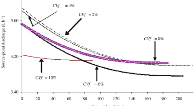
The better manufacturing of emitters implies a lower CVf value, which allows for lengthening of
lat-erals for a given soil slope, as shown in Figure 1 [the combination of the pairs i vs qi Eq. (35)], however
this does not necessarily mean that the discharge sta-tistical uniformity throughout lateral will be more ho-mogenous. It is possible to note that the flatter is the shape of the curve the shorter it is the simulated lat-eral length. Corroborating to this, a decreasing ten-dency in statistical uniformity is also highlighted as emitters are more uniformly made and hence result-ing in lower CVf values (Figure 2).
As outlined by Wu (1997), the sum of squares re-lationship shown in the second term of eq. (27) indi-cates the effect that the hydraulic design will be less significant when the emitters have high manufacturer variations. Hence, the flatter slopes obtained from the higher CVfs in Figure 1, corroborated by Figure 2,
re-inforce such relationship. Another important charac-teristic to verify in Figure 1 is not only the distribu-tion of source-point discharge values but also the lim-its of the corresponding head pressure values (Hi),
of-ten leading to quite distant values of qi from the
sug-gested mean discharge (4.0 L h–1). The designed mean
Table 1 - Main results of the performed simulation.
f V
C L Hinl Hf /Hinl US CVHp
% --- m--- --- % --- -2 218 21.76 43.04 91.18 19.52 4 214 21.35 41.69 91.55 18.37 6 205 20.45 38.68 91.55 15.90 8 187 18.94 32.43 93.98 11.88
0
1 90 13.98 5.88 99.12 2.79
CVf = Coefficient of variation in discharge due to manufacture; L = Lateral length of emitter insertion [L]; Hinl = Head pressure
source-point discharge decreased from 4.36 to 4.15 L h–1, as well as for the emitter flow relative variation
[(generally called qvar = (qmax – qmin)/qmax], going from
24.48 to 2.91%.
From the lowest (i.e. least variable) to the highest value of CVf, this simple emitter attribute alteration has
reduced the lateral length for more than one half, al-though a 2% CVf still led to an acceptable value of
micro-irrigation project uniformity (i.e. greater than 90%). The choice of a 10% CVf would lead to the
lowest pressure head at the beginning of the lateral (13.98 m), a value 64% lower than the necessary pres-sure head if a 2% CVf emitter were selected. Thus, a
10% CVf emitter would result in a more economical
system with respect to energy expense considered alone, but would be the shorter lateral line on the other hand. Wu (1997) report that when the manufacturer’s variation of selected emitters is selected to be < 10%, which is very easy to achieve, the system uniformity with CV < 20% can be achieved when the qvar is 30%.
Factors such as CVf, CVH, CVq, Hi and x should
be carefully considered when a micro-irrigation system is designed and managed in order to ensure an applica-tion of water that is as uniform as possible. However,
regular evaluation of irrigations should take place when systems are working so that they can be correctly maintained and can closely perform according to their original design (Pereira, 1999). Moreover, one can also create an optimisation model to find the best trade-off between lateral length and CVf, thereby maximising
profits; however this is not the primary goal of this work. The costs of different emitters, supposedly varying with the level of manufacturing, need to be compared as well, since it is useful to assess the profitability of an irriga-tion system by taking into account the fixed costs in-volved. It is often necessary when dealing with manu-facturing variation of a particular emitter to reinforce its applicability in practical situations of systems design. Therefore, it is always worthwhile to outline some cru-cial concepts and methodologies by bringing them in an accessible manner for educational purposes, i.e. by de-ducing eq. (27) in order to support the choice of the lowest (or even highest) CVf .
APPENDIX
List of symbols:
q - Source-point discharge [L3 t–1]
K - Coefficient in emitter discharge formula [L3-x t–1] x - Exponent of emitter discharge equation
H - Head pressure [L] ρ - Correlation δ2 - Variance
d - Deviation or differential
CVq - Coefficient of variation in discharge
CVH - Coefficient of variation of pressure heads
CVHp - Coefficient of variation of pressure heads at
design stage
CVK = CVf - Coefficient of variation in discharge due
to manufacture
E(q) - Expectation of q [L3 t–1]
L - Lateral length of emitter insertion [L]
Khf - Constant in empirical equation of head loss
m - Exponent of discharge in empirical equation of head
loss
n - Exponent of diameter in empirical equation of head
loss
N - Number of emitters
Hf - Total head losses along a working lateral [L]
ΔZ - Elevation or level difference [L]
So -Slope [L, if divided by 100; otherwise is
dimen-sionless]
Se - Emitter spacing [L]
hfe - Equivalent length of emitter [L]
D - Lateral internal diameter [L] F - Christiansen’ factor
CR - Relative length
US - Statistic uniformity of discharge
Figure 1 - Point-source discharge variation throughout laterals designed according to statistical approach.
3.40 4.20 5.00
0 20 40 60 80 100 120 140 160 180 200
Lateral length (m)
So
ur
ce
-po
in
t d
is
cha
rg
e (
L
h
-1)
CVf = 10%
CVf = 4%
CVf = 8%
CVf = 6%
CVf = 2%
List of subscripts:
H - Head pressure
i - Order of a number of series inl - inlet
K - Coefficient in emitter discharge formula
m - Mean
R - Recalculated
x - Exponent of emitter discharge equation
ACKNOWLEDGEMENT
These authors are grateful to the following Brazil-ian Institutions for their financial support: Federal De-partment of Science and Technology (MCT), National Scientific and Technological Development Council (CNPq), Sao Paulo State Scientific Foundation (FAPESP) and National Institute of Science and Tech-nology in Irrigation Engineering (INCTEI).
REFERENCES
ANYOJI, H.; WU, I.P. Statistical approach for drip lateral design.
Transactions of ASAE, v.30, p.187-192, 1987.
ASAE. ASAE standards engineering practices data. 43ed. St. Joseph: ASAE, 1996. 864p.
BRALTS, V.F. Field performance and evaluation. In: NAKAYAMA, F.S.; BUCKS, D.A. (Ed.) Trickle irrigation for crop production Amsterdam: Elsevier, 1986. p.216-240. (Development in Agricultural Engineering, 9).
BURDEN, R.L.; FAIURES, J.D. Numerical analysis. 8 ed. New York: Brooks Cole, 2004. 847p.
FAVETA, G.M.; BOTREL, T.A. Uniformity of localized irrigation systems: validation of equations. Scientia Agricola, v.58, p.427-430, 2001.
FRIZZONE, J.A.; VIEIRA, A.T.; PAZ, V.P.S.; BOTREL, T.A. Hydraulic characterisation of a drip tape. Revista Brasileira de Engenharia Agrícola e Ambiental, v.2, p.278-283, 1998. JUANA, L.; LOSADA, A.; RODRIGUEZ-SINOBAS, L.; SÁNCHEZ, R. Analytical relationships for designing rectangular drip irrigation units. Journal of Irrigation and Drainage Engineering, v.130, p.47-59, 2004.
KELLER, J.; BLIESNER, R.D. Sprinkler and trickle irrigation. New York: Von Nnostrand Reinhold, 1990. 582p.
LINDLEY, D.V. Introduction to probability and statistics (Part I). Cambridge: University Press, 1965.
MOORE, D.S. The basis practice of statistics. New York: W. H. Freeman, 1995. 680p.
PENG, G.F.; WU, I.P.; PHENE, C.J. Temperature effects on drip line hydraulics. Transactions of ASAE, v. 29, p.211-215, 1986. PEREIRA, L.S. Higher performance through combined improvements in irrigation methods and scheduling: a discussion.
Agricultural Water Management, v.40, p.153-169, 1999. WILCOX, J.C.; SWAILES, G.E. Uniformity of water distribution by some undertree orchard sprinklers. Scientific Agricultural, v.27, p.565-583, 1947.
WU, I.P. An assessment of hydraulic design of micro-irrigation systems. Agricultural Water Management, v.32, p.275-284, 1997.