*e-mail: [email protected]
1. Introduction
Recently, deformation of the short iber composites under high stress and temperature has been studied in the scientiic societies, so creep analysis become more important in various industries. Numerous researchers have investigated the steady state creep behavior using analytical and experimental methods; however, some of them have analyzed the steady state creep problems by long and time consuming methods with various considerations and assumptions.
Formerly, extensive studies have been done to determine the creep properties of the short iber composites1-4. For example, viscous low of aligned composites under tensile creep in the direction of the ibers has been studied5. Also, a research has been done for predicting the stress distribution in the unidirectional discontinuous iber composites based on the shear-lag theory and the load transfer at iber ends6.
In the recent years, the analytical methods have been introduced for analyzing nonlinear differential and ordinary equations with purpose of obtaining suitable solutions and algorithms. In addition, some analytical and experimental attempts were carried out to analyze the creep behaviors7-12. For instance, a research has been carried out on the creep behavior of pre-cracked macro-synthetic iber reinforced concrete (MSFRC) under axial tensile sustained loading12.
In this paper, new axial and radial displacement rates are semi theoretically (analytically) presented. Also, the creep behavior of the short iber composites is analytically predicted. The main objective of the study is to present a simple and comprehensive method to predict the steady state creep behavior of the reinforced materials. Unlike the creeping behavior of the matrix, the ibers have elastic behaviors in the
steady state creep of the short iber composite. For example, an important discussion is briely presented regarding the partial debonding in the creeping composites. To prevent the undesirable events, the present method can simply predict the creep rates in the second stage creep in the short iber composites. Finally, the obtained results by the analytical and inite element (FE) methods are also compared with together in order for validating the present method for the steady state creep of the short iber composites under axial tensile stress.
2. Material and Methods
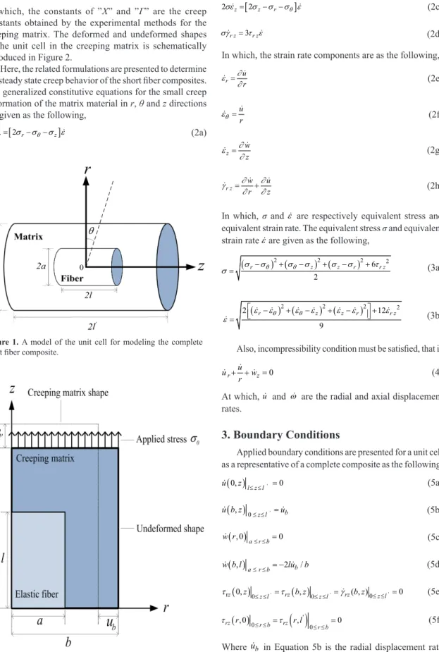
To analyze the steady state creep problem, a cylindrical unit cell model is assumed in accordance with previous researches in order for modeling a short iber composite1,2,7-11. Therefore, a unit cell of the short iber composite is a representative for a complete composite. That is,
'
( /') ( 2 / )
= = −
composite wl l unit cell ub b unit cell
ε . For instance, the
creep strain rate is the same for both the unit cell and complete composite (Figure 1). Thus, the unit cell model shown in Figure 1 is used for modeling the short iber composite.
Volume fraction and aspect ratio of the iber are respectively deined as f and s = l / a. In this research, the parameter “k” is deined as an important parameter in relation with the geometry of the unit cell (k = (l' / b)/(l /a)). An applied axial stress σ0 = σapp is uniformly applied on the end faces of the unit cell (at z = ±l'). A full and complete iber-matrix
interface is supposed, and the steady state creep behavior of the matrix is explained by an exponential law as the following in Equation 1.
On the Use of Special Functions for Analyzing the Steady State Creep
in Short Fiber Composites Semi-theoretically
Vahid Monfareda*, Saeed Daneshmandb
aDepartment of Mechanical Engineering, Zanjan Branch, Islamic Azad University, Zanjan, Iran bDepartment of Mechanical Engineering, Majlesi Branch, Islamic Azad University, Isfahan, Iran
Received: March 19, 2015; Revised: May 3, 2015
In this paper, a novel method is presented to obtain some unknowns such as displacement rate using special and well-behaved functions for short iber composites in the steady state creep by semi-theoretical method (STM). The creep behaviors are predicted in the short iber composites under tensile axial stress. Also, the regions under the partial debonding are predicted by the obtained results along with the reason of the partial debonding. The main purpose of this research is the use of the mathematical model instead of the time consuming and expensive experimental methods. On the other hand, the creep unknowns are simply obtained by the special functions rather than some complex theories. The use of sensor is one of the important applications of the present method in the regions with uniform behaviors. The obtained analytical results are validated by FEM results. Average difference between the analytical method and FEM results is about 10% approximately. Finally, good agreements are found between the obtained analytical and FEM results for predicting the creep behavior.
σ
=
exp ε Χ
Γ (1)
In which, the constants of ”X” and ”Γ” are the creep constants obtained by the experimental methods for the creeping matrix. The deformed and undeformed shapes of the unit cell in the creeping matrix is schematically introduced in Figure 2.
Here, the related formulations are presented to determine the steady state creep behavior of the short iber composites. The generalized constitutive equations for the small creep deformation of the matrix material in r, θ and z directions are given as the following,
[
]
2σεr= 2σr−σθ−σ εz (2a)
[
]
2σεθ= 2σθ−σr−σ εz (2b)
[
]
2σεz= 2σz−σr−σ εθ (2c)
3
=
σγr z τ εr z (2d)
In which, the strain rate components are as the following,
= r
u r ∂ ε
∂ (2e)
=
u
r
θ
ε (2f)
=
z w
z
∂ ε
∂ (2g)
+ = r z
w u
r z
∂ ∂
γ
∂ ∂ (2h)
In which, σ and ε are respectively equivalent stress and equivalent strain rate. The equivalent stress σ and equivalent strain rate ε are given as the following,
(
) (
2) (
2)
2 6 22
− + − + − +
= σ σθ σθ σ σ σ τ
σ r z z r r z (3a)
(
) (
2) (
2)
2 22 12
9
− + − + − +
=
εr εθ εθ εz εz εr εr z
ε (3b)
Also, incompressibility condition must be satisied, that is
0
+ + =
r z
u
u w
r (4)
At which, u and ω are the radial and axial displacement rates.
3. Boundary Conditions
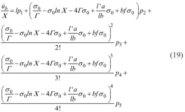
Applied boundary conditions are presented for a unit cell as a representative of a complete composite as the following,
( )
0, ≤ ≤ ' =0 l z l
u z (5a)
( )
, 0≤ ≤ '= z l b
u b z u (5b)
( )
, 0 ≤ ≤ =0 a r b
w r (5c)
( )
, ≤ ≤ = −2 / a r b b
w b l lu b (5d)
( )
'( )
' 'rz 0,z 0≤ ≤z l = rz b z, 0≤ ≤z l =rz( , )b z 0≤ ≤z l =0
τ τ γ (5e)
( )
( )
'0 0
, 0 ≤ ≤ , 0
≤ ≤
= =
rz r r b rz r l r b
τ τ (5f)
Where ub in Equation 5b is the radial displacement rate
at the outer surface of the unit cell (at r = b), see Figure 2.
Figure 1. A model of the unit cell for modeling the complete
short iber composite.
Also, the boundary conditions on the iber/matrix interface (i.e. at r = a, 0 ≤ z ≤ l) are as the following,
( )
, =0 u a z (5g)
( )
, =0 w a z (5h)
( )
, =( )
, =matrix fiber
r z a z r z a z interface
τ τ τ (5i)
( )
, =( )
, =( )
, =( )
, =matrix fiber matrix matrix
r a z r a z θ a z z a z cc
σ σ σ σ σ (5j)
In which, σcc is a constant value.
4. Theory and Calculation
The behavior of the steady state creep of silicon carbide whisker/6061 aluminum composite at 573 K has been predicted experimentally2. Here, a new mathematical and semi theoretical method (STM) is presented for analysis of the displacement rate behaviors using special functions. Also, the prediction of the creep strain rate behavior and related stresses are done analytically. Moreover, some unknowns are determined by the special functions to obtain the radial and axial displacement rates, equivalent and shear stress in steady state creep. One of the important abilities of this model is in the use of the analytical modeling instead of time consuming and expensive experimental methods.
Additionally, the present approach is very simple and straightforward for determination of the some mentioned unknowns. The results obtained by the present semi theoretical solution satisfy the equilibrium and governing, and constitutive creep equations. These analytical and semi analytical results are then validated by the inite element method (FEM). Engagingly, good agreements are found between the analytical and numerical predictions. This new approach is based on well-behaved special functions. Also, assumed displacement functions, u r z( , ) and w r z( , ), satisies the B.Cs. presented in Equations 5a-d, 5g and 5h.
With considering this section, we spotlight attention on one speciic power series expansion that satisies some special function behavior. Thus far we have been using the deinition of e, that is developed in most elementary calculus courses, namely, e=limn→∞
(
1+( )
1n)
n. Consequently for the radial displacement rate u r z( )
, , we can let( )
4(
)
0
, ,
!
=
=∑ ∈
n n
n r
u r z for r Natural Num s
n ber
λ (6)
Also, w r z
( )
, is obtained as follows,( )
4(
)
1 0 , 1 ! − = = − + ∑
n n
n
w r z r n z
n
λ
(7)
Where the coeficients of λnʹs are determined using boundary conditions presented in Equations 5a-d, 5g and 5h. In addition, shear stress behavior in the creeping matrix is analytically presented by using of Equations 1 and 2d as the following,
3 τ =
γ Γ ε Χ ε
r z r z
ln
(8)
Also, by using of Equation 1 and experimental results,2 have
0 -10.7 0.06
10 + σ =ε (9)
In general, the creep strain rate in the exponential form is more precise than the polynomial and power law forms, that is,
2 2
2 2
0 1
2 2 =
= ≅ + + +… = + + +… =
∑
n i
i i
exp a x
! !
σ σ σ Χσ Χσ
ε Χ Χ Χ
Γ Γ Γ Γ Γ (10)
Therefore, polynomial and power law functions are only a small part of the exponential function expansion. So, we can use the polynomial and power law functions instead of exponential law generally. Now, the displacement rate ub is determined by exponential form of the creeping matrix approximately. Furthermore, displacement rate is obtained without using some theories in the steady state creep in the short iber composites. Effective factor or coeficient is presented to obtain the creep displacement rate. With employing Equations 1 and 9 have,
0 -10.7 0.06
0.5 (10 + )
= − ×
b σ ξ
u b (11)
0 2 = × = −
b composite
b
u exp
Γ
ε σ
Χ ξ (12)
Where, ξ is an effective factor, that is,
0
( , , , )
∝ f k s
ξ ξ σ (13)
Then, ξ is obtain by above information, yields
0
(- × )
≅ Π
ξ exp σ (14)
So, 0 0 (- ) = × ×
Χ σ σ
Γ Π
b
u exp exp (15)
By using of the geometrical relations have,
(
)
0 0 2 - = − × × σε Χ σ
Γ Π
composite exp exp
b (16)
In which, the unknown parameter of Π is semi theoretically obtained by analytical, FEM and available experimental results as the following,
( ) '
4
= + − −
l a
ln bf
lb
Π Χ Γ (17)
So, the simpliied form of the radial displacement rate at the outer surface of the unit cell ub (at r = b) is in the following form,
0
0 0 0 0
' 4 = − − + +
σ σ Χ Γσ σ σ
Γ
b
l a l
u X exp n bf
lb (18)
0
0 0 0 0
2 0
0 0 0 0
3 0
0 0 0 0
4 0 0 5 0 1 3 0 2 4 0 ' 4 ' 4 2! ' 4 3! ' 4 4! = + − − + + − − + + − − + + − + + − + + +
b l a
ln bf lb l a ln bf lb l a ln bf lb l a ln u lp p bf l p p p b
σ σ Γσ σ σ
Χ Γ
σ σ Γσ σ σ
Γ
σ σ Γσ σ σ
Γ
σ σ Γσ σ σ
Γ Χ Χ Χ Χ (19)
The coeficients of p1, p2, p3, p4 and p5 are obtained by
semi theoretical, analytical, FEM, and experimental results using MATLAB software code (programming) and neural network method. After obtaining the weighted coeficients of p1, p2, p3, p4 andp5 by the mentioned methods, and
simpliication of the polynomial function to the power function, the following formulation is presented simply,
43 18.685
3 10−
= × σ
b
u (20)
The similar results for the parameter of Π are obtained using the other semi theoretical approaches. The behavior of the parameter of Π depends on the variations of the geometrical factors and material properties. This parameter may be obtained by determining displacement rates and available experimental results with consideration of the applied boundary conditions (Equations 5a-j).
5. Results and Discussions
To verify the present method, the SiCiber / Almatrix composite is chosen as a case study and the obtained results are compared with the FEM results. For the composite used here, SiCiber / Almatrix, the volume fraction of ibers f is 0.15 and the ibers have an aspect ratio (s) of 7.4 and k = 0.76, which are in accordance with the suggestions made in the reference.2 For comparison purpose, the inite element numerical calculations of creep behavior of this short iber composite are also performed using the inite element commercial code of ANSYS. The axisymmetry method with non-linear quadratic element is used for inite element method (FEM). This element is a higher order eight-node element and has creep modeling ability (Note that, X = exp(-24.7), Γ = 6.47)). The axisymmetry approach with nonlinear quadratic element is utilized for FEM analysis. Contour nodal solution data for analyzing the strain rate in r-direction, shear stress, and strain rate behaviors are presented by the analytical present method and FEM (Figures 3-5).
For instance, a simple and general representation of the FE model with boundary conditions and coupling conditions under tensile axial loading are shown in Figures 3a, b.
The marked region in Figure 3c shows the high possibility for occurring the partial debonding because of the high total mechanical strain in the r-direction in the mentioned
region. So, this high possibility for occurring the partial debonding should be considered in the composite design under high stress and temperature. In addition, the comparison between the obtained analytical work and inite element method (FEM) results are shown in Figures 4, 6, 7 and 8.
It is interesting that the gradients of the shear stress values at the region located at 0.75l ≤ z ≤ l, r = a + δ are very small. However, this gradient is high at the region located at 0 ≤ z ≤ 0,25l, r = a + δ. These changes in the gradients are because of the nature of the tensile steady state creep phenomenon in the short iber composites.
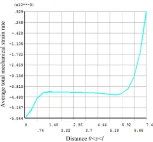
In which, δ is small enough and also positive. Moreover, the average obtained results are presented to determine the total strain rate behavior in r-direction at r = b, 0 < z < l in the creeping matrix with assumption of a=1 (Figure 5).
In Figure 5, the behavior of the average total mechanical strain rate is steady and uniform (constant value of 4.2 × 10⁻³ at 1.5 ≤ z ≤ 6). The behavior of the mentioned region at 1.5 ≤ z ≤ 6 is steady and favorable
for composite design. Also, the region is safe because, the sudden and unexpected behavior such as surprising creep rupture is not seen in the region, and the behavior is smooth and uniform. As an important application, using sensors for controlling and tracking the creep deformations in the mentioned region can be desired and be safe due to uniform behavior of the creeping matrix.
Figure 6 shows an important relation between the shear stress and shear strain rate at r = a + δ in the creeping matrix. The following formulation deines the mentioned relation between the shear stress and shear strain rate at
r = a + δ in the creeping matrix in the polynomial form as below,
14 6 12 5
11 4 10 3
9 2 8 9
2 10 2 10
5 10 8 10
5 10 10 10
− − − − − − − = × − × + × − × + × − +
rz rz rz
rz rz
rz rz
ε τ τ
τ τ
τ τ
(21)
In addition, shear strain rate behavior with respect to the normalized axial position is shown in Figures 7 and 8.
The obtained results show that shear strain rate behavior is smooth and soft at r = a + δ and r = a − δ in the creeping matrix. Therefore, these smooth and soft gradients and slopes in the curves are because of the nature of the second stage creep of the matrix in the short iber composites.
Therefore, in order for preventing the undesirable events, we can control and predict the related creep rate behaviors in the steady state creep of the short iber composite in accordance with the obtained results by present method.
Figure 3. (a) Axisymmetric model of the inite element in unit cell (b) FEM meshing (c) Contour nodal solution data to analyze the
Figure 6. The relation between shear strain rate and shear stress
at r = a + δ .
Figure 7. Shear strain rate behavior at r = a + δ .
Figure 8. Shear strain rate behavior at r = a - δ.
Table 1. Comparison between the obtained results and experimental
data2 for obtaining the radial displacement rate at the outer surface (
b u).
Composite 6061Al/15%SiC
Applied stress (MPa)
Methods
STM (Present work)
Experimental2 FEM
(Present work)
70 8.96 × 10⁻⁹ 7.58 × 10⁻⁹ 7.981 × 10⁻⁹ 86 4.19 × 10⁻⁷ 3.70 × 10⁻⁷ 3.736 × 10⁻⁷ 90 9.82 × 10⁻⁷ 6.59 × 10⁻⁷ 8.742 × 10⁻⁷ 95 2.69 × 10⁻⁶ 2.10 × 10⁻⁶ 2.411 × 10⁻⁶ 100 7.03 × 10⁻⁶ 6.59 × 10⁻⁶ 6.255 × 10⁻⁶
Figure 4. Behavior of the shear stress at r = a + δ by FEM and
STM (Analytical, present work).
Figure 5. The average obtained results for achieving total strain
rate behavior in r-direction at r = b, 0 < z < l in the creeping matrix with assumption of a=1.
6. Conclusions
According to the research, the following results can be concluded,
• The radial and axial displacement rates are determined using the well-behaved special functions by STM. Also, relation between the shear stress and shear strain rate was obtained at r = a + δ in the creeping matrix in the polynomial form by present method along with effective factor and coeficient.
• One of the advantages of the mentioned method is using of the mathematical modeling instead of time consuming and costly experimental methods, and complex methods.
References
1. Cox HL. The elasticity and strength of paper and other ibrous
materials. British Journal of Applied Physics. 1952; 3(3):72-79. http://dx.doi.org/10.1088/0508-3443/3/3/302.
2. Morimoto T, Yamaoka T, Lilholt H and Taya M. Second stage creep of silicon carbide whisker/6061 aluminum composite at 573 K. Journal of Engineering Materials and Technology. 1988; 110(2):70-76. http://dx.doi.org/10.1115/1.3226032.
3. Lee YS, Batt TJ and Liaw PK. Stress analysis of a composite material with short elastic fibre in power law creep matrix.
International Journal of Mechanical Sciences. 1990; 32(10):801-815. http://dx.doi.org/10.1016/0020-7403(90)90160-K.
4. Khadraoui F. Creep and shrinkage behavior of CFRP-reinforced
mortar. Construction & Building Materials. 2012; 28(1):282-286. http://dx.doi.org/10.1016/j.conbuildmat.2011.07.048. 5. McLean D. Viscous flow of aligned composites. Journal of
Materials Science. 1972; 7(1):98-104. http://dx.doi.org/10.1007/
BF00549556.
6. Fukuda H and Chou TW. An advanced shear-lag model applicable to discontinuous fiber composites. Journal of
Composite Materials. 1981; 15(1):79-91. http://dx.doi.
org/10.1177/002199838101500107.
7. Tapkın S, Çevik A, Uşara U and Gülşan E. Rutting prediction of asphalt mixtures modified by polypropylene fibers via repeated
creep testing by utilising genetic programming. Materials
Research. 2013; 16(2):277-292.
8. Reis JF So. and Bueno LO. Hot tensile and creep rupture data
extrapolation on 2.25Cr-1Mo steel using the CDM
penny-kachanov methodology. Materials Research. 2014; 17(2):518-526. http://dx.doi.org/10.1590/S1516-14392014005000007.
9. Costa PR Jr., Moura C No. and Wade DA. Evaluation of a 7050-TAF aluminum alloy submitted to creep age forming. Materials
Research. 2014; 17(3):603-611. http://dx.doi.org/10.1590/
S1516-14392014005000051.
10. Monfared V and Mondali M. Semi-analytically presenting the creep strain rate and quasi shear-lag model as well as finite
element method prediction of creep debonding in short fiber
composites. Materials & Design. 2014; 54:368-374. http://
dx.doi.org/10.1016/j.matdes.2013.08.040.
11. Monfared V, Daneshmand S and Monfared AH. Effects of atomic number and atomic weight on inelastic time dependent
deformations. Kovove Materialy-Metallic Materials. 2015; 53(2):85-89.
12. Babafemi AJ and Boshoff WP. Tensile creep of macro-synthetic fibre reinforced concrete (MSFRC) under uni-axial tensile
loading. Cement and Concrete Composites. 2015; 55:62-69.
http://dx.doi.org/10.1016/j.cemconcomp.2014.08.002. • At the end of the iber, the possibility of occurrence of
the partial debonding is high because of the high total mechanical strain in the r-direction in the mentioned region.
• Use of the sensors in the regions with uniform and steady strain rate is one of the important applications of the present method.