Abstract
This paper presents results of eight experimental tests carried to evaluate the mechanical performance of unconnected “W” stirrups. Reinforced concrete wide beams were tested and their characteristics were idealized to represent column strips in flat slab buildings. The main variables were: the type of shear reinforcement; the shear span to effective depth ratio (av/d); and the flexural (ρl) and shear (ρw)
reinforcement ratios. In general, both the response and the shear re-sistance of the structural elements with unconnected “W” stirrups was similar to those elements with vertical closed stirrups. Incre-ments of shear resistance of up to 84% were achieved, indicating that they have high potential for use as shear reinforcement in slab-col-umn connections.
Keywords
Reinforced concrete; Shear resistance; Shear reinforcement.
One-Way Shear Resistance of RC
Members with Unconnected Stirrups
1 INTRODUCTION
In reinforced concrete buildings, the use of flat slabs (see Figure 1a) or ribbed slabs supported on wide beams (see Figure 1b) is common if a flat flooring system is desired. Both cases are susceptible to abrupt shear failures, which can occur with low levels of cracking and displacement, as shown in Figures 1c and 1d. The use of shear reinforcement improves both ductility and ultimate resistance, but their structural performance is significantly dependent of its anchorage at their ends. In such situations, in order to improve the force transfer mechanisms, design standards recommend that the shear reinforcement such as stirrups shall extend as close as possible to the compression and tension
Maurício P. Ferreira a, * Rafael N. M. Barros a Manoel J. M. Pereira Filho a Luamim S. Tapajós a Felipe S. Quaresma a
a Faculty of Civil Engineering, Institute
of Technology, Federal University of Para, Belem, Para, Brazil.
Corresponding author: * [email protected]
http://dx.doi.org/10.1590/1679-78252872
surfaces. They also recommend that between anchored ends, each bend shall enclose a longitudinal bar. However, for flat slabs this can significantly complicate the construction process, especially if a radial arrangement distribution of the shear reinforcement is desired, as it favours clashes with the flexural rebars.
a) flat slabs c) punching failure
b) wide beams and ribbed slabs d) one-way shear failure
Figure 1: Shear failure of flat flooring systems
The use of shear reinforcement internally anchored on flexural rebars could solve this construction issue, but in terms of research is a subject where little experimental evidence is available. The main results were provided by Yamada et al. (1992), Gomes and Andrade (2000), Regan and Samadian (2001), Pilakoutas and Li (2003), Park et al. (2007), Trautwein et al. (2011) Furche (1997) Caldentey et al. (2013) and Furche and Bauermeister (2014) and involve tests on slab-column connections. Results show that in such cases, loss of anchorage can lead to premature failures due to delamination. The use of transverse welded bars or complementary reinforcement are alternatives to improve the anchorage conditions and avoid premature failures.
a) lattice girder b) prefabricated “W” stirrups
Figure 2: Prefabricated cage of “W” stirrups.
a) Cruciform arrangement: plain view b) Grid arrangement: plain view
c) Cruciform arrangement: cross section d) Grid: cross section
2 THEORETICAL BACKGROUND
2.1 Shear Reinforcement for Flat Slabs
For flat slabs, the effectiveness of a shear reinforcement is directly dependent of its capacity of absorb tensile forces and properly transfer them to concrete. Furthermore, they need to be practical for both manufacture and installation. These requirements are not easily achieved in practice, once that flat slabs are slender structural elements. Therefore, a wide variety of types of shear reinforcement has been tested and this paper summarizes some of the most important contributions in this area.
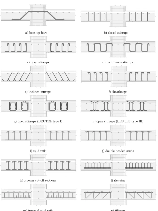
The first type of shear reinforcement proposed for flat slabs consisted of bent-up bars as shown in Figure 4a (e.g. see Graf, 1938, Elstener and Hoognestad, 1956, and Anderson, 1963), which can be highly efficient and economical when combined with other types of reinforcement, such as stirrups as shown by Broms (2000).
Various types of stirrups were also tested for flat slabs. The most common types are closed stirrups (Figure 4b) and open stirrups (Figure 4c), but there are others like continuous stirrups (Figure 4d), which were first tested by Seible et al. (1980), and inclined stirrups (Figure 4e). In general, closed and continuous stirrups are not commonly used in practice because it impairs the installations of rebars. On the other hand, although open stirrups provide more versatility to both design and con-struction, they tend to raise costs because they are laborious in terms of production and installation. Research conducted in Brazil by Melo et al. (2000), Andrade (2000) and Trautwein (2001) present results of tests on stirrups with inclination of 45º and 60º in relation to the slab plane. The latter showed excellent structural performance, but their use is restricted once they are not practical.
Chana (1993) developed preassembles of shear reinforcement (Figure 4f) which consisted of indi-vidual "u" shaped stirrups joined by welded deformed bars. The aim was to present a prefabricated cage capable of minimizing the in situ activities, reducing the labour costs. Beutel and Hegger (2000) introduced stirrups with high mechanical and constructive performance. In the first type of stirrups, shown in Figure 4g, only the upper bending rebars are enclosed by the stirrups, while in the second type (Figure 4h), both the upper and lower flexural rebars are embraced. In both cases, the structural performance observed in tests was adequate.
Stud rails (Figure 4i) and double-headed studs (Figure 4j) are industrialized types of shear rein-forcement with high control in both manufacturing and assemblage. The mechanical anchorage pro-vided by their heads results in excellent structural performance, as introduced by Dilger and Ghali (1981) and more recently reported by Ferreira et al. (2014). The shear reinforcement used by Gomes and Regan (1999) was made of I-beam cut-off sections embraced in the flexural reinforcement, like show in Figure 4k and were initially tested by Langohr et al. (1976). They were effective to prevent punching shear failures, more than doubling the load capacity observed for the reference slab without shear reinforcement.
since increments of resistance up to 70% were observed. Gomes and Andrade (2000) and Trautwein et al. (2011) tried to improve this idea and developed internal stud rails in which “u” shaped hooks were used to improve anchorage (see Figure 4m). Their results showed that the shear reinforcement was effective and that the hooks used were able to control the horizontal cracks between the shear reinforcement and the lower flexural rebars.
Figure 4n presents a recent type of punching shear reinforcement. Produced by Filigran Träger-systeme GmbH & Co and commercialized in Europe by Halfen, they were first tested by Furche (1997) and consist of prefabricated lattice girders made with three rebars chords connected by welded diagonals. One of the diagonal in intentionally vertical and the other has an inclination of 45º. They are used in in situ and precast concrete solutions to prevent punching shear and to provide support for the upper flexural reinforcement. The European Organization for Technical Assessment (EOTA) published the European Technical Assessment ETA 13/0521 (2013) that provides guidelines for the design of flat slabs with this new kind of shear reinforcement.
The positioning of the shear reinforcement is essential for their structural performance and design standards make recommendations in this regard. In case of flat slabs, they define limit values for both the position of the first reinforcement perimeter (s0) and for the spacing between radial perimeter (sr).
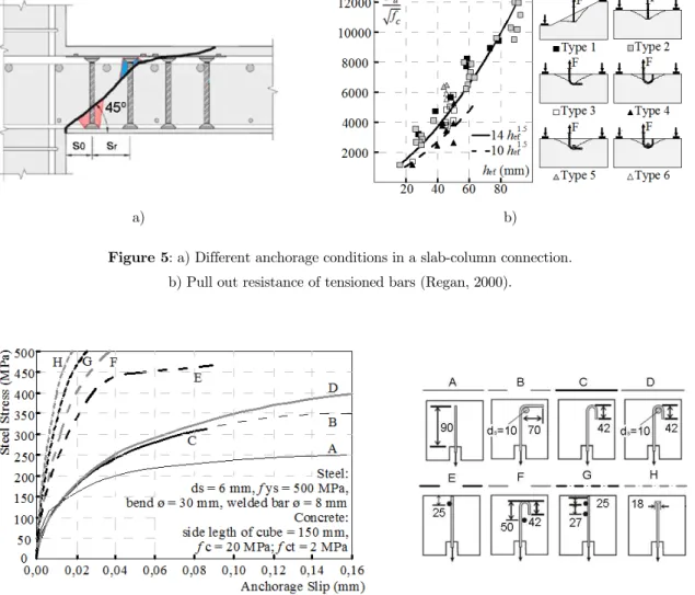
These rules try to guarantee that the reinforcement is able to control the opening of shear cracks. This directly affects the shear resistance of concrete elements for two main reasons: the opening of shear cracks tend to reduce concrete resistant mechanisms like aggregate interlock; and the spacing is going to determinate the number of bars effectively intercepted by the failure surface. Figure 5a illustrates the punching shear failure of a slab-column connection. It is possible to notice that the spacing rules seek to prevent that the shear reinforcements is placed in low anchorage areas.
Flat slabs are slender elements where the anchoring conditions of shear reinforcement are unfavour-able. According to Regan (2000), for a straight crack, the critical embedded length is only 1/4 of the effective height of the shear reinforcement. In practice, this often limits the average stress in the shear reinforcement to levels below the yield stress. Furthermore, the anchoring conditions may be different depending on the cracking degree of concrete in which the reinforcement is anchored. In Figure 5a, the lower zone is usually uncracked while in the upper area the concrete may be cracked. Cracking of concrete reduces the pull-out resistance of a rebar as reported by Eligehausen and Balogh (1995).
Regan (2000) assessed through pull-out tests the influence of the anchoring system in the response and resistance of steel anchors embedded in uncracked concrete with small embedement depths (less than 100 mm). Figure 5b summarize the experimental results. The inclination of the failure surface does not seem to affect significantly the pull-out resistance. The author also observed that 90º hooks embracing transversal reinforcement seem to be the most efficient anchorage situation.
a) bent-up bars b) closed stirrups
c) open stirrups d) continuous stirrups
e) inclined stirrups f) shearhoops
g) open stirrups (BEUTEL type I) h) open stirrups (BEUTEL type III)
i) stud rails j) double headed studs
k) I-beam cut-off sections l) riss-star
m) internal stud rails n) filigran
a) b)
Figure 5: a) Different anchorage conditions in a slab-column connection. b) Pull out resistance of tensioned bars (Regan, 2000).
Figure 6: Computational analysis of different anchorage types (Beutel and Hegger, 2002).
2.2 Methods of Calculation
Eurocode 2 (2004)
Eurocode 2 recommends Equation 1 to calculate the shear strength of elements without transverse reinforcement. This equation considers, semi-rationally, the reduction of the shear capacity due to size effect (factor k) and the favourable influence of the tension flexural reinforcement (dowel effect) through term ρl.
(
1/3)
, 3 2
0.18 (100 )
max 0.035
l c w
R c
c w
k f b d
V
k f b d
r
ìï ⋅ ⋅ ⋅ ⋅ ⋅ ⋅
ïï
= íï
⋅ ⋅ ⋅ ⋅
ïïî (1)
Where:
fc is the concrete compressive strength;
bw is the width of the cross section and d is the effective depth of the element.
200 1 2.0 k d = + £ ; 2.0 sl l w A b d
r = £
⋅ .
For elements with transverse reinforcement, Eurocode 2 considers variable strut inclination method, which assumes that the shear force is resisted by a truss model where concrete struts are equilibrated by the shear reinforcement ignoring the tensile contribution of concrete. In this case, the angle between the longitudinal axis of the beam and the concrete strut is allowed to vary between 21.8° and 45°, depending upon the applied shear force. The shear resistance in such cases is expressed in Equation 2, not higher than the maximum shear resistance defined by Equation 3.
(
)
,
,
max
0.9
cot
cot
sin
R c sw yw R cs V
A
d
f
V
ìïïïïís
⋅ ⋅q
a
⋅a
ïï ïïî
⋅ ⋅
+
=
(2)Where:
Asw is the area of shear reinforcement; s is the spacing of the stirrups;
d is the effective depth of the member;
fyw is the yield stress of the shear reinforcement;
θ is the angle of the concrete strut, 1 cot
2,5;α is the angle between the shear reinforcement bars and the longitudinal axis of the beam.
(
)
2 1 ,max
0.9
cot
cot
1
cot
w c
R
d
b
f
V
n
q
a
q
⋅ ⋅ ⋅ ⋅
⋅
+
=
+
(3)Where:
1 0.6 1
250
c
f
n = ⋅ -éêê ùúú
ë û (4)
ABNT NBR 6118 (2014)
The Brazilian standard specifies two different models to calculate the shear resistance of reinforced concrete elements. In both cases, it assumes that the shear strength VR,cs is the result of the sum of
the contributions from concrete (VR,c) and from the shear reinforcement (VR,s) as shown in Equations
5 and 9. Model I states that the shear strength VR,cs I shall be calculated assuming a fixed angle of
the concrete strut of θ = 45° and thus the concrete and steel contributions can be calculated with Equations 6 and 7, respectively. The maximum shear strength is given by Equation 8.
, V , V ,
R cs I R c I R s I
V = + (5)
, 0 0.6 ,inf
R c I c ctk w
V =V = ⋅f ⋅b ⋅d (6)
, sw 0.9 (sin cos )
R s I yw
A
V d f
s a a
æ ö÷
ç ÷
=çç ÷÷⋅ ⋅ ⋅ ⋅ +
çè ø (7)
(
)
,max .27 1 250 cot 1
c
R I c w
f
V = 0 ⋅ -æççç ö÷÷÷⋅ ⋅f b ⋅ ⋅d a+ ÷
çè ø (8)
Where:
(
)
min ; 500 MPa
yw yw
f = f is the yield stress of the stirrups;
,inf
0.7
,ctk ct m
f
=
⋅
f
is the 5% fractile tensile strength of concrete;fct,m is the mean axial tensile strength of concrete defined for concretes with
f
c£
50 MPa
as2 3 , 0.3
ct m ck
f = ⋅f .
Model II considers the effects caused by diagonal cracking, which in practice reduce the inclination of the concrete strut and, as consequence, the contribution from concrete. In this model, the Brazilian code allows the angle of the strut to vary between 30° and 45°, thus the value of VR,c II shall be
calculated in accordance with Equation 10. In this case, the concrete contribution is taken as a func-tion of the applied shear force (Vsd), which is calculated by an iterative process. The contribution
from the stirrups (VR,cs) is calculated using Equation 11 and the maximum shear resistance (VR,max II) shall be obtained using Equation 12.
, V , V ,
Rcs II R c II R s II
V = + (9)
,
,max
0 0
,max 0
R c II
R II sd
c c
R II c
, 0.9 (cotg cotg ) sin
sw
R s II yw
A
V d f
s q a a
= ⋅ ⋅ ⋅ ⋅ + ⋅ (11)
(
)
2
,max 0.54 1 sin cot cot
250
c
R II c w
f
V = ⋅æççç - ö÷÷÷f ⋅b ⋅d q⋅ a+ q ÷
çè ø (12)
ACI 318 (2014)
The model recommended by ACI assumes a fixed angle for the concrete strut of 45°. The shear resistance of members without transverse reinforcement is defined in Equation 13, where M and V are the applied bending moment and shear force in the section. In this equation,
f
c shall not exceed 8.3 MPa., 0.16 17 0.29
R c c l w c w
V d
V f b d f b d
M r
= ççèçæ ⋅ + ⋅ ⋅ ⋅ ÷ö÷÷÷ø ⋅ £ ⋅ ⋅ ⋅ (13)
In Equation 13, the term
(
V d M⋅)
can be replaced by d a/ . Alternatively, the code assumesthat for the majority of design cases the term
(
r
l⋅ ⋅
V d
)
/
M
can be taken as 0,1⋅ ⋅l fc , yielding in the simpler version presented in Equation 14., 0,17
R c c w
V = ⋅ f ⋅b ⋅d (14)
For reinforced concrete elements with transverse reinforcement, the shear resistance (VR,cs) is
calculated with Equation 15 and is defined by the sum of the contributions from concrete (VR,c) and
steel (VR,s), the last one obtained with Equation 16, where fyw is the yield stress of the stirrups,
limited to 420 MPa. The maximum shear resistance is calculated with Equation 17.
, , ,
R cs R c R s
V
=
V
+
V
(15)(
)
,
sin
cos
R s sw yw
d
V
A
f
s
a
a
æ ö÷
ç
=
ç ÷
ç ÷
÷
⋅
⋅
⋅
+
è ø
(16),max 0, 66
R c w
V = ⋅ f ⋅b ⋅d (17)
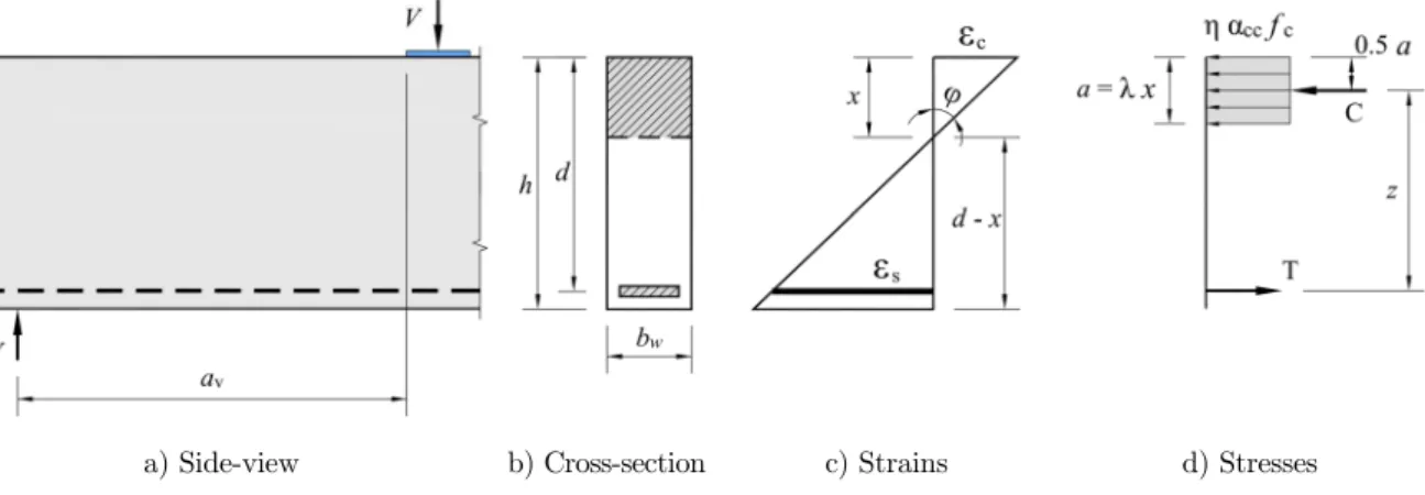
Flexural Capacity of Reinforced Concrete Members
Figure 7. Considering the recommendations presented by ABNT NBR 6118 (2014), the flexural re-sistance of reinforced concrete members can be calculated using Equations 18 to 20.
a) Side-view b) Cross-section c) Strains d) Stresses
Figure 7: Assumed strain and stresses distribution in the ultimate limit state.
sf ys
cc c w sf ys
cc c w
A f
C T f b a A f a
f b
h a
h a
⋅
= \ ⋅ ⋅ ⋅ ⋅ = ⋅ \ =
⋅ ⋅ ⋅ (18)
(
0.5
)
flex sf ys
M
=
A
⋅
f
⋅
d
-
⋅
a
(19)flex flex
v
M V
a
= (20)
Where:
η is a constant, assumed as 1 in case the breadth of the cross-section, measured parallel to the neutral axis does not decrease from this point to the more compressed edge, and 0.9 in case it does decrease; αcc is assumed as 0.85 in design cases where fc 50 MPa. In cases where long term effects of concrete
are neglected, like of short-time tests, it can be assumed as 0.95; fc is the concrete compressive strength;
bw is the width of the cross section; a is the depth of the concrete stress block; Asf is the area of flexural reinforcement;
fys is the yield stress of the flexural reinforcement; av is the shear span.
3 EXPERIMENTAL PROGRAM
The thickness and the flexural reinforcement ratio adopted in the tested wide beams are repre-sentative of the ranges observed in column strips in flat slab buildings. Also, all the specimens were designed to fail by shear. The effectiveness of the unconnected "W" stirrups was evaluated through comparison with results of tests on reference beams, which were cast without shear reinforcement, and based on tests on wide beams with closed vertical stirrups. Vertical and inclined “W” stirrups were tested. The main variable in these tests was the shear span (av). Tests were carried on
short-span (av/d 2.0) wide-beams, where arching action is significant, and slender wide-beams (av/d
2.0), where shear is transferred mainly by truss mechanisms. The other variable evaluated were the ratio of flexural (ρl) and shear (ρw) reinforcement. The name of the specimens was defined considering
the code – – C, where:
: refers to the type of shear reinforcement, where R denotes the reference specimens without shear reinforcement, C relates to specimens with closed vertical stirrups and W represents the specimens with unconnected "w" stirrups;
: refers to the shear span to effective depth (av/d) ratio and can assume the values of 2 or 4;
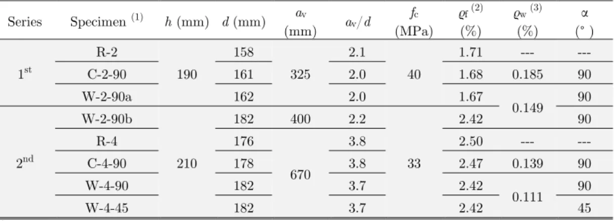
C: refers to the angle between the shear reinforcement and the longitudinal axle of the beam. 90 represents beams with vertical stirrups and 45 represent the beam with inclined stirrups. Two wide beams without shear reinforcement (R-2 and R-4) were tested and served as reference for those with closed stirrups (C-2-90 and C-4-90) and with the unconnected "w" stirrups (W-2-90a, W-2-90b, W-4-90 and W-4-45). The shear span values were defined in order to check if the perfor-mance of the unconnected “w” stirrups is influenced by the shear transfer mechanisms. Short-span beams (av/d ≈2) and slender beams (av/d≈4) were tested. Table 1 presents the main features of
these tests.
Series Specimen (1) h (mm) d (mm) av
(mm) av/d
fc
(MPa) ρf (2)
(%)
ρw (3)
(%) α (° ) 1st R-2 190 158 325 2.1 40
1.71 --- ---
C-2-90 161 2.0 1.68 0.185 90
W-2-90a 162 2.0 1.67
0.149 90
2nd
W-2-90b
210
182 400 2.2
33
2.42 90
R-4 176
670
3.8 2.50 --- ---
C-4-90 178 3.8 2.47 0.139 90
W-4-90 182 3.7 2.42
0.111 90
W-4-45 182 3.7 2.42 45
(1) the width
bw was 500 mm in all tests. (2) calculated as
,
s f w
A b ⋅d and with.
(3) calculated as ,
s w w
A b ⋅s.
Table 1: Characteristics of tested elements.
wet covering during seven days and after it, they were stored until the day of the tests at ambient weather conditions.
Samples from the steel bars used as flexural and shear reinforcement were submitted to tensile tests in accordance with the ABNT NBR 6892 (2013). Specimens with the smallest shear span (av/d
≈ 2) had 11 bars with diameter of 12.5 mm (fys = 515 MPa and εys = 2.69‰) as flexural reinforcement
(ρl≈ 1.70%). In the remaining specimens (av/d ≈ 4) the flexural reinforcement was made with 7 bars
with 20.0 mm diameter (fys = 526 MPa and εys = 2.54‰), resulting in a flexural reinforcement ratio ρl≈ 2.45 %.
In type C beams, groups of closed stirrups were combined in order to have six vertical legs in each shear reinforcement layer. They were installed embracing the flexural rebars. The “w” stirrups (type W beams) were joined in a prefabricated cage and were positioned between the upper and lower flexural rebars. Each shear reinforcement layer was formed by two vertical legs and four 45º inclined legs. The prefabricated cages were used in vertical (α = 90º) and inclined (α = 45º) arrangements. In both cases, the shear reinforcements were manufactured using 4.2 mm bars (fys = 679 MPa and εys =
4.67‰).
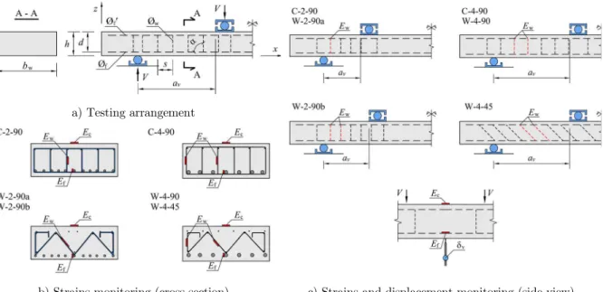
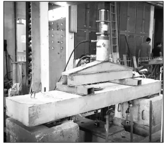
The load was applied at fixed stages, and between each loading step, short time intervals were made in order to observe the cracking pattern and measure vertical displacements and strains on concrete and on flexural and shear rebars. Figure 8 and Table 2 show details about the flexural and shear reinforcement. Strain gauges were used to measure the compressive strains in the top surfaces of the wide beams, placed in the middle of their span. In the case of the flexural and shear reinforce-ment, strains were measured by pairs of strain gauges, installed at opposite ends of diameters of the bars. Vertical displacements were measured by dial gauges placed in the middle of the beams span. Figure 8 also presents details of the instrumentation used in tests. Figure 9 show photos of different stages of the experimental program.
a) Testing arrangement
b) Strains monitoring (cross section) c) Strains and displacement monitoring (side view)
a) Beam W-2-90a before casting concrete
c) Beam W-4-90 after failure b) Test setup
Figure 9: Photos of different stages of the experimental program.
Series Specimen
Flexural Reinforcement Shear Reinforcement
øf
(mm)
fys εys
nf (1) Asf
(mm2)
øw
(mm)
fyw εyw
nw (2) Asw
(mm2)
s α
MPa ‰ MPa ‰ (mm) (°)
1st
R-2
12.5 515 2.69 11 1,350
--- --- --- --- --- --- ---
C-2-90
4.2 679 4.67
6 83
90 90
W-2-90a
4.8 (3) 67
2nd
W-2-90b
20.0 526 2.54 7 2,199
R-4 --- --- --- --- --- --- ---
C-4-90
4.2 679 4.67
6 83
120 90
W-4-90
4.8 (3) 67
W-4-45 45
(1)
nf is the number of flexural bars in tensioned zone. (2)
nw is the number of legs of shear reinforcement.
(3) “w” stirrups had 2 vertical legs and 4 legs inclined at 45º in the x-y plane. The value presented corresponds to the equivalent
number of vertical legs for wide beams with “W” stirrups.
Table 2: Characteristics of flexural and shear reinforcement.
4 RESULTS
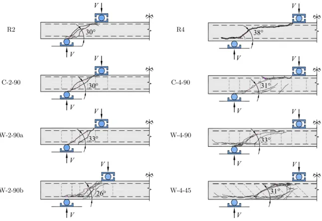
The crack morphology and progression was similar, regardless of the shear reinforcement type. All tests failed due to shear and Figure 10 presents the cracking pattern after failure. In early load stages, initial pure flexural cracks occurred and they spread towards the shear span as the load was increased. For short-span beams, the arching action was clearly observed once that the critical shear crack emerged and developed stably in an intermediate loading stage (0.5 to 0.6 of Vu). In slender beams
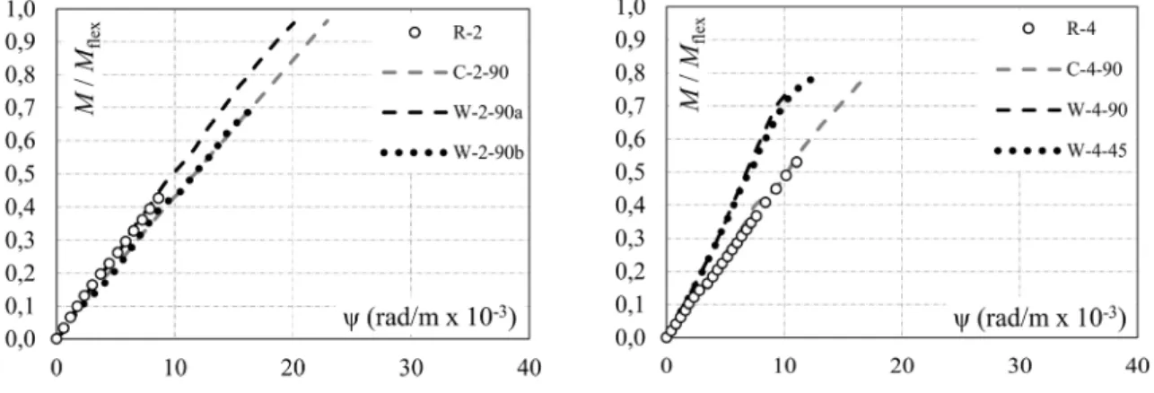
The load-deflection response was monitored as shown in Figure 7c and was affected by the type of shear reinforcement. Wide beams with “W” stirrups had a stiffer response. This may result from the fact that additional longitudinal bars are used to assist in the anchoring of the “W” stirrups, which even without appropriate detailing can contribute in the flexural response. Figure 11 presents the flexural response of the tested specimens.
In the first three tests (R2, C-2-90 and W-2-90a), only the flexural bar in the middle of the cross section was monitored. In all others, the strains in the bars in the middle and in the corner of the cross section were measured and, in such cases, results shown in Figure 12a represent average values. For short span beams, the flexural rebars of all but the reference beam (R-2) yielded. The highest flexural reinforcement ratio used in the slender beams resulted in shear failures without yielding of the bending rebars.
The flexural response of the beams, measured in terms of strains in the flexural bars, was similar in all tests, regardless of the type of shear reinforcement. However, the strains in the concrete surface were different after cracking for beams with closed stirrups and for those with unconnected “W” stirrups, as show in Figure 12b. As previous mentioned, those with “W” stirrups seem to have a stiffer response. In the case of W-2-90b the highest flexural reinforcement ratio can explain the stiffer re-sponse, but this was also observed for the other three beams with unconnected stirrups. This may be a consequence of the contribution of the extra longitudinal bars used to improve the anchorage of the “W” stirrups.
R2 R4
C-2-90 C-4-90
W-2-90a W-4-90
W-2-90b W-4-45
Figure 10: Cracking pattern after failure.
V V
V V
V V
33° 30° 30°
V
V
V
V
V
V
V
V
V
38°
31°
Figure 11: Flexural response of tested specimens.
a) Strains in the flexural reinforcement b) Strains in the concrete surface
Figure 12: Strains on flexural steel and on concrete surface.
wide beams with both closed and unconnected stirrups. For almost all cases, the maximum strains measured in the shear reinforcement were below the yield strain as shown in Figure 12a. The exception was the wide beam W-4-45, with inclined unconnected “W” stirrups, in which the strains in the inner legs were above the yield strain.
C-4-90 W-4-45
Figure 13: Strains on the shear reinforcement.
Table 3 presents the ultimate shear force (Vtest) and bending moment (Mtest) measured on tests.
It also compares the experimental results with the theoretical resistance predicted using: Models I and II from the Brazilian code NBR 6118 (VNBR-I and VNBR-II); the American design code ACI 318
(VACI); and the European design code (VEC2). It also presents results of a modified version from Model
II of NBR 6118 (VNBR-II*) done to take into account for the arching action. The Brazilian code presents
provisions for this in cases where av / d 2.0. In this proposal, this limit was increased to 2.5,
calculated as shown in Equation 21.
(
)
* 2.5
NBR II NBR II v
V - =V - ⋅ ⋅d a (21)
All specimens showed higher shear resistance than the values theoretically predicted by codes. For short-span beams, the unconnected “W” stirrups had great efficiency, providing resistance incre-ments of up to 83% if compared to the reference beam. These results are noteworthy, since that, even with four in-plane inclined legs, their performance was greater than the one from closed vertical stirrups.
Speci-men d (mm) a (mm) fc (MPa ) ρf (%) ρw (%) Vtest kN Mtest kN.m Vflex kN
Vtest /
VNBR-I
Vtest /
VNBR-II
Vtest /
VNBR-II* (3)
Vtest /
VACI
Vtest /
VEC2
R-2 158
325 40
1.71 --- 166.7 54.2 298.8 1.43 1.43 1.18 1.96 1.43
C-2-90 161 1.68 0.185 280.7 91.2 305.3 1.51 1.32 1.07 1.88 1.53
W-2-90a 162 1.67
0.149 304.0 98.8 307.4 1.75 1.56 1.25 2.21 2.06
W-2-90b 182 400
33
2.42 301.6 120.7 419.9 1.68 1.49 1.31 2.07 1.66
R-4 176
670
2.50 --- 129.9 87.0 240.3 1.14 1.14 1.14 1.51 1.01
C-4-90 178 2.47 0.139 212.8 142.6 243.8 1.24 1.10 1.10 1.53 1.13
W-4-90 182 2.42 0.111 186.7 125.1 250.7 1.14 1.03 1.03 1.42 1.20
W-4-45 182 2.42 0.158 200.5 134.3 250.7 1.10 1.02 1.02 1.34 1.30
Mean 1.37 1.26 1.14 1.74 1.42
COV 18.8% 17.2% 9.2% 18.9% 23.6%
Table 3: Test results and comparisons with design standards
Figure 14 illustrates the comparisons between the theoretical previsions and the experimental results. It shall be highlighted that no unsafe estimates were observed, indicating that the current code provisions could be used to design concrete members with unconnected “W” stirrups. From all the evaluated provisions, Eurocode 2 had the worst performance, showing the highest coefficient of variation (≈30%) and underestimating significantly the shear resistance of the wide beams with stir-rups once it ignores the contribution from concrete in such cases. ACI’s predictions were also over conservative as shown in Table 3 and Figure 14. Model II from the Brazilian code showed the best performance in terms of the evaluated code provisions.
Considering only these test results, a better correlation between the experimental results and the theoretical predictions from Model II of the Brazilian code could be achieved if the range to consider the positive contribution of the arch effect was extended to shear span to effective depth ratios of av/d < 2.5. It would be necessary to analyse a wider sample space to actually evaluate the adequacy
of this change.
5 CONCLUSIONS
This paper reviewed technical and constructive aspects of the use of shear reinforcement in slab-column connections. A new type of shear reinforcement was presented, which has the potential to be an advantageous constructive solution if compared to the shear reinforcement currently used in prac-tice. To evaluate the mechanical efficiency of this new shear reinforcement system, a series of eight experimental tests was carried in reinforced concrete wide beams, idealized to represent the column strips in flat slab buildings.
In general, both the response and shear resistance of the structural elements with unconnected “W” stirrups were similar to those elements with vertical closed stirrups. Increments of shear resistance of up to 84% were achieved with the use of the “W” stirrups, indicating that they consist of a shear reinforcement system with high potential for use in slab-column connections.
The experimental results were compared with the theoretical predictions obtained using the rec-ommendations presented by the Brazilian, American and European design standards. No unsafe shear resistance previsions were obtained, indicating that the current recommendations could be used for the design of reinforced concrete members with unconnected “W” stirrups as shear reinforcement.
Although a greater number of tests is necessary to improve their performance and to guarantee their efficiency as shear reinforcement for flat slabs, the results already available and presented in this paper are noteworthy and shall encourage more research efforts.
Acknowledgments
The authors are grateful to the Brazilian Research Funding Agencies CAPES (Higher Education Co-ordination Agency), CNPq (National Council for Scientific and Technological Development) and FAPESPA (Research Funding Agency of Para) for their support throughout this research. They also would like to thank the Applied Structural Modelling Group (NUEMA) and the Amazon Development Centre for Engineering (NDAE) for the infrastructure used in these tests.
References
ABNT NBR 5739 (2007). Concrete - Compression test of cylindrical specimens - method of test, Brazilian Technical Standards Association, Rio de Janeiro.
ABNT NBR 6118 (2014). Design of concrete structures — Procedure, Brazilian Technical Standards Association, Rio de Janeiro.
ABNT NBR 6892 (2013). Metallic materials — Tensile testing Part 1: Method of test at room temperature, Brazilian Technical Standards Association, Rio de Janeiro.
ACI 318 (2014). Building Code Requirements for Structural Concrete, American Concrete Institute, Farmington Hills, Michigan.
Anderson, J. L. (1963). Punching of Concrete Slabs with Shear Reinforcement, Royal Institute of Technology, Bulletin No. 212, KTH Stockholm, Switzerland.
Andrade, J. L. S. (2000). Estudo Experimental da Inclinação de Estribos Abertos em Lajes Cogumelo de Concreto Armado. MSc. Dissertation, Universidade de Brasília, Brasília, Brazil, 142p. (in Portuguese).
Beutel, R. and Hegger, J. (2002). The Effect of Anchorage on the Effectiveness of the Shear Reinforcement in the Punching Zone. Cement & Concrete Composite. Vol. 24, No.6, pp 539-549.
Broms, C. E. (2000). Elimination of Flat Plate Punching Failure Mode, ACI Structural Journal, V. 97, No 1, pp. 94-101.
Caldentey, A. P., Lavaselli, P. P., Peiretti, H. C., Fernández, F. A. (2013). Influence of stirrup detailing on punching shear strength of flat slabs. Engineering Structures, Vol. 49, pp 855-865.
Chana, P. S. (1993). A Prefabricated Shear Reinforcement System for Flat Slabs. Proceedings of the Institution of Civil Engineers: Structures and Buildings, Vol. 99, No.3, pp 345-358.
Dilger, W., Ghali, A., Shear Reinforcement for Concrete Slabs, Journal of Structural Engineering, ASCE, Vol. 107, 1981, pp. 2403-2420.
Eligehausen, R. and Balogh, T. (1995). Behaviour of Fasteners Loaded in Tension in Cracked Reinforced Concrete. ACI Structural Journal, Vol. 92, No 3, pp. 365-379.
Elstner, R. C. and Hognestad, E. (1956). Shearing Strength of Reinforced Concrete Slabs. Journal of the American Concrete Institute, Vol. 53, No. 7, pp. 29-58.
ETA 13/0521 (2013). Filigran FDB II Punching Shear Reinforcement, European Technical Approval, Klieken, Ger-many.
Eurocode 2 (2004). Eurocode 2: Design of Concrete Structures—Part 1-1: General Rules and Rules for Buildings. CEN, EN 1992-1-1, Brussels, Belgium.
Ferreira, M. P., Melo, G. S. S., Regan, P. E. and Vollum, R. L (2014). Punching of Reinforced Concrete Flat Slabs with Double-Headed Shear Reinforcement, ACI Structural Journal, Vol. 111, No. 2, pp 363-374.
Furche, J. (1997). Elementdecken im Durchstanzbereich von Flachdecken. Betonwerk+Fertigteiltechnik. pp. 96–104. Furche, J., Bauermeister, U., Flachdecken in Elementbauweise mit Gitterträgern: Hinweise zur Anwendung nach Eu-rocode 2, Beton- und Stahlbetonbau, Vol. 109, No. 11, 2014, pp. 783-792.
Gomes, R. B. and Andrade, M. A. S. (2000). Does a punching shear reinforcement need to embrace a flexural rein-forcement of a RC flat slab?, International Workshop on Punching Shear Capacity of RC Slabs, KTH Stockholm, June, Proceedings pp 109-117.
Gomes, R. B., and Regan, P. E. (1999). Punching Resistance of RC Flat Slabs with Shear Reinforcement. Journal of Structural Engineering, Vol. 125, No. 6, pp 684-692.
Graf, O. (1938). Versuche uber die Widerstandsfahigkeit von allseitig aufliegenden dicken Eisenbetonplatten unter Einzellasten. Deutscher Ausschus fur Eisenbeton, Heft 88, Berlin, 22p.
Langohr, P., Ghali, A., Dilger, W. Special Shear Reinforcement for Concrete Flat Plates. Journal of the American Concrete Institute, 1976, pp. 141-146.
Melo, G. S. S., Coelho, A. E. G. and Oliveira, D. R. C. (2000). RC flat slabs with inclined stirrups as shear reinforce-ment. International Workshop of Punching Shear Capacity ofRC Slabs, KTH, Stockholm, June, Proceedings pp 155-162.
Park, H. G., Ahn, K. S., Choi, K. K., Chung, L., Lattice shear reinforcement for slab-column connections, ACI Struc-tural Journal, Vol. 104, No. 3, 2007, pp. 294-303.
Pilakoutas, K., Li, X., Alternative Shear Reinforcement for Reinforced Concrete Flat Slabs, Journal of Structural Engineering, Vol. 129, No. 9, 2003, pp. 1164-1172.
Regan, P. E. (1993). Tests of connections between flat slabs and edge columns, School of Architecture and Engineering, University of Westminster, July.
Regan, P. E. and Samadian, F. (2001). Shear Reinforcement against Punching in Reinforced Concrete Flat Slabs. The Structural Engineer, Vol. 79, No. 10, pp. 24-31.
Seible, F., Ghali, A. and Dilger, W. Preassembled Shear Reinforcing Units for Flat Plates. Journal of the American Concrete Institute, Vol. 77, No. 1, 1980, pp. 28-35.
Trautwein, L. M. (2001), Punção em Lajes Cogumelo de Concreto Armado com Armadura de Cisalhamento tipo Stud Interno e Tipo Estribo Inclinado. MSc Dissertation, Universidade de Brasília, Brasília, Brazil, 185p (in Portuguese). Trautwein, L. M., Bittencourt, T. N.; Gomes, R. B.; e Bella, J. C. D. (2011). Punching Strength of Flat Slabs with Unbraced Shear Reinforcement. ACI Structural Journal, Vol. 108, No. 2, pp. 197-205.