Abstract
This work addresses an accurate and detailed axial static load de-pendence linearly elastic free vibration analysis of cylindrical helical springs based on the theory of spatially curved bars and the transfer matrix method. For a continuous system, governing equations com-prise coupled vibration modes namely transverse vibrations in two orthogonal planes, torsional and axial vibrations. The axial and shear deformation effects together with the rotatory inertia effects are all considered based on the first order shear deformation theory and their effects on the frequencies are investigated. The effects of the initial stress resultants on the frequencies are also studied. After buckling, forward-shifting phenomenon of higher frequencies is no-ticeably demonstrated. It is also revealed that a free/forced vibration analysis with an axial static load should not be performed individu-ally without checking buckling loads.
Keywords
Axial static force, helical spring, free vibration, transfer matrix, buckling load, Timoshenko beam, spatially curved bar
Axial Static Load Dependence Free Vibration Analysis of Helical
Springs Based on the Theory of Spatially Curved Bars
1 INTRODUCTION
Although, in practical applications, the springs are installed in their housing by applying initial static axial loads, the vibration of helical springs subjected to a static axial load have been paid less attention in the literature because of the difficulty and complexity in the problem. Haringx (1949) performed analytically the earliest study on the current issue by using a rod-model approximation. He studied both buckling and free vibration behavior of cylindrical helical springs with circular sections. As is well known, those formulas give acceptable results for small helix pitch angles. Wittrick (1966) inves-tigated the wave propagation in semi-infinite springs and obtained approximate solutions by taking into account the rotatory inertia and shear deformation effects. Farshad (1980) studied wave propa-gation in prestressed curved rods. By using vector approach and the transfer matrix method, Pearson (1982) presented originally the linearized disturbance equation set based on the spatial bar theory to
Vebil Yildirim a
a University of Çukurova
Department of Mechanical Engineering 01330 Adana, TURKEY
http://dx.doi.org/10.1590/1679-78253123
consider the vibration of helical springs with a static axial load. Employing Wittrick’s (1966) differ-ential equations Mottershead (1982) extended the theory to large displacements through Lagrange– Green strain equations and derived consistent geometric stiffness matrices.
Unlüsoy (1983) and Yalçın (1984) studied the free vibration of helical springs subjected to an axial static load by employing the finite element procedure. In their study the helix axis was modelled as a composition of a number of straight beam elements. Haktanır and Kıral (1992) worked on the free vibration of helical springs subjected to a static axial force with the help of the stiffness matrix formulation and straight beam elements.
Tabarrok and Xiong (1992) derived the governing equations for the buckling of spatial rods by considering perturbations about the critical state. Xiong and Tabarrok (1992) summarized a compre-hensive energy formulation for the vibration analysis of spatially curved and twisted rods under var-ious applied loads. In addition to the initial axial force, this formulation took into account the initial moments and shear forces as well as initial deformations. Based on this formulation, a spatially curved and twisted rod finite element was developed and used for several examples.
Becker and Cleghorn (1992) developed a set of dynamic, partial differential equations in canonical form for helical compression springs for just axial static force, and they solved them for fixed ends and circular cross-section by the transfer matrix method. Chassie et al. (1997) extended the work by Becker and Cleghorn (1992) for the buckling of compression springs to include the additional effect of torsion about the axis of the spring. Chassie et al. (1997) showed that both Mottershead’s (1982) and Pearson’s (1982) buckling equations do not reduce correctly to the well-known equations for simple rods. The results obtained in the Chassie et al.’s work (1997) also showed a good agreement with those from Tabarrok and Xiong (1992) and Haringx’s (1949) theory. They stated that the gov-erning equations derived were in fact a special case of the earlier and more comprehensive analysis of curved and twisted rods under load. Becker et al (2002) broadened their previous works on the buck-ling analysis for the free vibration analysis of a helical spring subjected to a static axial compressive load by incorporating inertial terms into previous buckling equations. They examined the free vibra-tion analysis numerically based on the transfer matrix method. As they stated this study represents primarily the first detailed examination of the fundamental natural frequencies of helical springs, under static axial load with clamped ends, since the pioneering work by Haringx (1949).
Yıldırım (2012) established governing equations of the helical springs with a static axial load based on the Özbek’s work (1966). Using the linearized disturbance dynamic equations derived sys-tematically in Yıldırım’s study (2012), a few functional works were conducted (Yıldırım, 2009a; İbrikçi et al. 2010). In (Yıldırım, 2009a), the numerical buckling analysis of such springs was performed based on the dynamical approach. Ibrikçi et al. (2010) proposed the use of artificial neural networks (ANN) to predict perfectly the critical buckling loads of cylindrical isotropic and homogeneous helical spring with fixed ends and with circular sections, and also having large pitch angles. Then almost perfect weight values were obtained to predict the non-dimensional buckling loads. The theory in Yıldırım’s study (2012) was extended to the free vibration of composite cylindrical helical springs under com-pression by Kacar and Yıldırım (2011, 2016). In Kacar and Yıldırım’s study (2016) the stiffness matrix method was used for the solution procedure. For a helical element with constant static axial load, the element stiffness matrix which has six degrees of freedom at each node was obtained with the help of the complementary functions method (Haktanır, 1995). Kacar and Yıldırım (2016) presented natural frequencies and buckling loads of barrel, hyperboloidal and conical unidirectional composite helical springs with circular and rectangular sections.
Kobelev (2014) studied the load dependence of transverse vibrations for helical springs by devel-oping equations, which were represented by two coupled second order differential equations. Kobelev’s (2014) method was based on the concept of an equivalent column. He derived the explicit formulas for the fundamental natural frequency of the transverse vibrations of the spring depends on the variable length of the spring. The reduction of frequency with the load was demonstrated by Kobelev (2014). In this study, similar to the Reference (Yıldırım, 2009a), it was shown that when the frequency nullifies the spring buckling occurs. It was also shown that the first vibration modes of helical springs correspond to low-frequency motions and they are strongly affected by the presence of applied axial loads.
2 GOVERNING EQUATIONS OF A SPATIAL BAR SUBJECTED TO STATIC AXIAL LOADS
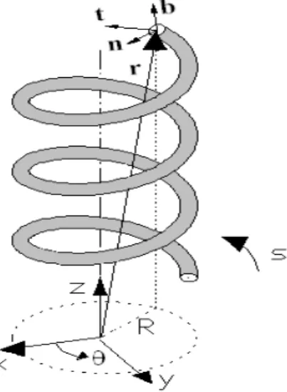
Consider a curved spatial bar having the curvilinear position coordinate s, and let t be the time. Let )
, , ( ) ,
( *
b n
t T T
T t
s * *
*
T be the internal force vector, let M*(s,t)(Mt*,Mn*,Mb*) be the internal mo-ment vector. Where *
t
T is the axial force; *
n
T and Tb* are shearing forces;
*
t
M is the torsional moment;
*
n
M and M*bare the bending moments, respectively. Let ( , )
*
t s
=(t*,n*,b*) be the rotation vec-tor, and *( , ) ( *, *, *)
U s t Ut Un Ub be the displacement vector in Frenet coordinates (t,n,b) (Figure 1). Initial internal static force and moment vectors are denoted by To(s) and Mo(s), respectively. The external distributed force and moment vectors are illustrated by p(s,t) and m(s,t), respectively.
Figure 1: Frenet trihedral.
Yıldırım (2012) derived systematically and consistently the following governing equations in a vector form for a spatial bar to study the static, buckling and vibration problems in the framework of spatial Timoshenko beam theory.
0
*
t T
U *
*
x
s T
0
*
*
M M
s
0 )
(
in
M x
s M T p p
T* * o
0 )
( )
(
in
T
M x x x
s M M t T T T m m
M * o * * o
*
(1)
ΘT b n t b n C C C GA K GA K EA 1 0 0 0 1 0 0 0 1 0 0 0 0 0 0 1 (2a) ΘM b n t b n b D D D EI EI GJ 1 0 0 0 1 0 0 0 1 1 0 0 0 1 0 0 0 1 (2b)
In the above, the undeformed cross-sectional area is denoted by A, the moments of inertia with respect to the normal and binormal axes are denoted by In and Ib, respectively. Jb is the torsional
moment of inertia, G is the shear modulus and E is the Young’s modulus. Kn and Kb represent the Timoshenko’s k-factors. For doubly symmetric cross sections, Timoshenko’s k-factors are equal to each other, Kn Kb. In equations (2) Ct is the axial rigidity, Cn and Cbare shearing rigidities, Dt
is the torsional rigidity, Dn and Db are bending rigidities. For the unit length, the inertia force and moments in Equation (1) are defined as
) (
)
( 22 t 2 2 n 2 2 b
p t U t U t U
t t n b
in ) ( )
( 2 2 2
2 2 2 2 2
2 t n b
m t k t k t k
t b b
n n t t in (3)
Here,
is the mass per unit length of the rod, kt,kn,kb are the radii of gyration with respect to the (t, n, b) axes, respectively.A L m A J k b t 2 , A I k n n 2 , A I k b b 2 (4)
3 NON-DIMENSIONAL FREE VIBRATION EQUATIONS OF A CYLINDRICAL HELICAL SPRING
SUB JECTED TO A STATIC AXIAL FORCE
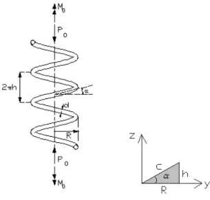
Figure 2: Geometry of a helix subjected to an axial compressive force and a torque.
Let
be the helix pitch angle, be the angular coordinate, and R=(D/2) be the radius of the cylinder. Frenet-Serret relations for cylindrical helical springs are given by (Yıldırım, 1999a)n t
ds d
n
2
c R
t b
n
ds d
t
b 2
2 c
R c
h
n b
ds d
n
2
c h
(5)
where the curvature and tortuosity are as follows
R c
c
R
2 cos cos2 constant
R c
c
h
2 sin sin cos = constant
(6)
and
c h
sin ;
c R
cos ; dscd
cos 2 cos )
tan 1 ( )
(R2 h2 1/2 R 2 1/2 R D
c
The free axial length of the helix is defined by
tan
0 n D
L (8)
In equation (8), the total number of active turns is denoted by n. Frenet components of the equivalent force-couple system at any section of the spring wire due to the initial static axial force and moment vectors will be in the following form of (Figure 2)
) cos , 0 , sin
( Po P0
o
T ) cos sin , 0 , sin cos
( PoR M0 P0R M0
o
M (9)
In order to study the free vibration analysis, the following harmonic solution may be assumed for equations (1)
t s t
s, ) ( )sin
( U
U*
t s t
s, ) ( )sin
( * t s t
s, ) ( )sin
( T
T*
t s t
s, ) ( )sin
( M
M*
(10)
without external loads, p(s,t)=0 and m(s,t)=0. Where
(rad/s) is the circular frequency. Substitut-ing equation (10) into equation (1), employSubstitut-ing Frenet-Serret relations given in equation (5), consid-ering dscd for helical elements, and then using equation (9), a set of twelve linear differentialscalar equations in Frenet trihedral, which govern the free vibration of a cylindrical helical springs subjected to a static axial load, are achieved as follows (Yıldırım, 2012).
t n t T EA U c R d
dU 1
(11a)
n n b b t n T GA cK c U c h U c R d dU
(11b)
b b n n b T GA cK c U c h d
dU
(11c)
t b n t M GJ c c R d d
(11d)
n n b t n M EI c c h c R d
d
(11e)
b b n b M EI c c h d
d
(11f)
t n
n o n
t M c U
EI cP T c R d
dT cos 2
n b b o t b o b t
n M c U
EI cP M GJ cP T c h T c R d
dT cos sin 2
(11h)
b n
n o n
b M c U
EI cP T c h d
dT sin 2
(11i)
t b n n o n o n t A J c M EI M R P c c R T GA cP K d
dM
cos ( ( sin 0cos )) 2
(11j)
n n b b o t b o b o b t o n A I c M EI M R P c c h M GJ M R P c c R T GA cP K c T EA cP d dM 2 0 0 ) ) sin cos ( ( ) ) cos sin ( ( ) sin ( cos
(11k)
b b n n o n o n b A I c M EI M R P c c h T c GA cP K d dM
0 ) 2
) sin cos ( ( ) sin (
(11l)
These linear equations given above have constant coefficients and valid for isotropic and homo-geneous cylindrical helical springs with uniform sections having double symmetry axes. The free vi-bration equations presented by Becker et al. (2002) coincide with the equations presented above in the absence of the first terms of Equations (11j), (11k) and (11l). The first terms of Equations (11j), (11k) and (11l) represent the shear deformation effects of the static axial load (Yıldırım, 2012). Equa-tions (11) may be expressed in a matrix notation as
) ( ) ( DS S d d (12)
where the state vector is given by
Tb n t b n t b n t b n
t U U T T T M M M
U
) (
S (13)
and D(,,Po,Mo) is the dynamic differential matrix. In the present study Equations (11) are put in a non-dimensional form by using the followings
n
n EI
c EI
Ac4 2 4
2
2
(15)
Taking Mo 0 and using Equations (14) and (15), elements of the dimensionless differential
matrix to be used in the present study for the free vibration analysis of the spring under a static axial force can be attained.
4 DETERMINATION OF THE GLOBAL TIP DEFLECTION OF THE SPRING UNDER A STATIC
FORCE
In a true free vibration formulation of helical springs it is necessary to implement the true deflected configuration of the spring due to the applied static axial force. Otherwise the numerical free vibration studies cannot give satisfactory results according to the specifications of the helix. So a general for-mulation of the static deflection under an axial force is required for both static and dynamic analyses. It may be noted that this is also achieved by a numerical analysis.
Even today the helical spring formulas derived in 1960s still continue to be used in the spring design. These formulas are used in special conditions/sections and do not consider the whole simul-taneous effect of the stress resultants such as axial and shearing forces, bending and torsional moments on the deformations. So they cannot called global. The popular deflection formula for closed coiled springs, 10, proposed by Wahl (1963) is given by
4 3 4
3 8
64
Gd nP D Gd
nPR
(16)
This formula may be used for open coiled helices, 10, by introducing an additional factor of
cos as follows
4 3cos
64
Gd
PnR
(17)
Both Equations (16) and (17) account for just the effect of the torsional moment on the tip deflection. However, it is obvious from Equation (9) that when even a single static axial force acts on the center of the helix then the four different types stress resultants such as an axial force, a shearing force, a bending moment and a torsional moment appear at the center of the cross-section of the helix wire. One may readily reach the consequence that there must be contributions of all the remaining stress resultants omitted in the literature on the global tip deflection of the spring.
Under a static axial force, for the determination of the vertical tip deflection of cylindrical helical compression springs with any closed section having double symmetry axes the following equation is proposed by Yıldırım (2012, 2016) and Haktanır (1994).
b
C R
Pn
2 cos
t
C R
Pn sintan
2
b
D R
Pn sintan
2 3
t
D R
Pn cos
2 3
Definitions of the cross sectional rigidities in Equation (18) are given in Equation (2). In the above equation, first term represents the effect of the shearing force, the second term is the effect of the axial force, the third term corresponds to the effect of bending moment and finally the last term is the effect of the torsional moment. Equation (18) implies that even for springs having very small angles there is a contribution of each stress resultants on the total deflection.
While Equation (18), which was obtained based on the Castigliano’s first theorem (Haktanır, 1994) , is valid for helical springs having doubly symmetric cross-sections such as solid circle, square, rectangle, ellipse, and hollow circle etc., both Equations (16) and (17) are valid for just solid circular cross sections having the following properties.
⁄ ; 2 ; A (19)
From the last term of Equation (18), Equation (17) is effortlessly obtained as follows
32 cos 2
4 3
d G
R Pn
64 34cos
Gd
PnR
(20)
It is very clear that Equation (16) is a special case of Equation (17) with cos 1. For closed-coiled springs, the effects of both the shearing force and torsional moment become leading whereas the effects of both the axial force and bending moment gain a gradually increasing impact on open coiled springs. Wahl (1963) also offered the following formula to consider both the shearing force and torsional moment effects on the axial tip deflection.
=8 0. (21)
This equation is also achieved by Equation (18)with C D/d 2R/d, cos1, and sin 0.
b
C R Pn
2
t
D R
Pn 3
2
4 2 2
2
d G
K Cd
Pn b
+ 4
3
) 2 ( 64
Gd Cd Pn
Gd
CPnKb
4
Gd Pn C3
8 8 ( 2 0.5 )
b
K C
Gd
CPn
(22)
When Kb1, Wahl’s (1963) corrected formula concurs with the present closed coil formulas in
which 0. After a quick inspection for 040o, it may be revealed that the maximum effect of the axial force is around 1% and of shearing force is around 6%. For large helix angles, while the effect of the torsional moment on the tip deflection decreases to around 65%, the effect of the bending moment increases to around 35%. Consequently, the computation truly of the tip deflection of the spring under static axial load is one of the crucial step of the vibration analysis of such springs. It may be noted that those effects gain considerably importance for especially non-circular cross-sections.
5 NUMERICAL DETERMINATION OF THE OVERALL TRANSFER MATRIX CONSISTING OF A
SINGLE HELICAL ELEMENT
As stated above, in the present study, the equations solved numerically based on the transfer matrix method with an effective numerical algorithm previously offered by the author (Yıldırım, 1996). This algorithm allows to model the whole continuous system by a single helical element without confronting any numerical difficulty and any numerical instability even if the effect of the static axial load is considered. Since it corresponds to the analytical series solution of the governing equation, the nu-merical results are assumed to be exact. In this section the transfer matrix method and the nunu-merical algorithm for the determination of the element transfer matrix will be described briefly below.
In the transfer matrix method, the solution to Equation (12) is given by Pestel and Leckie (1963) as follows
) 0 ( ) , , ( )
( F 0 S
S P (23)
where S(0) is the state vector at section 0 and F(
) is the overall transfer matrix. Solution ofEquation (23) is applicable for the helix having either varying or constant cross-sections. The transfer matrix also satisfies the following differential equation in all cases.
) ( )
(
DF
F
d d
(24)
with the initial conditions
F(0)=I (25)
where I is the unit matrix. Numerical computation of the overall transfer matrix is a crucial step in the transfer matrix method. If it is obtained in an accurate manner, then the results should be ac-ceptable as accurate. The analytical solution of the overall transfer matrix in (25) for constant cross-sections is (Pestel and Leckie, 1963).
. ... !
3 ! 2 )
( I D 2D2 3D3
F eD (26)
This solution is generally preferred in the literature due to its simplicity (Pearson, 1982; Becker et al., 2002). However, it is not possible numerically to take enough terms in the exact solution of Equation (26). So this leads to consider lots of helical elements to form the whole helix axis. In this case the element transfer matrix is computed for each division. A proper successive multiplication of the element transfer matrices renders the overall transfer matrix (Pestel and Leckie, 1963).
k k k
D
F( ) ( )
11 0
(27)where k( ) are functions of scalar infinite series in . Utilization of each term of the series k( ) of Equation (27) corresponds to twelve terms in (26). The number of terms taken from the infinite series k( ) determines the accuracy of the solution. In the present study, 1000 terms are taken in each k( ) series of Equation (27) for each to calculate the overall transfer matrix. This number of terms corresponds to the 12000 terms in Equation (27). The number of terms can be increased without any trouble to increase the accuracy of solution in the numerical algorithm previ-ously developed by the author (Yıldırım, 1996). Letting m be the total number of terms to be taken in Equation (27), each series may be put in the following form of
) ( 1 ) 2 ( 1 ) 1 ( 1 ) 0 ( 1
1()1T T T ...T m ) ( 2 ) 2 ( 2 ) 1 ( 2 ) 0 ( 2
2()T T T ...T m ) ( 3 ) 2 ( 3 ) 1 ( 3 ) 0 ( 3 2
3()2! T T T ...T m
) ( 4 ) 2 ( 4 ) 1 ( 4 ) 0 ( 4 3
4()3! T T T ...T m
) ( 11 ) 2 ( 11 ) 1 ( 11 ) 0 ( 11 10
11()10!T T T ...T m
) ( 12 ) 2 ( 12 ) 1 ( 12 ) 0 ( 12 11
12()11!T T T ...T m
(28)
where each element (i) k
T in series may be computed from the previous element (i1) k T . } { ) 2 12 )( 2 11
( 11( 1) 6 2( 11)
2 )
( 1
2 k kn
n n
k T q T
n n
T
k 0,,12,..,5
} { ) 2 13 )( 2 12
( 12( 1) 7 2( 12)
2 )
(
2 k kn
n n
k T q T
n n
T
k ,12,3,..,6
n ,12,3,..,m
(29)
where
i
i p
q 2 and p2i10 for i=1,2,..,6 (30)
and for k0 for any i, Tk(i) becomes zero. The coefficients of the characteristic determinant of the differential matrix, DI , are denoted by pi. The first terms of Tk(i) are defined as follows
k
k q
T 6
12 ) 0 (
1
2 12!
k0,,12,..,5
k
k q
T 7
13 ) 0 (
2 13!
k ,12,3,..,6
When the coefficients qk of the characteristic polynomial given by the following equation are available, (i)
k
T terms are calculated recursively and then the transfer matrix is obtained in an accurate manner. 0 6 2 5 4 4 6 3 8 2 10 1
12
q q q q q
q
(32)
As it is well known, every square matrix satisfies its characteristic equation as shown below
0 6 2 5 4 4 6 3 8 2 10 1
12
I D D D D D
D q q q q q q (33)
The numerical algorithm in (Yıldırım, 1996) is valid for a square matrix D having the following property
0 ) ( 2n1
D
Trace (34)
It may be proved simply that the differential transfer matrix formed by Equation (11) satisfies this condition for even cylindrical helical springs with a static axial load. Let us change the order of elements of the state vector as follows
Tt b n t b n t b n t b
n T T M M T U U M
U
) (
*
S (35)
In this case the differential matrix may be subdivided into four parts as in the following form of
and b n b n b o b o n o n o o b n n b bn o b o GJ EI c R I I c h GJ Rh P c R EI R P c h EI ch P Ac I cEA R P cGA h P K Ac I c R GAc EI K c h GJ Rc P EI hc P c R c h 0 0 0 0 0 0 0 0 0 1 0 0 0 0 0 0 0 1 0 0 2 2 2 2 2 2 3 D (38)
In this situation, the coefficients of the odd powers of the differential matrix, D , in its
charac-teristic polynomial becomes zero. Due to the fundamental features of the transfer matrix, it is stated that the matrices D and D are similar, and so they and their powers have the same trace and determinants. This reveals that the numerical algorithm devised for effectively computation of the helical element transfer matrix in the absence of the static axial force may continue to be used for successfully estimation of the helical element transfer matrix with a static axial load.
For a given axial static load and by using the corresponding helix geometry, after computation of F , the frequency equation can be obtained from the boundary conditions given at both ends (
=0 and =2n) using Equation (23). For instance, the eigen value equation for fixed-free ends (=0, U=0) is reduced to the following
0 2 12 , 6 11 , 6 10 , 6 9 , 6 8 , 6 7 , 6 12 , 5 11 , 5 10 , 5 9 , 5 8 , 5 7 , 5 12 , 4 11 , 4 10 , 4 9 , 4 8 , 4 7 , 4 12 , 3 11 , 3 10 , 3 9 , 3 8 , 3 7 , 3 12 , 2 11 , 2 8210 9 , 2 8 , 2 7 , 2 12 , 1 11 , 1 10 , 1 9 , 1 8 , 1 7 , 1 2 0 0 0 0 0 0 b n t b n t n n M M M T T T F F F F F F F F F F F F F F F F F F F F F F F F F F F F F F F F F F F F (39)
6 VERIFICATION OF THE RESULTS WITH/WITHOUT A STATIC AXIAL FORCE
To check the accuracy of the present results a benchmark spring which is not subjected to any static axial force is first considered. The material and geometrical properties together with boundary con-ditions of the spring are as follows: Lo/D=3.6, /Lo=0, n=7.6, C=D/d=10, d=1mm,
3
/ 7900kg m
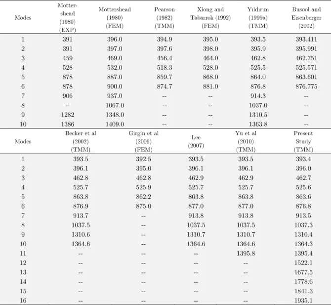
, 0.3, G=79.269 GPa, 0 8.5744, Kn=Kb=1.1, Fixed-Fixed ends. The results are presented in Table (1). From Table (1) it is observed that the natural frequencies obtained by the transfer matrix method show a good harmony. The minor differences between the present study and Reference (Yıldırım, 1999a) probably steam from the number of terms considered in the numerical computation of the overall transfer matrix.
Modes
Motter-shead (1980) (EXP)
Mottershead (1980) (FEM)
Pearson (1982) (TMM)
Xiong and Tabarrok (1992)
(FEM)
Yıldırım (1999a) (TMM)
Busool and Eisenberger
(2002)
1 391 396.0 394.9 395.0 393.5 393.411
2 391 397.0 397.6 398.0 395.9 395.991
3 459 469.0 456.4 464.0 462.8 462.751
4 528 532.0 518.3 528.0 525.5 525.571
5 878 887.0 859.7 868.0 864.0 863.601
6 878 900.0 874.7 881.0 876.8 876.775
7 906 937.0 -- -- 914.3 --
8 -- 1067.0 -- -- 1037.0 --
9 1282 1348.0 -- -- 1310.5 --
10 1386 1409.0 -- -- 1363.8 --
Modes
Becker et al (2002) (TMM)
Girgin et al (2006) (FEM)
Lee (2007)
Yu et al (2010) (TMM)
Present Study (TMM)
1 393.5 392.5 393.5 393.5 393.4
2 396.1 395.0 396.1 396.1 396.0
3 462.8 462.8 462.9 462.9 462.7
4 525.7 525.9 525.7 525.7 525.6
5 863.8 862.2 863.8 863.8 863.6
6 876.9 875.0 877.0 877.0 876.8
7 913.7 -- 913.8 913.8 913.5
8 1037.5 -- 1037.5 1037.5 1037.3
9 1310.6 -- 1310.7 1310.7 1310.4
10 1364.6 -- 1364.6 1364.6 1364.3
11 -- -- -- 1395.8 1395.4
12 -- -- -- -- 1522.1
13 -- -- -- -- 1677.5
14 -- -- -- -- 1778.6
15 -- -- -- -- 1841.3
16 -- -- -- -- 1935.1
The widely held formula for the fundamental frequency in axial mode, faxial (in Hz), in the literature (Haringx, 1949) is given by
2
2 8
1 axial
axial
G nCR
f (40)
In the second example a cylindrical helical spring under an axial static load compressed to half of its free axial length is considered. Material and geometric properties of the spring having clamped supports at two ends are: Lo/D=5, /Lo=0.5, n=30, C=10, d=1mm, 7900kg/m3, 0.3
G=79.269 GPa. Those properties correspond to 0 3.036789 (in degrees),
1.517861 (in de-grees), faxial118.80Hz (axial 746.44rad/s) by considering equations L0/Dntan0 and
tan
/D n
L (where L0L). In this example, since the helix pitch angle is very small (<<5o), the effects of the axial force and bending moment on the tip deflection may be negligible. However, the shearing effect should be considered.
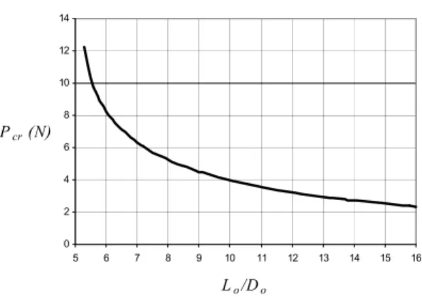
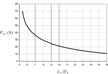
The corresponding axial static load to the prescribed deflection is to be found as Po=8.2532 Newton by using Equation (18). This value was found as 8.242 by Becker et al. (2002). Now, Let’s check whether the applied axial force, P0, is equal to critical buckling load, Pcr, by using Figure (3).
As shown from this figure Pcr 12N for this example. This verifies that the first frequency will be found is certainly to be the fundamental frequency of the spring loaded by a static axial load.
Figure 3: Critical buckling loads obtained in a static manner (Yıldırım, 2009b).
For the sake of the comparison, by using Equations (16) and (18), the first 16 natural dimensionless frequencies of the spring considered are presented in Table (2) in a comparative manner with benchmark results. Since the helix pitch angle is small, the additional terms considered in the present study will be gained an importance. As shown from Table (2) those terms affect just symmetric and asymmetric bending modes. As expected, for small helix angles, the analytical theory may give acceptable results. Again a good accordance between Becker et al’s (2002) and present results is observed. It may be noted that Becker et al. (2002) computed those frequencies by employing Equation (17).
C=10, n=30
0 2 4 6 8 10 12 14
5 6 7 8 9 10 11 12 13 14 15 16
Lo/Do
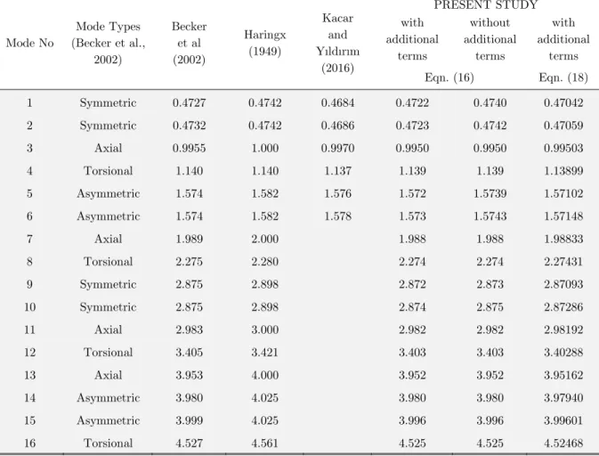
By using Equation (18) which considers the whole effect of the resultant force on the tip deflection of the spring, the present first 16 natural frequencies for a cylindrical helical spring considered are tabulated in Table (3) based on the Timoshenko and Bernoulli-Euler hypotheses. As shown from the table, the differences between two theories become visible for P00.
Mode No
Mode Types (Becker et al.,
2002)
Becker et al (2002)
Haringx (1949)
Kacar and Yıldırım
(2016)
PRESENT STUDY with
additional terms
without additional
terms
with additional
terms
Eqn. (16) Eqn. (18)
1 Symmetric 0.4727 0.4742 0.4684 0.4722 0.4740 0.47042
2 Symmetric 0.4732 0.4742 0.4686 0.4723 0.4742 0.47059
3 Axial 0.9955 1.000 0.9970 0.9950 0.9950 0.99503
4 Torsional 1.140 1.140 1.137 1.139 1.139 1.13899
5 Asymmetric 1.574 1.582 1.576 1.572 1.5739 1.57102
6 Asymmetric 1.574 1.582 1.578 1.573 1.5743 1.57148
7 Axial 1.989 2.000 1.988 1.988 1.98833
8 Torsional 2.275 2.280 2.274 2.274 2.27431
9 Symmetric 2.875 2.898 2.872 2.873 2.87093
10 Symmetric 2.875 2.898 2.874 2.875 2.87286
11 Axial 2.983 3.000 2.982 2.982 2.98192
12 Torsional 3.405 3.421 3.403 3.403 3.40288
13 Axial 3.953 4.000 3.952 3.952 3.95162
14 Asymmetric 3.980 4.025 3.980 3.980 3.97940
15 Asymmetric 3.999 4.025 3.996 3.996 3.99601
16 Torsional 4.527 4.561 4.525 4.525 4.52468
Table 2: The first 16 natural dimensionless frequencies ( f / faxial) for a cylindrical helical spring under a static axial load compressed to half of its free axial length.
Modes Po=0 Po=8.2532 N {with eqn. (18)}
TIMOSHENKO BERNOULLI TIMOSHENKO BERNOULLI
f (Hz)
axial
f
f / f (Hz)
axial
f
f / f (Hz)
axial
f
f / f (Hz)
axial
f f /
1 79.6940 0.67082 79.7693 0.67146 55.8861 0.47042 56.2129 0.47317
2 79.7155 0.67100 79.7907 0.67164 55.9066 0.47059 56.2335 0.47335
3 118.363 0.99632 118.687 0.99905 118.209 0.99503 118.531 0.99773
4 135.010 1.13645 135.180 1.13787 135.313 1.13899 135.486 1.14045
5 191.610 1.61287 191.939 1.61565 186.638 1.57102 187.458 1.57793
6 191.703 1.61366 192.033 1.61643 186.692 1.57148 187.512 1.57838
7 236.538 1.99106 237.186 1.99651 236.215 1.98833 236.858 1.99375
8 269.569 2.26910 269.909 2.27196 270.189 2.27431 270.536 2.27723
9 327.402 2.75591 328.147 2.76217 341.067 2.87093 342.431 2.88241
10 327.713 2.75852 328.455 2.76477 341.296 2.87286 342.686 2.88456
11 354.446 2.98355 355.415 2.99170 354.253 2.98192 355.254 2.99034
12 403.364 3.39532 403.874 3.39961 404.263 3.40288 404.788 3.40730
13 467.859 3.93820 469.101 3.94865 469.453 3.95162 470.759 3.96261
14 473.721 3.98755 474.990 3.99822 472.753 3.97940 475.060 3.99881
15 477.471 4.01911 478.798 4.03028 474.727 3.99601 477.070 4.01573
16 536.179 4.51328 536.859 4.51901 537.533 4.52468 538.239 4.53063
Table 3: The present first 16 natural frequencies for a cylindrical helical spring based on the Timoshenko and Bernoulli-Euler hypotheses by using Equation (18).
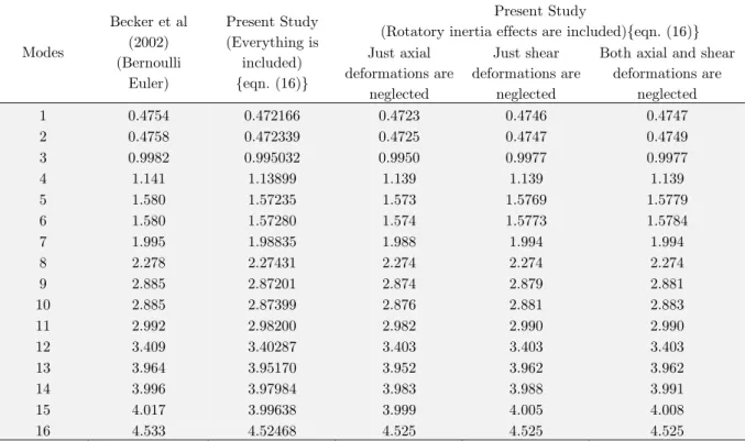
Modes
Becker et al (2002) (Bernoulli
Euler)
Present Study (Everything is
included) {eqn. (16)}
Present Study
(Rotatory inertia effects are included){eqn. (16)} Just axial
deformations are neglected
Just shear deformations are
neglected
Both axial and shear deformations are
neglected
1 0.4754 0.472166 0.4723 0.4746 0.4747
2 0.4758 0.472339 0.4725 0.4747 0.4749
3 0.9982 0.995032 0.9950 0.9977 0.9977
4 1.141 1.13899 1.139 1.139 1.139
5 1.580 1.57235 1.573 1.5769 1.5779
6 1.580 1.57280 1.574 1.5773 1.5784
7 1.995 1.98835 1.988 1.994 1.994
8 2.278 2.27431 2.274 2.274 2.274
9 2.885 2.87201 2.874 2.879 2.881
10 2.885 2.87399 2.876 2.881 2.883
11 2.992 2.98200 2.982 2.990 2.990
12 3.409 3.40287 3.403 3.403 3.403
13 3.964 3.95170 3.952 3.962 3.962
14 3.996 3.97984 3.983 3.988 3.991
15 4.017 3.99638 3.999 4.005 4.008
16 4.533 4.52468 4.525 4.525 4.525
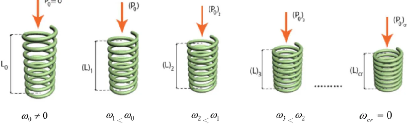
0
0
1<0 2<1 3<2
Figure 4: Relation between frequencies and static axial load for the same spring.
7 NUMERICAL EXAMPLE FOR BUCKLING AND FREE VIBRATION WITH A STATIC AXIAL
FORCE
As it is well known, the critical buckling loads may also be determined in a dynamic manner (Yıldırım, 2012; Kobelev, 2014). In this method, for a given static axial load, from P0 to Pcr at which the fundamental frequency of the spring becomes zero, the fundamental frequencies of the spring are searched.
The effect of especially bending moment on the tip deflection increases with increasing helix pitch angle. Increasing the helix pitch angle results in an increase in Lo/D ratios while the number of active turns remain constant. To see the effect of bending moment on both the critical buckling load and the free vibration frequencies of a compressed spring, here a cylindrical helical spring having the same properties of the spring in the previous example, except n=5 and Lo/D=10, is studied. Those prop-erties are in contact with 0 32.4816366o and faxial712.8014 Hz (axial4478.663 rad/s).
By using Equation (18), it is almost impossible to distinguish directly of the initial force which corresponds to a given /L0 ratio. This may be done by numerically as shown in Table (5).
0
P (N) ( ).100 0
L
t
T
100 ). (
0
L
b
T
100 ). (
0
L
b
M
100 ). (
0
L
t
M
100 ). (
0
L
Total
1 0,002 0,0004 0,133 0,426 0,561
5 0,012 0,0017 0,664 2,129 2,807
10 0,023 0,0033 1,328 4,259 5,613
15 0,035 0,0050 1,992 6,388 8,420
20 0,047 0,0066 2,655 8,518 11,23
23,5 0,055 0,0078 3,120 10,01 13,19
Table 5: Percent effects of the each stress resultants on the relative compression for some applied axial forces.
From the Table (5), for 10cm, it is stated that while the percent contribution of the bending moment on the total tip deflection is about 24%, this value is about 76% for the torsional moment.
0
cr
For this example present free vibration frequencies and critical buckling load which are both obtained by using Equation (18) are presented in Table (6). The critical buckling load corresponds
cr
P =21.283 (N) at which the fundamental frequency is 1 1.31086 (Hz), critical helix pitch angle
is cr=29.287 (o), and the relative compression is /L0= 0.11897.
From the Table (6) it is shown that after determining the critical buckling load, the fundamental frequency is lost and replaced by the lowest second frequency. This means that buckling occurred. For the spring with a static axial force, natural frequencies higher than the first are all shifted forward. The numerical free vibration analysis continues to produce natural frequencies for the post buckling case.
(o) 32.48 31.01 30.25 29.49 29.33 29.30 29.29 29.29 29.29 29.28) (
0 N
P 0 10 15 20 21 21.2 21.28 21.285 21.29 21.3
0
/L
0 0.056 0.084 0.112 0.117 0.119 0.119 0.119 0.119 0.119
Modes
1 222.642 169.226 129.217 59.7461 28.2138 15.3332 3.18760 10.7438 10.0724 8.57331 2 222.894 169.362 129.272 60.5366 30.1637 18.7829 11.3754 458.462 458.428 458.360 3 563.766 523.956 497.573 467.041 460.392 459.039 458.496 465.656 465.622 465.554 4 579.415 532.768 505.281 474.283 467.595 466.236 465.690 574.289 574.285 574.276 5 599.363 585.097 580.029 575.431 574.541 574.364 574.294 718.852 718.860 718.876 6 684.590 700.701 708.774 716.801 718.397 718.716 718.844 949.949 949.934 949.904 7 1005.47 981.556 968.123 953.776 950.802 950.204 949.964 974.033 974.018 973.987 8 1033.48 1006.84 992.637 977.901 974.893 974.290 974.048 1054.26 1054.25 1054.24 9 1083.05 1068.97 1062.30 1055.87 1054.61 1054.36 1054.26 1357.64 1357.63 1357.61 10 1351.43 1377.39 1368.61 1359.87 1358.14 1357.79 1357.65 1368.61 1368.60 1368.58 11 1394.88 1380.08 1378.87 1370.76 1369.09 1368.75 1368.62 1416.67 1416.68 1416.71 12 1405.88 1390.37 1398.13 1412.82 1415.81 1416.41 1416.65 1442.35 1442.35 1442.35 13 1442.43 1442.24 1442.23 1442.31 1442.34 1442.35 1442.35 1936.80 1936.82 1936.84 14 1886.91 1909.39 1921.25 1933.56 1936.08 1936.59 1936.79 2091.97 2091.99 2092.03 15 2004.48 2045.51 2066.10 2086.69 2090.80 2091.62 2091.95 2609.91 2609.94 2609.99
16 2505.54 2552.70 2577.50 2603.17 2608.41 2609.46 2609.89 2743.34 2743.36 2743.40
Table 6: Free vibration frequencies and critical buckling load which are both obtained by using Equation (18).
(o) 32.48 30.25 30.79 30.56 30.33 30.27 30.22 30.17 30.16 30.10 )(
0 N
P 0 10 15 17 19 19.5 20 20.4 20.5 21
0
/L
0 0.043 0.064 0.073 0.081 0.083 0.085 0.087 0.087 0.089
Modes
1 222.642 165.142 121.753 97.7279 64.1083 52.1781 36.3886 14.0473 4.70327 438.639
2 222.894 165.283 121.817 97.9632 64.7290 53.0238 37.7138 17.4083 442.687 445.634
3 563.766 515.256 483.458 469.384 454.468 450.600 446.673 443.489 449.692 568.302
4 579.415 523.687 490.866 476.579 461.529 457.638 453.693 450.497 568.906 712.619
5 599.363 582.060 575.610 573.149 570.718 570.113 569.509 569.026 711.965 919.762
6 684.590 697.987 704.689 707.351 709.996 710.654 711.310 711.835 922.131 945.238
7 1005.47 968.179 947.128 938.261 929.140 926.820 924.483 922.603 947.550 1041.01
8 1033.48 993.714 972.302 963.447 954.425 952.143 949.852 948.011 1041.99 1333.96
9 1083.05 1062.67 1052.76 1048.83 1044.92 1043.94 1042.96 1042.18 1335.47 1340.81
10 1351.43 1366.59 1351.94 1345.99 1340.00 1338.49 1336.98 1335.77 1342.38 1405.03
11 1394.88 1370.82 1359.18 1353.19 1347.05 1345.50 1343.94 1342.69 1403.80 1408.38
12 1405.88 1381.77 1390.55 1395.29 1400.14 1401.36 1402.58 1403.56 1409.26 1888.77
13 1442.43 1426.98 1418.73 1415.34 1411.89 1411.02 1410.14 1409.44 1888.76 2075.31
14 1886.91 1888.13 1888.50 1888.61 1888.70 1888.72 1888.74 1888.75 2073.62 2547.47
15 2004.48 2038.12 2055.01 2061.78 2068.54 2070.24 2071.93 2073.28 2546.44 2729.88
16 2505.54 2525.26 2535.28 2539.32 2543.38 2544.40 2545.42 2546.24 2727.99 3336.15
Table 7: Free vibration frequencies and critical buckling load which are both obtained by using Equation (17).
(o) 32.48 31.15 29.78 29.74 29.70 29.66 29.65 29.64) (
0 N
P 0 10 20 20.3 20.6 20.9 20.95 21
0
/L
0 0.050 0.101 0.102 0.104 0.106 0.106 0.106
Modes
1 222.642 167.554 51.2411 42.3180 30.8474 10.3869 9.00528 451.454
2 222.894 167.693 52.1726 43.5052 32.5441 14.8720 451.820 458.566
3 563.766 520.406 458.675 456.531 454.368 452.185 458.934 572.004
4 579.415 529.054 465.820 463.665 461.492 459.300 572.054 716.061
5 599.363 583.855 573.021 572.715 572.410 572.105 715.987 938.074
6 684.590 699.598 714.580 715.025 715.469 715.913 938.259 62.721
7 1005.47 976.097 941.769 940.665 939.557 938.445 962.906 1049.08
8 1033.48 1001.48 966.394 965.295 964.194 963.090 1049.16 1348.39
9 1083.05 1066.40 1050.62 1050.16 1049.70 1049.23 1348.50 1357.55
10 1351.43 1373.01 1350.64 1349.96 1349.29 1348.61 1357.66 1411.45
11 1394.88 1376.67 1359.82 1359.14 1358.46 1357.77 1411.31 1428.33
12 1405.88 1386.51 1408.67 1409.50 1410.34 1411.17 1428.36 1916.67
13 1442.43 1435.99 1429.04 1428.83 1428.61 1428.40 1916.59 2084.62
14 1886.91 1900.71 1915.18 1915.62 1916.07 1916.52 2084.43 2583.34
15 2004.48 2042.53 2080.79 2081.94 2083.09 2084.24 2583.15 2737.34
16 2505.54 2541.48 2579.43 2580.60 2581.77 2582.95 2737.14 3361.80
As it is well known, the common equation numbered by (16) consider the deflection due to the just torsional moment for small helix angles. Finally, to see the effect of Equation (16), Let’s consider Table (8). In this situation, natural frequencies have the numerical values between Table (6) and Table (7).
Figure (5) shows the critical buckling loads obtained in a static manner for this example. The numerical values of the critical buckling loads calculated by both static and dynamic manners are exhibited in Table (9) in a concise way. From this table, it may be concluded that critical buckling loads obtained by using Equation (18) gives the higher values. This means that critical buckling loads found by Equations (16) and (17) fell in a safe region in design for this example.
Figure 5: Critical buckling loads obtained in a static manner for C=10 and n=5 (Yıldırım, 2009b).
Equation
used Pcr(N) cr(degree)
0
L
cr
(%)
Present Study
19 21.283 29.287 11.9
18 20.4 30.17 8.7
17 20.9 29.66 10.6
Yıldırım (2009b) -- 21.299 29.271 11.96
Table 9: Critical buckling loads and corresponding deformations of the spring.
8 CONCLUSIONS AND DISCUSSIONS
Vibration analysis of the springs under axial static loads requires a precise study to understand the real behavior of the springs. To accomplish such an accurate analysis first the most comprehensive differential equations which comprise some additional terms for taking into account for the axial and shear deformation terms on the buckling and vibration were used, second the exact total tip defor-mation for a spring subjected to an axial force is calculated by using a global analytical formula
C=10, n=5
0 10 20 30 40 50 60 70 80
5 6 7 8 9 10 11 12 13 14 15 16
Lo/Do
considering the whole effect of the resultant forces on the tip deflection, third the overall exact transfer matrix is numerically calculated by using an effective numerical algorithm. As a result, those choices render an accurate numerical free vibration analysis of cylindrical helical springs under a static axial force based on the transfer matrix method.
The vibration modes correspond to low-frequency motions are strongly affected by the presence of applied static axial loads as Kobelev stated (2014). In the present study the forward-shifting phe-nomenon of the natural frequencies in higher modes are observed after buckling. That is with a small increment of the value of the applied static load, one may get the next natural frequency after buckling occurs. Before determining the natural frequencies subjected to a certain static axial force, the axial force considered should be tested for the critical buckling load. The author offers that a free and/or forced vibration analysis with an axial static load should not be performed individually without checking buckling loads.
Acknowledgements
The material covered in this paper is based upon work was supported by the research grant 106M307 from Technical Research Council of Turkey (TUBITAK).
References
Becker L.E. and Cleghorn W.L. (1992). On the buckling of helical compression springs. Int. J Mech. Sci. 34(4):275– 282
Becker L.E., Chassie G.G., Cleghorn W.L. (2002). On the natural frequencies of helical compression springs. Interna-tional Journal of Mechanical Sciences 44(4): 825-841.
Busool W. and Eisenberger M. (2002). Free Vibration of Helicoidal Beams of Arbitrary Shape and Variable Cross Section. J. Vib. Acoust. 124(3), 397-409.
Chassie G.G, Becker L.E, Cleghorn W.L. (1997). On the buckling of helical springs under combined compression and torsion. Int. J Mech. Sci. 39(6):697–704
Farshad M. (1980). Wave propagation in prestressed curved rods. J. Eng. Mech. Div. 106: 395–408.
Frikha A., Treyssède F., Cartraud P. (2011). Effect of axial load on the propagation of elastic waves in helical beams. Wave Motion 48 : 83–92.
Girgin K., Olgun O., Darılmaz K., and Omurtag M.H. (2006). Dynamic analysis of cylindrical and conical helices by mixed FEM, Journal of Turkish Chamber of Civil Engineering (İMO Teknik Dergi) 4003-4023 (in Turkish)
Haktanır V. (1994). Analytical expression of the parameters effecting the spring stiffness of helical springs of arbitrary shaped subjected to compression force. 6. International Symposium, Design and Manufacture of Machines, METU, Ankara, September 21-23, 473-482.
Haktanır V. and Kıral E. (1992). Computation of free vibration frequencies of helical springs subjected to axial load. Journal of Engineering Faculty of Isparta of Akdeniz University 6: 201-218.
Haktanır, V. (1995). The Complementary Functions Method for the Element Stiffness Matrix of Arbitrary Spatial Bars of Helicoidal Axes. Journal International Journal for Numerical Methods in Engineering 38 (6): 1031-1056 Haringx J. A. (1949). On highly compressible helical springs and rubber rods, and their application for vibration-free mountings. Philips Research Reports 4: 49–80.
Kacar İ. and Yıldırım V. (2011). Natural frequencies of composite cylindrical helical springs under compression. Vibra-tion Problems ICOVP 2011. The 10th InternaVibra-tional Conference on VibraVibra-tion Problems, Springer Proceedings in Phys-ics, Editors: Náprstek, J., Horáček, J., Okrouhlík, M., Marvalová, B.,Verhulst, F., Sawicki, J.T. (Eds.) 119-124. Kacar İ. and Yıldırım V. (2016) Free Vibration/Buckling Analyses of Non-Cylindrical Initially Compressed Helical Composite Springs. Mechanics Based Design of Structures and Machines DOI: 10.1080/15397734.2015.1066687 Kobelev V. (2014). Effect of static axial compression on the natural frequencies of helical springs. Multidiscipline Modeling in Materials and Structures 10 (3): 379 – 398. http://dx.doi.org/10.1108/MMMS-12-2013-0078
Lee J. (2007). Free vibration analysis of non-cylindrical helical springs by the pseudospectral method. Journal of Sound and Vibration 305 (3): 543–551.
Mottershead J.E. (1982). The large displacements and dynamic stability of springs using helical finite elements. Int. J Mech. Sci. 24(9):547–558
Mottershead J.E. (1980). Finite elements for dynamical analysis of helical rods, International Journal of Mechanical Sci. 22: 267–283.
Özbek T. (1966). On the general buckling theory of elastic curved rods, Ph.D. Thesis (in Turkish), Istanbul Technical University, Faculty of Civil Eng. Turkey.
Pearson D. (1982). The transfer matrix method for the vibration of compressed helical springs. J Mech. Eng. Sci. 24:163–171.
Pestel E.C. and Leckie F.A. (1963). Matrix Methods in Elastomechanics, NewYork, McGraw-Hill.
Tabarrok B. and Xiong Y. (1992). A spatially curved and twisted rod element for buckling analysis. Int. J Solids Struc. 29 (23):3011–3023.
Ünlüsoy Y.S. (1983). Modelling helical springs for the dynamic behavior. Middle East Technical University (METU) Journal of Applied Researches 3(9): 45-57 (In Turkish).
Wahl A.M. (1963). Mechanical Springs, Second Edition, McGraw-Hill, New York.
Wittrick W.H. (1966). On elastic wave propagation in helical spring. Int. J Mech. Sci. 8(1):25–47
Xiong Y. and Tabarrok B. (1992). A finite element model for the vibration of spatial rods under various applied loads. International Journal of Mechanical Sciences 34 (1): 41-51.
Yalçın V. (1984). Finite element mobility analysis of helical coil springs, MS Thesis, The Graduate School of Natural and Applied Sciences, METU, Turkey.
Yıldırım V. (1996). Investigation of parameters affecting free vibration frequency of helical springs. International Jour-nal for Numerical Methods in Engineering 39: 99–114.
Yıldırım V. (1999). An efficient numerical method for predicting the natural frequencies of cylindrical helical springs. International Journal of Mechanical Sciences 41/ 8: 919-939.
Yıldırım V. (2009a). Numerical buckling analysis of cylindrical helical coil springs in a dynamic manner, Int. J Eng. Appl. Sci. 1 (1), 20-32.
Yıldırım V. (2009b). Report: Buckling and Free Vibration Problems of Helical Compression Springs with Pre-Load: A Software Program and Design Charts. Ankara: Tübitak (The Scientific and Technological Research Council of Turkey). Yıldırım V. (2012). On the linearized disturbance dynamic equations for buckling and free vibration of cylindrical helical coil springs under combined compression and torsion. Meccanica 47: 1015–1033.
Yıldırım V. (2016). Exact determination of the global tip deflection of both close-coiled and open-coiled cylindrical helical compression springs having arbitrary doubly-symmetric cross-sections. Int. J. Mech. Sciences, 115–116: 280-298.