ABSTRACT: The developments of innovative adaptive structures on Unmanned Aerial Vehicles (UAVs), such as morphing wings, can potentially reduce system complexities by eliminating control surfaces and their auxiliary equipment. This technology has the potential of allowing a UAV to adapt to different mission requirements or to execute a particular mission more effectively by maintaining an optimum airfoil section over a range of speeds for different segments of a mission proile. Studies on a number of smart materials candidates are currently available in the open literature to achieve wing morphing. The material selection depends on several factors including fast dynamic response, low weight, capability to operate over a wide range of light conditions and low power consumption. This paper presents a review on smart materials technologies for UAV morphing wings. A numerical study in terms of power requirements is also presented for two morphing wing concepts: lapped and twisted wing planforms. The energy calculations for both morphing conigurations were based on a two-step procedure. The irst step consists of computing the aerodynamic energy using an in-house Vortex-Lattice (VL) based program. Subsequently the pressure ield obtained from the irst step is then mapped into a inite element mesh and the structural strain energy is calculated. The numerical results indicated that lapped morphing wings have a better aerodynamic performance when compared to twisted wings and different morphing levels can be achieved using lighter smart materials with lower speciic energy for this coniguration.
KEYWORDS: Morphing wings, Smart materials, Wing design.
A Numerical Study on Smart Material
Selection for Flapped and Twisted
Morphing Wing Conigurations
Mauricio Vicente Donadon1, Lorenzo Iannucci2INTRODUCTION
he goal of multi-mission capability in military and civil air vehicle systems has created a need for technologies which allow drastic wing shape changes during light. Since most current aircrat are ixed-geometry, they represent a design compromise between conlicting performance requirements in mission segments, such as high-speed cruise, low-speed loiter and low turn radius turn maneuver. If a hybrid aircrat is designed to combine several lights proiles, the wing design must maximize the overall eiciency of the anticipated mission. hrough morphing, the aerodynamics of the aircrat can be adapted in order to optimize performance in each segment by changing shape features such as the camber of the airfoils and the twist distribution along the wing.
Adapting the shape of wings in flight allows an air vehicle to perform multiple, radically different tasks by dynamically varying its light envelope. he wing can be adapted to different mission segments, such as cruise, loitering and high speed maneuvering by sweeping, twisting and changing its span, area and airfoil shape. Within this context, morphing wing technology is considered to be a key component in next-generation unmanned aeronautical vehicles (UAVs) for military and civil application. he design of UAVs demands a multidisciplinary integration of diferent engineering areas, including aerodynamics, structural elasticity, control and actuators/sensors dynamics as schematically shown in Fig. 1. he work presented in this paper is part of an ongoing international research program on UAVs between the Department of Aeronautics, at Imperial College
1.Instituto Tecnológico de Aeronáutica – São José dos Campos/SP – Brazil 2.Imperial College London – London – United Kingdom
Author for correspondence: Maurício Vicente Donadon | Instituto Tecnológico de Aeronáutica | Praça Eduardo Gomes, 50 – Vila das Acácias | CEP: 12228-901 São José dos Campos/SP – Brazil | Email: [email protected]
London-UK, and the Instituto Tecnológico de Aeronáutica-ITA, in Brazil. he paper is focused on a review on smart materials technologies for UAV morphing wings. A numerical study in terms of power requirements is also presented for two morphing wing concepts: lapped and twisted wing planforms. he energy calculation for both morphing conigurations is based on a two-step procedure. he irst step consists of computing the aerodynamic energy using an in-house Vortex-Lattice (VL) based program. Subsequently, the pressure ield obtained from the first step is then mapped into a finite element mesh and the structural strain energy is calculated.
REVIEW ON MORPHING WING
TECHNOLOGY
MORphing Wing COnCEpTS
he diferent concepts based on smart material technology, currently available in the open literature for UAVs light control, can be classiied into four distinct groups according to the adopted solution strategy (Fontanazza et al., 2006):
• Wings with local morphing capabilities; • Wings with global morphing capabilities;
• Composite wings with multi-stable structural behaviour; • Wings with variable stifness structural parts.
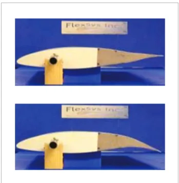
he solutions adopted for wings with local morphing capabilities rely on the deformation of compliant parts of the wing. Examples of wings with local morphing capabilities were presented by Lim et al. (2005), in which the authors proposed a compliant trailing edge configuration with lightweight piezo-composite actuator (LIPCA), bonded on the upper part of the skin. Kota et al. (2003) proved the efectiveness of novel compliant mechanisms to change the wing chamber of an airfoil to minimise drag without causing low separation (Fig. 2)
In this case, power is required in order to deform both the (compliant) structure and to generate the required aerodynamic forces. Because of the high chord-wise bending stifness of a typical closed wing section, twisting the whole wing, or part of the wing, would be more efective (Barrett and Brozoski, 1996). he solution adopted for wings with global morphing capabilities implies in deforming the whole wing, such as twisting the wing along its entire span. his solution
has been considered for light control of ixed wing aircrat, rotorcraft, and missiles. Previous concepts made use of directionally attached piezoelectric actuators (DAP), embedded within the outer skin of high aspect ratio wings (Barrett and Brozoski, 1996). For low aspect ratio wings and missiles ins, designs with integral main spar and active torque plate were considered (Barrett, 1995). Later designs employed a bending element included into the wing, in order to achieve greater delections, actively pitching the aerodynamic surface.
Aerodynamics Structural
elasticity Control
Morphing wing design
Actuator/Sensor dynamics
Figure 1. UAVs design methodology.
More recently, Cesnik and Brown (2003) studied a solution with anisotropic piezocomposites (AFCs) distributed along a high aspect ratio wing. It has been concluded that novel single crystals ibre composites may be capable of providing the required control capability. Composite wings with multi-stable structural behaviour exploit the possibility of changing the shape of an unsymmetric composite laminate from one stable position to another, supplying a small amount of energy (Schultz, 2005) to promote mode switching. he advantage is that no further power is required to keep the structure at an equilibrium coniguration. he main drawback is that few (two or three) stable shapes are possible so that the resulting control system could not be used for manoeuvring over diferent range of speeds.
Wings with variable stifness structural parts exploit the energy on the luid (aerodynamic forces) rather than directly using the smart actuators to change the shape of the wing. Griin and Hopkins (1997) suggested the Variable Stifness Spar (VSS) concept in order to improve the manoeuvrability of flexible aircrafts (e.g. to counteract aileron reversal). he solution is based on the simultaneous actuation of a control surface and modiication of the wing stifness. In the VSS, a spar made of separated parts, linked with hinges, can be rotated in order to change its ability to react the shear forces (Chen et al., 2000). Another design, the Torsion-Free (TF) wing concept, consists of two closely spaced very stif spars which carry most of the shear. The stiffness of the other spars is reduced in order to produce a wing with low torsional stifness. Two VSS, placed along the leading and trailing edge, are used to tune the wing torsional stifness (Chen et al., 2000). he TF concept was also investigated by Changho et al. (2002), employing variable stifness Shape Memory Alloys (SMA) spars to increase roll efectiveness. Amprikidis et al. (2005) have recently developed an “adaptive internal structure” to twist a wing, by moving the position of the elastic axis. his can be obtained by rotating two spars or changing their chord-wise position. With this approach, a considerably lower amount of energy is required to twist the wing and keep it in the desired position. For the speciic problem of UAV roll control, third and forth concepts seem to be the most promising ones. Smart materials can be employed either to twist the whole wing or to tune its stifness. For the latter solution, in order to guarantee fast response and high
eiciency, the use of “active materials” in an “intrinsically adaptive” mode is a requirement.
CAnDiDATE MATERiAlS fOR SMART MORphing WingS
Smart materials are able to respond to a stimulus in a useful and reproducible manner (Suleman, 2001). he materials themselves are not “smart”, in the sense that they passively react to an input rather than making decisions or adapting themselves to the environment. A more accurate deinition proposed by Kornbluh et al. (2004) classifies them into “Intrinsically adaptive materials” and “Active materials”. Intrinsically adaptive materials are materials subjected to transformations in their molecular or microscopic structure due to a particular external stimulus (usually characterized by a small energy content regarding the deformation energy within the material), resulting in changes in mechanical properties. he SMA and shape memory polymers (SMP) are examples of intrinsically adaptive materials.Active materials act as transducers, converting some forms of energy (typically electrical, magnetic, and thermal) into mechanical energy. Electroactive polymers, piezoelectric ceramics, and magnetostrictive (Terfenol-D) are some examples of active materials. Active materials with high electromechanical coupling can also be used in an “intrinsically adaptive mode”; in this case, they require less power supply, but their performance are more limited.
he main advantages in using smart materials rather than conventional pneumatic or hydraulic actuators are the reduced complexity and improved reliability of the system. Similarly, the potential weight saving and the possibility of using active materials as both actuators and sensors within the structure are clear advantages. he ‘best’ materials and concepts to adopt depend on the speciic morphing purpose. Since the aim is to change the shape of the wing for light control, the morphing system should exhibit:
• Relatively fast dynamics;
• Capability to operate over a wide range of light conditions; • High reliability;
• Capability of repetitive actuations;
• Robustness against uncertainties and disturbances (e.g. gusts);
• Low power consumption;
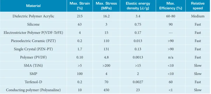
Hence, the ideal material should respond quickly to the external stimuli, be capable of large and recoverable free strains, transform efectively the input energy into mechanical energy, and not to be afected by fatigue issues. Table 1 reports the main characteristics of the most common smart materials (maximum free strain, maximum stress, deformation energy density, eiciency, and relative speed of response). SMAs and SMPs can undergo large free strains and exhibit large blocking forces, but they have slow response and limited efficiency. Piezoelectric Ceramic (PZT) and single crystal piezoceramics, exhibit a much lower free strain, but they are electrically activated, capable of producing quite high blocking forces, and sensibly more eicient ones too. Electroactive polymers exhibit good properties, although they can produce low blocking stress.
ACTUATION ENERGY
REQUIREMENTS ANALYSIS FOR
MORPHING AIRFOILS
One of the most import issues and concerns in smart wing technology have been the actuation energy and power which have to be provided by the vehicle onboard power system. Naturally, a smart wing may almost always require the deformation of some, preferably secondary, wing structure with the actual power requirements heavily dependent on the wing structural
realization and actuation scheme. For the present study, actuation energy of the deformable parts of the wing have been calculated on the basis of the work performed by the aerodynamic forces during the wing morphing in the aerodynamic low ield. he computation of the aerodynamic work has been carried out using an in-house computational program based on the VL method (Donadon and Iannucci, 2006a). he program enables the prediction of lit, pressure distribution, rolling and pitching moment calculations for lapped and twisted wing planforms.
AERODYnAMiC EnERgY COMpuTATiOn
he term aerodynamic energy deined here refers to the total energy induce by the pitching moment acting on the deformable parts of the wing. hus, the expressions for the aerodynamic energy for flapped and twisted wings can be respectively written as follows
N
n=1 Wh = θf Myh(θ)dθ= h
0
∑
Γn∆ynxndθ∫
θf0
∫
(1)N
n=1
Wt = ØfMyt(Ø)dØ= t
0
∑
Γn∆ynxndØ∫
Øf0
∫
(2)where Myh(θ) is the pitching moment around the lapping line,
Myt(θ) is the pitching moment around the twisting line, θ is
the lap tip delection and ø is the wing tip twisting angle. Δyn is the elemental spanwise length, Mnh is the distance between the elemental leading vortex segment and the lapping line
Table 1. Most common smart materials (Fontanazza et al., 2006).
Material Max. Strain
(%)
Max. Stress (Mpa)
Elastic energy density (J/g)
Max. Eficiency (%)
Relative speed
Dielectric Polymer Acrylic 215 16.2 3.4 60-80 Medium
Silicone 63 3 0.75 90 Fast
Electrostrictor Polymer P(VDF-TrFE) 4 15 0.17 --- Fast
Piezoelectric Ceramic (PZT) 0.2 110 0.013 >90 Fast
Single Crystal (PZN-PT) 1.7 131 0.13 >90 Fast
Polymer (PVDF) 0.10 4.8 0.0013 n/a Fast
SMA (TiNi) >5 >200 >15 <10 Slow
SMP 100 4 2 <10 Slow
Terfenol-D 0.2 70 0.0027 60 Fast
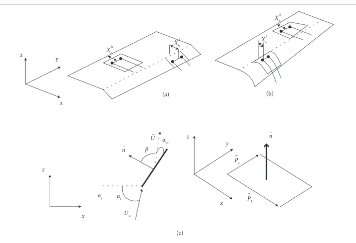
a n d Xnti s t h e d i s t a n c e b e t w e e n t h e e l e m e n t a l l e a d i n g v o r t e x s e g m e n t a n d t h e t w i s t i n g l i n e , a s s h o w n i n F i g . 3 ( b ) . N i s t h e t o t a l n u m b e r o f p a n e l s a n d Γ n i s t h e e l e m e n t a l v o r t e x s t r e n g t h o b t a i n e d b y s o l v i n g t h e f o l l o w i n g l i n e a r s y s t e m o f e q u a t i o n s ,
{Γn} = C_m , nw - Cm , n tan(Ψn) 4π U∞{αm}
-1
w _
( 3 )
w h e r e } = C_m,nw-C a n d m,n-Cm,n
w _
a r e t h e d o w n w a s h a n d s i d e w a s h i n l u e n c e c o e i c i e n t s , r e s p e c t i v e l y , c o m p u t e d a c c o r d i n g t o t h e B i o t - S a v a r t L a w ( B e r t i n , 1989). Ψn is the elemental wing dihedral angle, U∞
is the air low velocity and αm is the elemental angle of attack schematically illustrated in Fig. 3 (c).
inCREMEnTAl pRESSuRE COEffiCiEnT CAlCulATiOn
he incremental pressure coeicient for the n-th panel of the wing is given by (Lamar and Margason, 1971)
∆ cp,n = cnU∞
2Γn
(4)
where cn is the elemental chord. he resultant pressure acting on each panel of the wing can be written in terms of the incremental pressure coeicients as follows
∆Pn = ρU∞∆cp,n 2
2
(5)
Wing STRuCTuRE STRAin EnERgY he wing structure strain energy is given by
{ε}T{σ}
∫∫∫
U= dV
2 1
(6)
where V is the volume occoupied by the structural elements of the wing, {σ} and {ε} are the stress and strain vectors, respectively. By using the inite element method, Eq. (6) can be rewritten in terms of the wing stifness matrix and nodal displacement vector as follows
z
y
(a) (b)
(c) Xnh
Xnh
Xnt
αi αi
αm
U∞
P1
β
z
z
y
x
x
n–
n–
U–
–
P–2
Xnh
x
{δ}T[K]
U=
2
1 {δ}
(7 )
where U is the total strain energy generated during the wing morphing process in the presence of the aerodynamic pressure ield, together with the actuation forces provided by the smart materials to deform the wing.
NUMERICAL SIMULATIONS
This subsection presents a numerical study in terms of actuation energy requirements for both lapped and twisted morphing wing conigurations. he chosen wing dimensions as well as light conditions are typical of small UAVs and they are listed in Tables 2 and 3, respectively. A NACA 0012 airfoil section with dimensions shown in Fig. 4 was assumed for both wings. Both wings have lexible trailing edges made of elastomeric skins, starting at 70% of the chord (region indicated by red dashed line in Fig. 4) and extending up to the full-length chord dimension of the wings. he mechanical properties of the elastomeric skins are depicted in Table 4. In order to compute the pressure ield as well as the aerodynamic work induced by the airflow, an in-house VL program (Donadon and Iannucci, 2006a) based on the formulation described in the previous sections was used. Full wing models were required for both wing conigurations in order to obtain the resultant pressure ield. Once the pressure ield was determined, the aeroelastic problem was then solved by mapping the diferential pressure ield into a inite element model of the deformable parts of the wing and the required elastic energy density determined. he inite element models were developed using the rectangular four-node bi-linear Mindlin shell elements (S4R), with reduced integration available in ABAQUS/ Standard finite element code. The structural analyses were
carried out assuming that the trailing edge was clamped to the remaining part of the wing. he meshes used for the structural and aerodynamic simulations were the same in order to allow a direct pressure mapping between lattices and inite elements. For the lapped wing, the hinging line was positioned at 70% of the chord and the inal lap delection was assumed to be 10°. A convergence study for the pressure ield values indicated that a mesh density of 20 elements, spanwise by 10 elements chordwise, gives results within an accuracy of less
-20 -10 0 10 20
0 50 100 150 200 250
Chord (mm)
h
ic
k
n
es
s
(
m
m
)
Figure 4. NACA 0012 airfoil section.
Table 4. Mechanical properties for the elastomeric skin (Donadon and Iannucci, 2006b).
E [Mpa] 6.90
V 0.30
ρ [kg/m3] 1080
Table 2. Wing dimensions.
Spanwise length [m] 1.40
Root chord [m] 0.27
Tip chord [m] 0.27
Angle of Attack [Degrees] 3.0
Flap delection (for the lapped wing) [Degrees] 10.0
Twisting angle at the wing tip (for the twisted
wing) [Degrees] 10.0
Table 3. Flight conditions and air properties.
U∞ [m/s] 40.0
Altitude [m] 1000
than 1% when compared to iner meshes and, for this reason, this mesh density was used throughout this work. A typical VL mesh for the lapped wing is shown in Fig. 5.
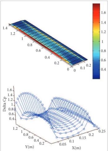
Figure 6 shows the numerical results in terms of pressure distribution for the lapped wing. It can be seen that there is a singularity in the pressure distribution around the hinging line, as expected. his singularity is due to the change in the local angle of attack, which increases the vorticity strength in that region, afecting both lit and pressure distributions.
he dimensions and light conditions for the twisted wing were assumed to be the same as those deined for the lapped wing in order to provide a direct comparison between both wings planforms in terms of lit, pressure distribution, aerodynamic energy and required elastic energy density. he twisting line was placed at 70% of the chord extending throughout the wing span length. he VL mesh and the pressure distribution for the twisted wing are shown in Figs. 7 and 8, respectively.
It can be seen from Fig. 8 that there is an increase in both lit and pressure distributions towards the tip of the wing due to the change of the local angle of attack in that region. It also can be noticed that the lit generated by the twisted wing is lower than the lit generated by the lapped wing. he pitching moment about the twisting line is also lower than the one obtained for the lapped wing. he higher values of pitching moment for the lapped wing were expected, because in the twisted wing, just part of the trailing edge is delected whilst in the lapped wing the whole trailing edge is delected. Figure 9 shows a comparison in terms of lit generation between the lapped and twisted wings for lap delection and the local wing twisting angles ranging from 0° up
Z(m)
Y(m)
X(m)
1.2
1
0 . 8
0 . 6
0. 4
0.2
0 0 0.1 0.2
Figure 5. Vortex lattice mesh for the lapped wing.
1 .4
1 .4
1.2 1.6
1
0 .8
0 .6
0 .4 1.2
1
0 .8 0 .6
0.4 0.2
0.2 0.1 0 0
1.6 1.4 1.2
1.2 1
1 0.8
0.8 0.6
0.6 0.4
0.4
0.2 0.05 X(m) Y(m)
Delta Cp
0.1 0.15
0.2 0.25
Figure 6. Pressure distribution for the lapped wing. to 10°. A comparison in terms of aerodynamic energy generated by lapped and twisted wing planforms is presented in Fig. 10.
Figure 11 compares the aeroelastic strain ield induced in the trailing edge portions of the lapped and twisted morphing wings.
Z(m)
Y(m)
X(m)
1.2 1.4
1
0.8
0.6
0.4 0.2
0 0 0.1 0.2
1.4 1.4 1.2 1.6 1 0.8 0.6 0.4 1.2 1 0.8 0.6 0.4 0.2 0.2 0.1 0 0 1.6 1.4 1.2 1.2 1 1 0.8 0.8 0.6 0.6 0.4 0.4 0.2 0.05 X(m) Y(m) Delta Cp 0.1 0.15 0.2 0.25
Figure 8. Pressure distribution for the twisted wing.
0 1 2 3 4 5 6 7 8 9 10
0.4 0.45 0.5 0.55 0.6 0.65 0.7 0.75 0.8 0.85 0.9
Twisting angle (degrees) CL
Twisted wing
0 1 2 3 4 5 6 7 8 9 10 0.4 0.5 0.6 0.7 0.8 0.9 1 1.1 1.2 1.3 1.4
Flap angle (degrees ) (b ) CL 0 1 2 3 P itc h in g m o m en t ( N.m ) (b)
0 2 4 6 8 10
0 5 10 15 20 A er o d yn am ic e n er gy ( J)
Flap angle (degrees) 0 0.5 1 1.5 P itc h in g m o m en t ( N.m ) (a)
0 1 2 3 4 5 6 7 8 9 10
0 2 4 6 8 10 A er o d yn am ic e n er gy ( J)
Twisting angle (degrees)
Figure 9. Lift generation comparison between twisted (a) and lapped (b) wings.
LE, Max. Principal SNEG, (fraction = -1.0) (Ave. Crit.: 75%)
(a)
+1.408e-02 +1.290e-02 +1.140e-02 +1.173e-02 +1.056e-02 +9.385e-02 +8.212e-02 +7.039e-02 +5.865e-02 +4.692e-02 +3.519e-02 +2.346e-02 +1.173e-02 +0.000e-02
LE, Max. Principal SNEG, (fraction = -1.0) (Ave. Crit.: 75%)
(b) +1.009e-02
+9.245e-02 +8.405e-02 +7.564e-02 +6.724e-02 +5.883e-02 +5.043e-02 +4.202e-02 +3.362e-02 +2.521e-02 +1.681e-02 +8.405e-02 +0.000e-02
Figure 11. Aeroelastic strain ield induced in the trailing edge portions lapped (a) and twisted morphing wings (b).
T able 5 compares the required elastic energy density for both morphing wing conigurations. It can be seen that twisted coniguration requires less actuation energy than lapped wing coniguration. On the other hand, the aerodynamic performance in terms of lit generation is much better for the lapped morphing coniguration. Comparing the required elastic energy density for both wing conigurations with the values provided in Table 1, one can see that only materials 2, 3, 4, 5, 7, 8, and 10 are able to provide the amount of elastic energy density required to deform the wings and sustain them against the aerodynamic pressure ield. However, only Single Crystal (PZN-PT) can provide a fast response with maximum eiciency for both morphing conigurations.
CONCLUSIONS
A review on smart materials technologies and concepts for morphing wing structures was presented and discussed in this paper. A formulation based on the Vortex Lattice Method (VLM) was proposed in order to compute the pressure distribution, lit generation and aerodynamic energy for both lapped and twisted morphing wing planforms. he proposed formulation has been implemented into MATLAB sotware. Numerical simulations were carried out for a typical small UAV, considering two morphing concepts: lapped and twisted wing conigurations. he numerical results indicated that the lapped wing generated higher lit when compared to the twisted wing for the same delection range. However, less aerodynamic power was required to sustain the twisted wing against the aerodynamic loads. hese indings indicated that lapped wing conigurations have a better aerodynamic performance when compared to the twisted wing, however, there is still a need of further investigation considering global twisting instead of twisting just part of the wing. A better aerodynamic performance means that the deformable parts of the wing can be made of lighter smart materials with lower speciic energy, which allows the fabrication of lighter aircrats with higher performance and less fuel consumption. he preliminary study presented in this paper suggests Single Crystal (PZN-PT) materials as potential candidates for smart morphing wing structures due to its fast response with maximum eiciency for both morphing conigurations studied in this work.
ACKNOWLEDGEMENTS
he authors acknowledge the inancial support received for this work from BAe Systems-UK through FLAVIIR SEEDCORN PROJECT.
Table 5. Energy quantities computed for lapped and twisted morphing wing coniguration.
flapped Twisted
Strain energy (J) 0.0760 0.0250
Aerodynamic energy (J) 15.00 9.00
Elastic energy density (J/g) 0.0060 0.0036
Max. Stress (MPa) 0.100 0.072
REFERENCES
Amprikidis, M., Cooper, J.E., Rogerson, C. and Vio, G., 2005, “On The Use of Adaptive Internal Structures for Wing Shape Control”, 46th AIAA/ASME/ASCE/AHS/ASC Structures, Structural Dynamics and Materials Conference, Austin, TX.
Barrett, R. and Brozoski, F., 1996, “Adaptive Flight Control Surfaces, Wings, Rotors and Active Aerodynamics”, Proceedings of the SPIE – International Society for Optics and Photonics, San Diego, CA, v 2717.
Barrett, R., 1995, “All-Moving Active Aerodynamic Surface Research”, Smart Materials and Structures, Vol. 4, No. 2, pp. 41-44. doi: 10.1088/0964-1726/4/2/001.
Bertin, J. J., 1989, “Aerodynamics for Engineers”, 2nd Edition, Prentice-Hall Inc.
Cesnik, C. E. S. and Brown, E. L., 2003, “Active warping control of a joined-wing airplane coniguration”, 44th AIAA/ASME/ASCE/AHS/ASC Structures, Structural Dynamics and Materials Conference, Norfolk, VA.
Chen, P. C., Sarhaddi, D., Jha, R., Liu, D. D., Grifin, K. and Yurkovich, R., 2000, “Variable Stiffness Spar Approach for Aircraft Maneuver Enhancement Using ASTROS”, Journal of Aircraft, Vol. 37, No. 5, pp. 865-871. doi: 10.2514/2.2682.
Changho, N., Chattopadhyay, A. and Youdan K., 2002, “Application of Shape Memory Alloy (SMA) Spars for Aircraft Maneuver Enhancement”, Proceedings of the SPIE - International Society for Optics and Photonics, San Diego, CA, v 4701.
Donadon M. V. and Iannucci L., 2006a, “A Vortex Lattice Program to Compute Aerodynamic Loads in Flapped and Twisted Wing Planforms”, Internal Report-Flaviir SeedCorn Project, Department of Aeronautics, Imperial College London, London, UK .
Donadon M. V. and Iannucci L., 2006b, “Morphing Wing Concepts and Smart Coupons Manufacturing”, Internal Report- Flaviir SeedCorn Project, Department. of Aeronautics, Imperial College London, London, UK.
Fontanazza, A., Talling, R., Jackson, M., Dashwood, R., Dye, D. and Iannucci, L., 2006, “Morphing Wing Technologies Research”, Proceedings of the 1st SEAS DTC Technical Conference, Edinburg, Scotland (CD ROM).
Grifin, K. E. and Hopkins, M. A., 1997, “Smart Stiffness for Improved Roll Control”, Journal of Aircraft, Vol. 34, No. 3, pp. 445-447. doi: 10.2514/2.2191.
Kota, S., Hetrick, J., Osborn, R., Paul, D., Pendleton, E., Flick, P. and Tilmann, C., 2003, “Design and Application of Compliant Mechanisms for Morphing Aircraft Structures”, Proceedings of the SPIE - International Society for Optics and Photonics, San Diego, CA, v 5054.
Kornbluh, R. D., Prahlad, H., Pelrine, R., Stanford, S., Rosenthal, M. A. and von Guggenberg, P. A., 2004, “Rubber to Rigid, Clamped to Undamped: Toward Composite Materials with Wide-Range Controllable Stiffness and Damping”, Proceedings of the SPIE - International Society for Optics and Photonics, San Diego, CA, v 5388.
Lim, S. M., Lee, S., Park, H. C., Yoon, K. J. and Goo, N. S., 2005, “Design and Demonstration of a Biomimetic Wing Section Using a Lightweight Piezo-composite Actuator (LIPCA)”, Smart Materials and Structures, Vol. 14, No. 4, pp. 496-503. doi: 10.1088/0964-1726/14/4/006.
Lamar, J. E. and Margason, J. R., 1971, “Vortex-lattice fortran program for estimating subsonic aerodynamic characteristics of complex planforms”, NASA TN D-6142.
Schultz, M. R., 2005, “A New Concept for Active Bistable Twisting Structures”, Proceedings of the SPIE - International Society for Optics and Photonics, San Diego, CA, v 5764.