ABSTRACT: The location of thin shell parts is always a knotty problem during machining, welding, forming, assembling and inspection operations. This paper mainly focuses on the special location issues in the digital and lexible trimming process for aircraft skins fastened by reconigurable ixture. Firstly, in view of the dynamic change of effective locators, the “X-2-1” location principle was proposed with reference to the “3-2-1” and “N-2-1” location schemes. Secondly, the standard procedure for solving location parameters was summarized in consideration of location admissibility, holding posture, locator layout and so on. Thirdly, a locating experiment was conducted to investigate the positional accuracy of the reconigurable ixture and the calculation accuracy of location parameters solution. Fourthly, a quantitative evaluation method to evaluate the dynamic stiffness of the ixturing system was put forward. Moreover, the effects of location layout on the dynamic stiffness were analyzed using the inite element simulation system for the trimming process. A noticeable appearance had been observed that the cliff effect of the dynamic stiffness of the lexible ixturing system may be induced due to the dynamic change of effective locators. Finally, some conclusions and discussion on future works were given.
KEYWORDS: Thin shell part, Reconigurable ixture, Location principle, Dynamic stiffness, Trimming.
Location Issues of Thin Shell Parts in the
Reconigurable Fixture for Trimming Operation
Hu Fuwen1
INTRODUCTION
he location of a component is one of the most important aspects to achieve the required accuracy during a machining process. Generally, the proper design of clamping and locating arrangements is a diicult task, considering its workpiece geometry, tool paths, set-up time, production scale, resistance to cutting forces, costs, adaptability and so forth. For a long time, towards ixture design becoming a science rather than an art, and towards achieving automation and intelligence of ixture design activities, many theories, tools and approaches have been introduced by many researchers (Wang et al., 2010; Cecil, 2001; Boyle et al., 2011).
However, most part of this research has concentrated on the ixture design for workpieces which can be regarded as rigid bodies. Actually there are also some low rigidity or flexible components in industrial fields, e.g. aircraft skin panels, automotive cover panels, rocket shells and other thin-wall structures. They cannot be seen as rigid bodies due to their inherent lexibility and inevitable deformation caused by external forces or their own weights. hereby, their location issues have always been a particularly knotty problem. To overcome it, the single purpose and dedicated ixtures are oten employed in practical production. Although this approach would be economical for large scale mass manufacturing (e.g. automobile manufacturing), it would lead to long lead time, a large quantity of tooling, and high production costs under small batch manufacturing environments such as the fabrication of aircrats and rockets. herefore, the lexible tooling solutions like reconfigurable fixtures or modular fixtures have been increasingly adopted. hese lexible tooling can be changed, reconigured or reused to suit dimension and shape changes of
1.North China University of Technology – Beijing – China.
compliant parts. In the past decade or so, a great deal of attention has been increasingly directed toward the design, analysis and synthesis of lexible ixturing systems. here are a number of strategies in order to achieve lexibility (Shirinzadeh, 2002), but this paper mainly focused on the reconigurable ixtures designed for machining operations of thin shell parts.
According to available documents, the earliest idea of a reconigurable ixture for thin shell parts trimming process may date back to 1987 (Douglas and Ozer, 1987). About ten years later, the reconigurable ixture for sheet metal machining was reduced to practice (Proctor, 1998). Aterwards, several commercially available reconigurable tooling systems were designed and built, for example, the Pogo
®
lexible tooling system by CNA manufacturing systems (U.S.A.), and the TORRESTOOL®
universal holding ixture by the M. Torres group (Spain). Application results from Northrop Grumman indicated that the Pogo®
lexible tooling system can cut down setup time by about two-thirds on trimming and hole drilling operations on more than 100 different fuselage skin parts (Koelsch, 1998). But these commercially available reconigurable tooling systems for holding compliant parts are extremely expensive (Walczyk and Longtin, 1999). Therefore, many researchers and manufacturers are inclined to develop the reconigurable ixturing devices independently. A reconigurable ixturing system was speciically designed for the drilling of sheet metal parts, which included a T-slot base plate, vertical supports and locating pins (Youcef-Toumi et al., 1987). A novel reconigurable modular system was presented for the ixturing of thin-walled lexible objects, which consists of a base plate, and height-adjustable locators and clamps (Sela et al., 1997). A computer-controlled reconfigurable fixturing device for compliant parts, based on a matrix of individually-stoppable pins lowered by a single rigid platen, has been developed (Walczyk and Longtin, 2000). Zhou et al. (2008) designed a lexible tooling system for large-scale aircrat skins by means of the manipulator’s drivability. For aircrat skins trimming based on the combination of the reconigurable ixture and 5-axis gantry type milling machine tool, the author and co-workers have been studying the process planning method, the trimming process simulation, as well as the equipment development (Hu and Li, 2011; Hu et al., 2012a; Hu et al., 2012b). Besides, to evaluate the milling forces in the trimming process of aircrat skins, the author presented an integrated approach based on the combination of the mechanistic model of milling forces, 3D inite elements simulation of milling operations, and thesupport vector regression methodology (Hu and Li, 2012). Along with the promotion of research, a better systematic understanding of the issue of thin shell components locating in the lexible ixture has been recognized. hese would be described as follows.
In the next section, the author would introduce the lexible manufacturing technology for aircraft skins based on the reconigurable discrete dies and the reconigurable ixture. And the third section mainly focuses on the distinctive location principle that appears in the trimming process of aircraft skins supported by the reconigurable ixture. hen the fourth section illustrates the location parameters solution method, considering location allowance, holding posture, locator layout, etc. hen a location experiment was presented to investigate the location accuracy.Subsequently a quantitative evaluation method for the dynamic stifness of the ixturing system was put forward. Finally, some conclusions and discussion on future works are given.
FLEXIBLE MANUFACTURING MODEL
OF AIRCRAFT SKINS
Aircrat skin panels with the aerodynamic proile are the key components to fabricate fuselage, wings, empennage, and so forth. Generally, skin panels are made of aluminum alloys, however, in the design of new aircrafts, composite panels increasingly tend to be adopted. he accuracy of their shape and dimension and the integrity of their surfaces and edges are extremely stringent. For instance, laser cutting of high-strength aluminum alloys for aerospace applications has been limited, due to its inevitable heat-afected zone (Riveiro
et al., 2008). herefore, the periphery cutting of aircrat skins mainly employs the machining method or the water jet cutting method. In addition to that, skin panels always have low structural rigidity, and complex internal structure and outer shape. hese factors make their forming and machining process very diicult. hereby, the fabrication technology of aircrat skin panels is always a key technology of aircrat manufacturing.
TRADITIONAL FABRICATION PROCEDURE OF AIRCRAFT SKINS
a set of dies, templates and other tooling. he setup time of tooling fabrication accounts for approximately 60 to 80 per cent of the cycle time of one part. Furthermore, due to the analog data transfer through the whole process, the accumulative error is oten relatively large. Additionally, the whole process has to be executed sequentially rather than concurrently. Once a fault (e.g. springback) occurs on any tooling, repair and rework would be necessary.
FLEXIBLE MANUFACTURING MODEL OF AIRCRAFT SKINS
In order to improve the fabrication process of metal skins, a lexible, digital and tooling-less manufacturing model was presented, namely, to replace the dedicated dies by discrete multi-point dies and to replace the dedicated trimming template by the reconigurable ixture (Papazian et al., 2002; Li et al., 2009). As illustrated in Fig. 2, the entire process was accomplished jointly with the digital design, digital tooling, numerical control equipments (e.g. stretch forming machine and CNC machine tool) and digital measure technology. Obviously, the good lexibility of this new manufacturing model can adapt to the dimension and shape changes of aircrat skins, and radically change the traditional fabrication model. As proved in an application experiment performed by Papazian et al. (2002), in this new “tool-less” sheet metal fabrication environment, tooling fabrication time would be reduced by a factor of 8 and labor hours would be reduced to 1/3 of the traditional values.
In the aspect of the lexible stretch forming process, based on the discrete-die concept, undoubtedly, it was David Hardt at MIT and his research group that had done the pioneering work, including the prototype reconigurable multi-points tooling development and the closed-loop shape control technology (Hardt et al., 1981; Walczyk and Hardt, 1998; Munro and
Walczyk, 2007). On the basis of the original MIT work, since 1996 to 2002, a reconigurable tooling for lexible fabrication project was sponsored by the Defense Advanced Research Projects Agency. And the project participators included MIT, Northrop Grumman Corporation, Cyril Bath Company, etc. As a result of this project, a commercially available reconigurable multi-point tooling was designed and built by the Cyril Bath Company in 2002. It was the irst production reconigurable tooling, which had a working volume of 1.06 × 1.83 × 0.30 m3 and consists of 2,688 movable pins (Munro and Walczyk, 2007). In China , approximately since 2003, the scholarly research upon the reconigurable tooling for the stretch forming of aluminum sheet began, and it has been performed chiely by the Li Mingzhe’s research group of Jilin University (Cui et al., 2008; Zhou et al., 2005; Cai et al., 2009)and Li Dongsheng’s research team of Beihang University (Chen, 2006; Huang et al., 2008; Yu
et al., 2011). At 2007, a larger-size (1.216 × 1.824 × 0.305 m3) production reconigurable tooling was designed and built by the Beijing Aeronautical Manufacturing Technology Research Institute (Zhou, 2007). In short, a persistent and concerted efort by many industry and academic researchers has brought the concept of reconfigurable “discrete-die” tooling to the production environment.
he natures of both the reconigurable multi-point tooling and the reconigurable ixture are to use discrete points to approximate a surface. However, as another aspect of the lexible manufacturing model of aircrat skins, the lexible trimming process, based on the reconigurable ixture, seems to have a reverse development history, namely, from reduction-to-practice to academic research. Perhaps there is no such diicult problem as the shape control that remedies the forming defects (e.g. dimpling) which occur in the lexible stretch forming process. Nevertheless, as the chief issue in the development and application of the expensive lexible ixture, the location issue has not been quite clear in academic research. he following factors suggest the particularity and complexity of the workpiece location issues in the lexible trimming process.
• he end efectors are both locators and positioners. Namely, they not only clamp the thin shell part through the vacuum absorption, but also locate the part consistently to prevent the possible deformation. Moreover, the locating and clamping are synchronous.
• When the “lexibility” of multi-point supporting would encounter the “elasticity” of the low-rigidity thin shell part, the location stability would be diicult to assure. Additionally, Section templates
of contour
Forming Wood die
Template for trimming and drilling
Skin part Upper
die
Lower die
with the gradual separation of the thin shell part, and with the loading of the periodical milling forces, the process stability would also be diicult to assure. he whole process stability turns out to be a particularly knotty problem.
• he main task of location layout is to determine the positions and numbers of vacuum end efectors. Two types of restriction should be taken into account: one is geometric constraint, which ensures there is no interference between any two adjacent actuator rods, between any two adjacent lateral frames, and between the machining cutter and the vacuum end efectors; another one is physical constraint, which mainly considers the clamping and processing
stability. he method for planning feasible location layout should be studied.
LOCATION PRINCIPLES
ADEQUATE LOCATION
As it is known, a rigid body has six movement degrees of freedom (3 linear and 3 rotary ones) in a three-dimensional space. If a workpiece can be regarded as a rigid body, it is necessary to arrest the DOF (degrees of freedom) (≤ 6), which Stretch forming over the
reconfigurable tooling
Design, simulation and analysis
Shape measurement
Routing and drilling over the reconfigurable fixture Shape measurement
1 2
11
10
9
7 5
6
8 4
3
Main contents of step [1] include pin height calculation, stretching trajectory calculation and springback compensation; In step[2] the sheet metal would be formed over the reconigurable multi-point tooling; Then, the geometrical precision would be measured via laser scanning; In step[4] the error distribution can be obtained after data processing; If the formation precision cannot meet the requirements, step [1]-[4] begin the cycle again; Otherwise, the surface part would be located in the reconigurable ixture for machining operations; Certainly, before loading the surface part, the location parameter of the reconigurable ixture would be solved; In step [8] the surface part would be machined over the reconigurable multi-point tooling; Then, the machining precision would be measured via laser scanning; In step [10] the error distribution can be obtained after data processing; If the machining precision cannot meet the requirements, step [7]-[10] begin the cycle again.
Z
Y
X
Zi
Xi Yi
0
Figure 3. Discrete points model of a thin shell part.
Figure 4. Manual trimming of aircraft skins on the
dedicated tooling.
affects the machining accuracy. However, due to low rigidity and easy deformation, the thin shell part cannot be considered as a rigid body. As illustrated in Fig. 3, if the elastic surface part is supposed to consiste of n mass points, it would be essential to limit all DOF of n mass points to avoid machining errors. Theoretically, a mass point has three DOF (3 linear), and n tend to be the infinity of integers. Therefore, the only way to limit all 3n DOF entirely is “surface location” provided by the dedicated hard surface fixture (Fig. 4). Moreover, for the cutter penetration, trimming paths should be slotted on the surface of the rigid fixture. Also the trimming or drilling operations can be done by manual cutters, if the plate thickness is less than 2mm, otherwise by the numerical control machine tool.
Apparently, when using the reconigurable ixture to locate the thin shell part (Fig. 2), only the DOF of the mass points close to the vacuum end efectors can be partly restricted. Due to the loaded milling forces and inherent low rigidity, especially in the normal direction, vibration would be unavoidable. In this case, if the required machining accuracy would not be afected, the location status also can be called adequate location. Evidently, adequate location is one of the essential requirements for guaranteeing the machining accuracy.
LOCATION SCHEMES
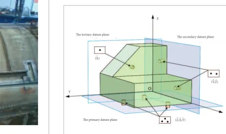
Generally, for a rigid part, the basic location concept is to arrest the motion that may afect the machining accuracy. Speciically, for a prismatic part without an existing hole, the “3-2-1” location principle can arise proper arresting of all the motions. As illustrated in Fig. 5, “3” refers to 3 locators (passive ixture elements) on the primary datum surface; and “2” refers to 2 locators on the secondary datum surface; then “1” refers to 1 locator on the tertiary datum surface. However, the 3-2-1 principles can only be applied for prismatic-workpiece ixturing, and the three perpendicular datum planes and their corresponding features must be well deined. For a prismatic part with an existing hole, the most eicient way of locating the workpiece is to apply three supports and a single internal locator to restrict nine movements at once. And for nonprismatic parts, the ixturing techniques are oten dependent on the workpiece shape. Moreover, due to the complex nature of workpiece geometry, there are no generalized ixture-design principles for nonprismatic parts.
The tertiary datum plane
The secondary datum plane
The primary datum plane (Z,X,Y)– ˆ ˆ
(X)–
X Y
Z
(Y,Z)– ˆ
Figure 5. “3-2-1” location principle for a prismatic part
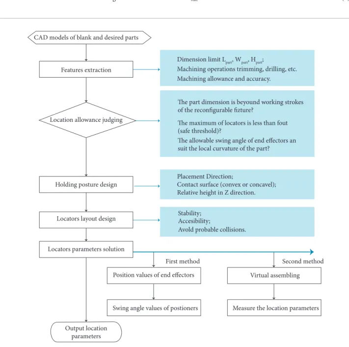
according to the dimension and shape of the surface part. he nature of location parameters solution is to transfer the aircrat skins digital model into the numerical control data, which drive the reconigurable ixture into quick and accurate reconstruction. Two diferent solution methods have been presented by the author: one is based on the geometric structures of locators and positioners (Hu et al., 2012a); another is based on the virtual locating and positioning (Hu et al., 2012b). In this paper, the standard procedure of location parameters solution is summarized as shown in Fig. 8. In a previous research by the authors (Hu et al., 2012a; Hu et al., 2012b), the procedures of holding posture design, locators layout design and location parameters solution were discussed in details. Whereas the location admissibility was omitted in previous researches, it would be described emphatically as follows.
Location admissibility indicates whether the thin shell part can be located and supported properly according to the coniguration of the reconigurable ixture and the part model. Speciically, the listed aspects should be taken into account: • he dimensions of the thin shell part are beyond the
working stroke of the reconigurable ixture?
X locators at the initial time
Gradual separation of desired shape
Gradual invalidity of Xs
locators Sustained workingof X
w locators
Figure 7. “X-2-1” location principle for thin shell parts during
lexible trimming process.
(X )–
X Y
Z 0
( Y, Z )
( ∆ ) –
~ ˆ
Figure 6. “N-2-1” location principle for deformable metal
sheet parts in drilling and welding.
he basic “3-2-1” location scheme for rigid parts may not be suitable for thin shell and compliant objects, due to their inherent lexibility and low rigidity. In such case, the ‘‘N-2-1’’ locating scheme (Fig. 6) was formally introduced for deformable sheet metal parts, as compared to the widely accepted “3-2-1” principle for rigid bodies, where N supports are required in order to support the metal sheet part in the primary datum direction to avoid excessive delection (Cai et al., 1996). It must be pointed out that the ‘‘N-2-1’’ locating scheme was presented considering that of when drilling forces or resistance spot welding forces were induced. herefore, the ‘‘N-2-1’’ location principle is appropriate when the reconigurable ixture are used for inspection, laser scribing and for the drilling process.
Nevertheless, in case of trimming process, the ‘‘N-2-1’’ locating scheme can not reveal the appearance that some locators gradually lose their efectiveness. Both the researches of Walczyk and Longtin (1999) and the initial research of the author(Hu and Li, 2011) neglected this singular detail. As illustrated in Fig. 7, at the beginning of trimming, there are X locators which take action; while with the separation of the desired shape from the blank, there are Xs locators that gradually lose their efectiveness. Until the end, only Xw locators continue to work. In short, the locators are always changing due to the workpiece separation. he author called this particular location scheme “X-2-1” location principle. “X” refers to the locators of dynamic changes. In order to guarantee the stability of the whole trimming process, designing the locators’ initial layout should take the dynamic change into account. Otherwise, the trimming operation may failure due to machining errors or other accidents.
LOCATION PARAMETERS SOLUTION
• Due to the part dimensions and the cutting trajectory, the locators that can be arranged are too few?
• he local curvature of the thin shell part is beyond the
maximum allowable swing angle of end efectors?
he irst two aspects are comparatively easy to judge and address, according to the part model and the features of the reconigurable ixture. As for the third point, when the part surface is adsorbed onto the vacuum suction of end efectors, the centre line of the end efector should be aligned to the normal
direction ni of the contact center point Pi on the locating surface.
Evidently, the center line would always be in the maximum
conical angle θmax, when the end efector swings freely to suit the
local curvature of the thin shell part. Ater the holding posture
is deined, as illustrated in Fig. 9, transfer the normal vector ni
of Pi point in the workpiece coordinate system into the normal
vector niL in the end efector coordinate system. hen igure out
the angle θ between niL and the axis Z
L If
θ≤θ
max (1)
Dimension limit Lpart, Wpart, Hpart;
Machining operations trimming, drilling, etc. Machining allowance and accuracy.
he part dimension is beyound working strokes
of the recon urable ure?
he maximum of locators is less than fout (safe threshold)?
The allowable swing angle of end effectors an suit the local curvature of the part?
Placement Direction;
Stability; Accesibility;
Avold probable collisions.
Contact surface (convex or concavel); Relative height in Z direction.
First method Second method
CAD models of blank and desired parts
Features extraction
Location allowance judging
Locators parameters solution
Output location parameters
Position values of end effectors
Swing angle values of postioners
Virtual assembling
Measure the location parameters Locators layout design
Holding posture design
the end efectors can be located at this point. Otherwise, the end effectors cannot suit the local curvature of this point. For instance, the curvature of the leading-edge skin components is oten great; thereby the free swing holding cup cannot be available. herefore, the commercially available reconigurable tooling system would generally provide a quick-change style adapter such as extension arms (Fig. 10).
For the automation of location parameters solution, a special location parameters solution sotware system (Flextrimming
system) has been improved and seamlessly integrated into the CATIA V5 sotware via the component application architecture (CAA) development kit, a component object model-like interface. he Flextrimming system can, in sequence, perform the location parameters solution procedure interactively: features extraction, locating allowance judging, holding postures design, locators layout and location parameters solution.
LOCATION ACCURACY
he geometrical accuracy of a machined feature on a workpiece depends on, partially, the ixture’s ability to precisely locate the workpiece, which is in fact related to the locator’s conigurations and positional accuracy of each locator. he reconigurable lexible, developed independently by our research group, maintains a positioning accuracy of 0.1 mm and a repeatability of 0.05 mm. On the other hand, the solution accuracy of location parameters can reach 0.1μm. Namely, the inal location accuracy depends on both the hardware and the sotware systems, and in order to validate the inal location accuracy, an aluminum alloy skin part with a thickness of 1.27 mm was selected and located on the reconigurable lexible ixture (Fig. 11). hen the located workpiece was measured using the API Tracker3 laser tracker (Fig. 12).
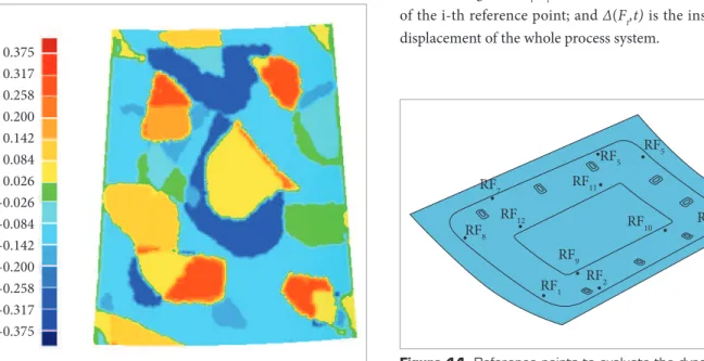
Comparative analysis between the digital model and the measurement data were performed, and the obtained error contour is shown in Fig. 13. he inal errors may be caused by the multiple efects including measurement error, forming errors and location errors. hereby errors distribution was in the reasonable scope and it can be acceptable in practical productions. Meanwhile it may be observed that there is little deformation caused by the vacuum absorption of end efectors. hough the aircrat skin is very thin and poorly rigid, its local rigidity is enough to make the end efectors swing freely to automatically adjust to the local curvatures change of the thin shell part.
DYNAMIC STIFFNESS OF THE
PROCESS SYSTEM
EVALUATION OF DYNAMIC STIFFNESS
Dynamic stifness is a measure of the machining system’s ability to dampen the vibrations from input forces, which would XL
YL ZL
Z w x
w
o
w Yw
Y F O
F
X F Z
F ni
Pi
θmax
Figure 9. Local curvature and the maximum conical angle.
directly afect machining accuracy and stability. heoretically, under the action of machining forces, the whole deformation of the
process system is caused by each individual component including the deformations of machine tool, cutter, ixture and workpiece. In fact, the thin shell part has relatively poorer stifness, thus the deformation of thin shell part is the largest part of the whole deformation of the process system. herefore, other deformations are neglected and only the workpiece deformation is considered. As previously mentioned, the surface part can be regarded as the constitution of discrete points. hen the points close to end efectors could be fully restricted and the displacements of other points would vibrate along with the trimming process. Obviously, the closer the point is to the vacuum adsorption area, the less its vibration will be. Conversely, the farther the point is to the cutting path, the greater its vibration will be. In order to evaluate the dynamic stifness of the whole ixturing system, n points near to the cutting paths was selected evenly from nodes on the elements as reference points (Fig. 14) and the dynamic stifness is deined as follows,
1 Kt (F
t,t)
Ft
∆
= = 1
k1t+1k2t+ . . . +1knt
(2)
( , t
i it
F F t
k
δ t )= (3)
(Ft,t)=δ1(F,t)+δ2(F,t)+ . . . +δn(F,t)
∆ (4)
Where Ft denotes the external loads, and the subscript t is
the trimming time; δi(Ft, t ) is the instantaneous displacement
of the i-th reference point; and Δ (F t, t ) is the instantaneous
displacement of the whole process system.
Figure 11. Locating set-up.
Figure 12. Measurement via laser tracker.
0.375
0.317
0.258
0.200
0.142
0.084
0.026
-0.026
-0.084
-0.142
-0.200
-0.258
-0.317
-0.375
Figure 13. Error distribution contour.
R F7
R F8
R F1 R F2
R F3 R F4 R F5
R F5
R F9
R F10 R F11
R F12
Figure 14. Reference points to evaluate the dynamic
EFFECTS OF LOCATION LAYOUT ON DYNAMIC STIFFNESS
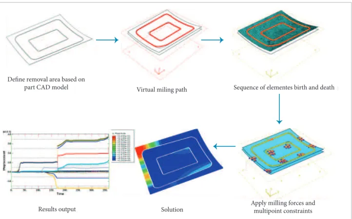
In order to analyze the effects of location layout on the dynamic stiffness, the finite element simulation was performed using the specially developed system for the lexible
trimming process (Hu et al., 2012b).he basic principle is
to sequentially “kill” the elements on the trimming paths in order to simulate the separation process of the desired part. Meanwhile, the milling forces are loaded on the elements that would be “killed” in the next step. As regards the milling
Define removal area based on
part CAD model Virtual miling path Sequence of elementes birth and death
Apply milling forces and multipoint constraints Solution
Results output
Figure 15. Simulation procedure for trimming process.
Table 1. Location layout mm.
Layout No. x1 x2 x3 y11 y12 y13 y21 y22 y23 y31 y32 y33
1# 169 579 1112 39 4 8 1 8 5 5 175 5 8 3 9 9 1 3 9 4 8 1 923
2# 46 579 1030 141 617 991 39 447 991 175 549 991
3# 46 456 1153 107 515 923 141 515 957 39 4 8 1 9 2 3
4 # 3 9 4 8 1 9 2 3 1 7 5 5 4 9 9 2 3 3 9 4 8 1 9 9 1 39 447 991
5# 128 661 1112 141 583 991 73 617 991 39 549 957
forces magnitude, the proposed method (Hu and Li, 2012) was employed. Hereby, the displacements of the reference points can be solved dynamically. he whole procedure is illustrated in Fig. 15.
Cliff effect
Cliff effect
Time/s
Time/s Layout 1
0.05
0.04
0.03
0.02
∆(F
t,t)/mm
0.01
0.00
Layout 2 Layout 3 Layout 4 Layout 5
0. 50. 100. 150. 200. 250. 300. 350.
Layout 1 0.020
0.015
0.010
∆(F
t,t)/mm
0.005
0.000
Layout 2 Layout 3 Layout 4 Layout 5
0. 50. 100. 150. 200. 250. 300. 350.
Cliff effect
Time/s Layout 1
[x1.E-3]
8.0
6.0
4.0
2.0
0.0
∆(F
t,t)/mm
Layout 2 Layout 3 Layout 4 Layout 5
0. 50. 100. 150. 200. 250. 300. 350.
(c) (b) (a)
Figure 16. Simulation procedure for trimming process. Cutting parameters: (a) n = 10000 r/min, aP= 1.27 mm,
REFERENCES
Boyle, I., Rong, Y. and Brown, D.C., 2011, “A Review and Analysis of Current Computer-Aided Fixture Design Approaches”, Robotics and Computer-Integrated Manufacturing, Vol. 27, No. 1, pp. 1-12. doi: 10.1016/j.rcim.2010.05.008.
Cai, W., Hu, S.J. and Yuan, J.X., 1996, “Deformable Sheet Metal Fixturing: Principles, Algorithms, and Simulations”, Journal of Mechanical Design, Vol. 118, No. 3, pp. 318-324. doi: 10.1115/1.2831031.
From the inite element situation results (Fig. 16), it was quite easy to tell that the irst and ith layouts were the best arrangements
when compared to the other three layouts. he symbols n , ap and
fZ, respectively, denote the speed of spindle, the part thickness and
the feed per tooth. he good location layout could maintain the dynamic stifness along with the trimming time. Especially, with the decreasing of the part thickness, the location layout has an increasing efect on the dynamic stifness of the whole process system.
Another noticeable appearance, as marked in the Fig. 16, should not be ignored, i.e., the clif efect of the instantaneous displacement of the reference nodes. In the case, the dynamic stifness of the ixturing system would drop suddenly, due to some locator, becoming valid. At this time, dramatic vibrations may occur and the machining error would be induced. With the decrease of the part thickness, the efect of layout on the dynamic stifness would increase. However, the efect of layout on the time of the clif efect occurrence may not be obvious. If the location layout was designed properly, the clif efect could be restrained within narrow limits, such as the irst and ith layouts.
herefore, when planning the location layout, the clif efect case should be avoided.
CONCLUSIONS
he numerical control trimming process for aircrat skins in the reconigurable ixture is a digital and lexible fabrication technology. However, due to the multi-point location, low rigidity of thin shell part and the ongoing separation of desired contours, this promising technology becomes a knotty operation to guarantee good workpiece-holding stability and machining accuracy. his paper mainly contributes to the following issues:
• he unique location schema, namely the “X-2-1” location
principle, was revealed in view of the gradual reduction of
efective locators of the reconigurable ixture during trimming process. his work may perfect the location principles of low rigidity parts. Meanwhile, the “discrete points” model of thin shell parts was introduced; thereby it would help to igure out the nature of thin shell part location (i.e., to restrict the degrees of freedom of the discrete mass points) and the quantitative evaluation for the dynamic stifness of the ixturing system (i.e., to calculate the displatments of the referred nodes).
• he location parameters solution method was further
summarized. Especially, the location admissibility was mainly presented; this work improved the location design procedure. In addition, the location accuracy was discussed through a locating experiment in order to validate the location parameters solution accuracy as well as the positional accuracy of the reconigurable ixture.
• A quantitative evaluation method of the dynamic
stifness of the ixturing system was put forward. his work provided a criterion for the quantitative analysis of location layout. Moreover, the efects of location layout on the dynamic stifness of the lexible ixturing system were analyzed using the inite element simulation system for the trimming process. Noticeably, the clif efect of the dynamic stifness can be observed from the simulation results. his case should be alleviated or avoided through the optimization of location layout.
ACKNOWLEDGEMENTS
Cai, Z.Y., Wang, S.H., Xu, X.D. and Li, M.Z., 2009, “Numerical Simulation for the Multi-Point Stretch Forming Process of Sheet Metal”, Journal of Materials Processing Technology, Vol. 209, No. 1, pp. 396-407. doi: 10.1016/j.jmatprotec.2008.02.010.
Cecil J., 2001, “Computer-Aided Fixture Design – a Review and Future Trends”, The International Journal of Advanced Manufacturing Technology, Vol. 18, No. 11, pp. 790-793. doi: 10.1007/s001700170004.
Chen, L., 2006, “Research and Key Techniques on the Establishment of Reconigurable Flexible Stretch-Formed Die”, Beihang University, Beijing, China.
Cui, X., Xu, X., Li, G., Li, M. and Cai, Z., 2008, “Development and Application of the Multi-Point Stretch-Forming Equipment for Aircraft Skins”, China Metal forming Equipment & Manufacturing Technology, Vol. 43, No. 3, pp. 35-37. doi: 10.3969/j.issn.1672-0121.2008.03.011.
Douglas, W.A. and Ozer, T., 1987, “Universal Holding Fixture”, U.S.A patents 4684113.
Hardt, D.E., Olson, B.A., Allison, B.T. and Pasch, K., 1981, “Sheet Metal Forming With Discrete Die Surfaces”, Ninth North American Manufacturing Research Conference Proceedings, pp. 140–144.
Hu, F. and Li D., 2011, “Process Planning and Simulation Strategies for Perimeter Milling of Thin-Walled Flexible Parts Held by Reconigurable Fixturing System”, IEEE 2011 Third International Conference on Measuring Technology and Mechatronics Automation, Vol. 2, pp. 922-926. doi: 10.1109/ICMTMA.2011.513.
Hu, F. and Li D., 2012, “Modelling and Simulation of Milling Forces Using an Arbitrary Lagrangian–Eulerian Finite Element Method and Support Vector Regression”, Journal of Optimization Theory and Applications, Vol. 153, No. 2, pp. 461-484. doi: 10.1007/s10957-011-9927-y.
Hu, F., Li, D., Li, X. and Zhu, M., 2012a, “Locating Simulation for Aircraft Skins NC Trimming Based on Flexible Holding Fixture”, Computer Integrated Manufacturing Systems, Vol. 18, pp. 993-998.
Hu, F., Li, D., Li, X. and Zhu, M., 2012b, “Process Planning of Aircraft Skins NC Trimming Based on Reconigurable Fixture”, Journal of Beijing University of Aeronautics and Astronautics, Vol. 38, pp. 675-680.
Huang, L., Li, D. and Luo, H., 2008, “Research on Closed-Loop Shape Control System of Stretch Forming Over Reconigurable Tooling”, Journal of Plasticity Engineering, Vol. 15, No. 6, pp. 38-42.
Koelsch, J.R., 1998, “Hold It”, Machine Shop Guide, Vol. 3, pp. 26-33.
Li, D., Luo, H., Wang, L. and Li, X., 2009, “Numerical Forming Technology of the Aircraft Skin”, Journal of Plasticity Engineering, Vol. 16, pp. 61-65.
Munro, C. and Walczyk, D., 2007, “Reconfigurable Pin-Type Tooling: a Survey of Prior Art and Reduction to Practice”, Journal of Manufacturing Science and Engineering, Vol. 129, No. 3, pp. 551-565. doi: 10.1115/1.2714577.
Papazian, J.M., Anagnostou, E.L., Christ, R.J., Hoitsma, Jr.D., Ogilvie, P. and Schwarz, R.C., 2002, “Tooling for rapid sheet metal parts production”, 6th Joint FAA/DoD/NASA Conference on Aging Aircraft, San Francisco, CA,USA.
Proctor, P., 1998, “Pogo Fixtures Enhance Tooling Flexibility”, Aviation Week & Space Technology, Vol. 149, No. 8, pp. 50-51.
Riveiro, A., Quintero, F., Lusquiños, F., Pou, J. and Pérez-Amor, M., 2008, “Laser Cutting of 2024-T3 Aeronautic Aluminum Alloy”, Journal of Laser Applications, Vol. 20, pp. 225-230. doi: 10.2351/1.2995769.
Sela, M.N., Gaudry, O., Dombre, E. and Benhabib, B., 1997, “A Reconigurable Modular Fixturing System for Thin-Walled Flexible Objects”, The International Journal of Advanced Manufacturing Technology, Vo1. 13, No. 9, pp. 611-617. doi: 10.1007/ BF01350819.
Shirinzadeh, B., 2002, “Flexible Fixturing for Workpiece Positioning and Constraining”, Assembly Automation,Vol. 22, No. 2, pp. 112-120. doi: 10.1108/01445150210423143.
Walczyk, D.F. and Hardt, D.E., 1998, “Design and Analysis of Reconigurable Discrete Dies for Sheet Metal Forming”, Journal of Manufacturing Systems, Vol. 17, No. 6, pp. 436-454. doi: 10.1016/ S0278-6125(99)80003-X.
Walczyk, D.F. and Longtin, R.S., 1999, “Fixturing of Compliant Parts Using a Matrix of Reconigurable Pins”, Journal of Manufacturing Science and Engineering-transactions of The Asme, Vol. 122, No. 4, pp. 766-772. doi: 10.1115/1.1314599.
Wang, H., Rong, Y.K., Li, H. and Shaun, P., 2010, “Computer Aided Fixture Design: Recent Research And Trends”, Computer-Aided Design, Vol. 42, No. 12, pp. 1085-1094. doi: 10.1016/j.cad.2010.07.003.
Youcef-Toumi, K., Liu, W.S. and Asada H., 1987, “A Computer Integration of Reconigurable Fixtures and Drilling of Sheet Metal Parts”, Robotics and Factories of the Future ’87, Proceedings of the 2nd International Conference San Diego, California, pp. 751-759. doi: 10.1007/978-3-642-73890-6_90.
Yu, C., Li, D. and Li, X., 2011, “Application of the Preprocessing System of Stretch Forming Over Multi-Point Tooling in Real Factory Environment”, Advanced Science Letters, Vol. 4, No. 6-7, pp. 2396-2399. doi: 10.1166/ asl.2011.1457.
Zhou, C., Cai, Z. and Li, M., 2005, “Stretching Process Based on Multi-Point Die and Its Numerical Simulation”, Journal of Jilin University of Technology (Natural Science Edition), Vol. 35, pp. 287-291.
Zhou, F., 2007, “A New Generation Multi-Point Flexible Tooling for Aircraft Skin Stretch Forming”, Aeronautical Manufacturing Technology, Vol. 11, pp. 30-33.