ABSTRACT: For a small country with limited research budget and lack of advanced space technology, it is imperative to ind new approaches for the development of low-cost launch vehicles (LV), which is, among all possibilities, an interesting option for rapid access to space, focused on integration of acquired components complemented with indigenously developed subsystems. This approach requires the cooperation of developed countries with huge experience and knowledge in LV development and operations. The main objective is to develop a small three stage solid propellant LV capable of delivering a payload of 100 kg to a circular low earth orbit of 600 km altitude, with the irst and second stage solid rocket motors (SRM) hypothetically acquired from different countries and the third one designed and produced domestically in accordance with the production and technological capability. This approach provides main advantages such as: reduction in total time to access the space and to master the basic knowledge of launch operations. For this purpose, an integer continuous genetic algorithm global optimization method was selected and implemented, the SRM characteristics of the irst and second stage were considered as integer variables, whereas the design variables of the third stage SRM and the trajectory variable were considered as continuous. A multi discipline feasible (MDF) framework was implemented along with the propulsion, aerodynamic, mass and trajectory models. Despite their particular characteristics and constraints, the results show highly acceptable values, and the approach proved to be reliable for conceptual design level.
KEYWORDS: Launch vehicle, Mixed design optimization, Solid propellant.
Small Solid Propellant Launch Vehicle
Mixed Design Optimization Approach
Fredy Marcell Villanueva1, He Linshu1, Xu Dajun1
INTRODUCTION
he last decade may be characterized by an increased number of small satellites delivered into the low earth orbit (LEO), and this tendency will be dominant in the coming years.
Small satellites have a reduced manufacturing cost, and are relatively easy to operate and maintain. Furthermore, the miniaturization of technology makes possible its delivery into space by using small cost efective launch vehicles (LV).
Small countries generally have a limited research budget oriented to space technology development, however, nowadays it is possible to deliver a small satellite into orbit with a reasonable budget, considering the cooperation with technologically more advanced countries.
his research was focused on inding a way to have rapid access into space and to master the basic knowledge of space development and operations. In such a way, several options had been analyzed, among them the most suitable alternative in terms of economic investment and development time resulted in a small solid propellant LV with mixed design coniguration, involving a strong cooperation with diferent countries.
he strategy considered here prioritizes the technology integration over expensive and time consuming new development, this means that complex and advanced devices were acquired and complemented with indigenous manufactured devices using available resources and technology.
As a result, a three stage solid propellant LV was conigured, where the irst and second stage solid rocket motors (SRM) were acquired from diferent providers, complemented with a locally developed third stage SRM, which was designed and optimized to accomplish the speciic mission.
1.School of Astronautics – Beihang University – Beijing – China
Author for correspondence: Fredy Marcell Villanueva | Beihang University | School of Astronautics | Haidian District, 37 Xueyuan Road – New Main Building, B923 | Beijing 100191 – China | Email: marcell385@ yahoo.com
In our research, a mixed integer continuous variables genetic algorithm (GA) method has been used in order to optimize the overall coni guration of the LV.
LAUNCH VEHICLE MODEL
LAUnCh VEhiCLE DEFiniTiOn
A small three stage solid propellant LV in tandem coni guration is considered for this research. h e mission is to deliver a 100 kg payload to a circular LEO of 600 km of altitude. h e payload volume requirements and the instrument module weight were specii ed beforehand in mission dei nition analysis and are shown in Table 1.
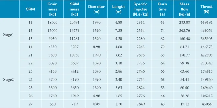
COnSiDERED SOLiD ROCKET mOTORS
h e considered SRM are listed in the Table 2 and were selected based on the variety of design characteristics. However, it is possible to add additional parameters such as cost, availability, technology complexity, country of origin among others.
pROpULSiOn AnALYSiS
h e propulsion analysis has been conducted for all three stages of the LV, using the classical approach presented in Sutton and Biblarz (2001) and He (2004a; 2004b). For the third stage SRM, a detailed analysis was conducted, considering the properties of the propellant. In this analysis, the burning surface is considered constant by introducing a grain geometry shape coeffi cient, ks , the burning surface of the grain Sb can be calculated as:
(1)
where, Lm is the rocket motor cylindrical length and Dm the diameter.
h e burning time tb, grain mass mgn, and mass l ow rate mgn of the grain are calculated as:
(2)
Variables Units Value
Payload kg 100
Fairing mass kg 50
Instrument module kg 50
Payload deployment module kg 50
Table 1. Launch Vehicle data.
SRm
Grain mass
(kg)
SRm mass (kg)
Diameter (m)
Length (m)
Specii c impulse (n.s/kg)
Burn time
(s)
mass l ow (kg/s)
Thrust (n)
Stage1
11 18400 20791 1990 4.80 2364 65 283.08 669194
12 15000 16779 1390 7.25 2314 74 202.70 469054
13 9950 11281 1390 5.20 2280 62 160.48 365903
14 4530 5207 0.98 4.60 2265 70 64.71 146578
Stage2
21 9800 10950 1990 3.62 2805 65 150.77 422908
22 5080 5607 1390 3.10 2776 64 79.38 220345
23 4138 4412 1390 2.86 2746 65 63.66 174815
24 3700 4190 1390 2.40 2754 68 54.41 149850
25 3300 3650 1390 2.63 2824 55 60.00 169440
26 1760 1949 0.98 1.85 2776 46 38.26 106212
27 650 719 0.85 1.50 2849 43 15.12 43066
Table 2. Selected solid rocket motors.
(3)
(4)
(5)
where, u is the burning rate of propellant, ρgn density of the grain, Lgn = Lm + 0.314Dm length of the grain, Dgn = Dm diameter of the grain, λgn i neness ratio of the grain (grain length/diameter), and ηv the grain volumetric loading fraction.
h e expansion ratio ε, nozzle throat area At, and nozzle exit area Ae are calculated as:
(6)
(7)
(8)
(9)
where, Pc is the chamber pressure, pe exit pressure, Rc = 296 J/(kg.K) gas constant, Tc = 3300 K temperature in the combustion chamber, Pc max = 1.1Pc maximum value of chamber pressure, and k = 1.2 the specii c heat ratio of gas.
h e specii c impulse Isp, and the thrust T can be calculated as:
(10)
(11)
where, pa is the atmospheric pressure, Ia
sp average specific
impulse, g acceleration due to gravity, and Ae the nozzle exit area.
mASS AnALYSiS
h e mass analysis was conducted for the entire LV, and is represented by the following equations:
(12)
(13)
(14)
where, mLV is the LV gross mass, m01 i rst stage mass, m02 second stage mass, m03 third stage solid rocket mass, mIM instrument module mass, mPDM payload deployment module mass, mPAY payload mass, and mstthe structural mass of the third stage SRM.
He (2004a; 2004b) provided a methodology and a detailed calculation of the third stage SRM structural mass. h is design consisted in a classical metallic case made of high strength steel, ethylene propylene diene monomer (EPDM) for chamber insulation, and carbon phenolic for the nozzle.
AERODYnAmiC AnALYSiS
h e aerodynamic coeffi cients were estimated using the Missile DATCOM 1997 digital (Blake, 1998). h is sot ware is easy to use and implemented, and accurate enough for the conceptual design phase. Qazi and He (2005) and Villanueva et al. (2013) applied DATCOM in LV aerodynamics analysis. h e lit and drag forces were calculated using the following relations:
(15)
(16)
where, q is the dynamic pressure, D drag force, L lit force, Sref vehicle reference area, CL lit coeffi cient, and CD the drag coeffi cient. h e aerodynamic coeffi cients were calculated repeatedly for each LV coni guration, the selected Mach ranged from 0 to 8 and the angle of attack from −8 to +1 degrees.
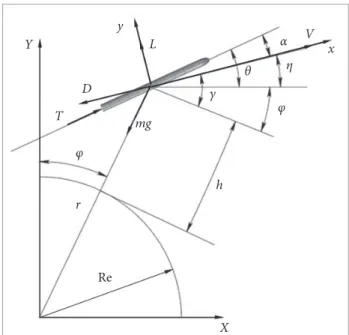
TRAJECTORY AnALYSiS
its origin located in the center of the earth. Furthermore, all forces applied to the LV were considered in relation to the body centered velocity coordinate systems xoy as shown in Fig. 1.
(17)
where, V is the velocity, m vehicle mass, θ pitch angle, η t rajectory angle, γ flight path angle, φ range angle, h height above ground, α angle of attack, and αprog (t) is the programmed angle of attack.
The axial and normal overload coefficients ensure the integrity of the LV in all phases of l ight, and were calculated in a body centered velocity coordinate systems (xoy), as follows:
(18)
(19) The thrust to weight ratio gives an importan t value to evaluate the lit of characteristics of the LV:
(20)
h e density variation with altitude can be calculated as:
(21)
h e gravity varies with altitude and can be represented as:
(22)
where, ρ0 is the sea level density, Re radius of earth, β density scale height, and μ the earth gravitational parameter.
h e mission requires to deliver the payload to an altitude hf with a circular orbital insertion velocity Vf:
(23)
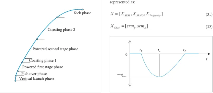
TRAJECTORY phASES
h e trajectory of the LV can be described as a composition of several phases, as presented by He (2004a), Qazi and He (2005) and Villanueva et al. (2013). For the present research, the trajectory was sectioned in seven phases, as shown in Fig. 2. Each phase has a specii c l ight characteristic as described next: • Vertical launch phase: h is phase starts from the time of
ignition of the i rst stage SRM until the end of vertical l ight time tv (tv = t1 in Fig. 3), during this time the LV l ies vertically with a l ight path angle equal to 90 degrees. • Pitch over phase: During this phase, the LV maneuver with a
negative angle of attack until the transonic velocity is reached. In this point, the angle of attack should approaches zero degrees. • Powered i rst stage phase: h is phase lasts until the end of
the burning time of the i rst stage SRM. h e angle of attack should be kept at zero during the stage separation process. • Coasting phase 1: h e LV l ies with no thrust until the
second stage ignites.
• Powered second stage phase: h e duration of this phase starts with the ignition of the second stage SRM and is equal to its burning time.
y L
Re
V x α
γ
φ θ
φ
η
D Y
X
T mg
h r
• C o a s t i n g p h a s e 2: h is phase is characterized by a prolonged ballistic free l ight approaching the target altitude. • Kick phase: h is phase starts with the ignition of the third
stage SRM until the insertion altitude at the required orbital velocity and l ight path angle.
FLiGhT pROGRAm FORmULATiOn
h e l ight proi le dei nes the performance and loads acting on the LV Consequently, its selection should be integrated in the optimization process. Figure 3 explains the variation of the angle of attack during the pitch over phase (He, 2004a; Xiao, 2001):
(24)
(25)
(26)
where,
max is the maximum angle of attack, am launch maneuver variable, ta time corresponding to maximum angle of attack, t time of l ight, and t1 the time of start of pitch over phase, coincident in value with time tv.
DESIGN OPTIMIZATION PROBLEM
OBJECTi VE FUnCTiOn
h ere can be dif erent objective functions for LV optimization problem, such as minimization of the LV cost, which can be obtained knowing the cost of the i rst and second stage SRMs and the development cost of the third stage, and also the minimization of the development time, knowing the availability of the i rst and second stage SRM and the development time of the third stage SRM. However, this analysis considers the minimization of the gross launch mass (mLV). h e mathematical description of design objective is as follows:
(27)
(28)
(29)
(30)
where, gj is the inequality constraints, hk the equality constraints, X the set of variables, Xlb the lower bound of variables and Xub the upper bound of variables.
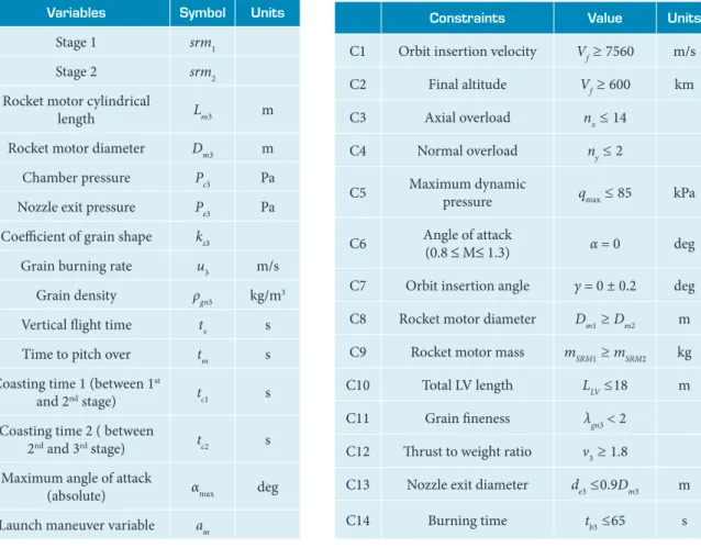
DESiGn VARiABLES
The design variables are composed from integer (first and second stage SRMs), and continuous third s tage SRM and trajectory variables. h ey are listed in Table 3 and can be represented as:
(31)
(32)
Vertical launch phase Powered first stage phase
Powered second stage phase
Coasting phase 1
Coasting phase 2
Kick phase
Pich over phase
Figure 2. Trajectory phases of launch vehicle.
α
− max α −
t
t1 ta t2
0
(33)
(34)
DESiGn COnSTRAinTS
The selections of constraints were oriented in order to satisfy the mission, to prevent any failure during l ight, and to consider the limitation of the third stage manufacturing technology. h ey are listed in Table 4:
OPTIMIZATION STRATEGY
inTEGER COnTinUOUS OpTimizATiOn AppROACh
h e particularity of our problem deals with integer and continuous variables simultaneously. h e selection of SRM type for i rst and second stages were considered as integer variables.
Meanwhile, the trajectory and design parameters of the third stage SRM were considered as continuous.
Several engineering applications of mixed integer continuous optimization approach were presented by Haupt et al. (2009), Faustino et al. (2006), as well as detailed explanation in Yeniay (2005) and Gantovnik et al. (2005).
Gari eld and Allen (1995) used integer optimization applied to the configuration of LVs, Johnson (2002) conducted a screening process of booster for hypersonic vehicles, Calabro et al. (2002) presented the optimization of the propulsion for multistage LVs, and Bhatnagar et al. (2012) solved the mass distribution problem under restrictive condition.
Harti eld et al. (2004) have shown the application of GA in i nding the global optimum in ramjet propulsion. Bayley and Harti eld (2007) used GA for LV multidisciplinary design optimization with emphasis on minimum cost.
GA has been ef ectively applied to solve the problem of liquid propellant based LV (Riddle et al. 2007), as well as
Variables Symbol Units
X1 Stage 1 srm1
X2 Stage 2 srm2
X3 Rocket motor cylindrical
length Lm3 m
X4 Rocket motor diameter Dm3 m
X5 Chamber pressure Pc3 Pa
X6 Nozzle exit pressure Pe3 Pa
X7 Coeffi cient of grain shape ks3
X8 Grain burning rate u3 m/s
X9 Grain density ρgn3 kg/m3
X10 Vertical l ight time tv s
X11 Time to pitch over tm s
X12 Coasting time 1 (between 1
st
and 2nd stage) tc1 s
X13 Coasting time 2 ( between
2nd and 3rd stage) tc2 s
X14 Maximum angle of attack
(absolute) αmax deg
X15 Launch maneuver variable am
Table 3. Design variables.
Constraints Value Units
C1 Orbit insertion velocity Vf ≥ 7560 m/s
C2 Final altitude Vf ≥ 600 km
C3 Axial overload nx≤ 14
C4 Normal overload ny≤ 2
C5 Maximum dynamic
pressure qmax≤ 85 kPa
C6 Angle of attack
(0.8 ≤ M≤ 1.3) = 0 deg
C7 Orbit insertion angle 0 ± 0.2 deg
C8 Rocket motor diameter Dm1≥Dm2 m
C9 Rocket motor mass mSRM1≥mSRM2 kg
C10 Total LV length LLV≤18 m
C11 Grain i neness λgn3 < 2
C12 h rust to weight ratio v3 ≥ 1.8
C13 Nozzle exit diameter de3 ≤0.9Dm3 m
C14 Burning time tb3 ≤65 s
solid propellant LVs (Bayley et al. 2008). Raique et al. (2009) and Goldberg (1989) provides detailed and comprehensive implementation of GA in solving complex problems.
OpTimizATiOn mEThOD
The adopted and implemented GA optimization method is shown in Fig. 4, where a set of input design variables (SRM type, trajectory and third stage), as well as the lower and upper bounds, are passed to the main loop, where an initial population is randomly created. Furthermore, the selection, the crossover and the mutation operations are performed until the stopping criteria is achieved. The constraints
were calculated and handled by external penalty function, as presented in Deb (2000) and detailed and explained in Coello (1999) and Kramer (2010). At each routine, the propulsion, mass, aerodynamics and trajectory analysis were performed.
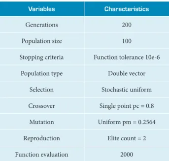
he main characteristics of GA are presented in Table 5.
OpTimizATiOn FRAmEWORK
he optimization framework considered for this research is based on the multi-discipline feasible (MDF) design, which allows an easy and accurate result (Qazi and He L, 2006), as shown in Fig. 5.
P opulation initialization
Stopping criteria Selection
Crossover
Mutation Design Variables
Optimal Solution Yes No
Mass analysis Propulsion
analysis
Aerodynamic analysis
Trajectory analysis Multidisciplinary
Design Analysis
Figure 4. Genetic algorithm optimization approach.
Table 5. Genetic algorithm characteristics.
Variables Characteristics
Generations 200
Population size 100
Stopping criteria Function tolerance 10e-6
Population type Double vector
Selection Stochastic uniform
Crossover Single point pc = 0.8
Mutation Uniform pm = 0.2564
Reproduction Elite count = 2
Function evaluation 2000
Vehicle Definition
Propulsion Analysis
Mass Analysis
Trajectory Analysis Aerodynamic
Analysis
•Fairing Configuration
Optimal Design • Thrust
•Burning
Time ••MachAltitude
•Vehicle Size Design Variables
•Lift
•Drag
•Stage mass
•Stage dimensions
•Vehicle Performance
Figure 6. Optimized three stage launch vehicle.
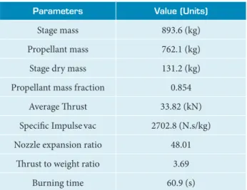
Table 7. Parameters of launch vehicle third stage.
parameters Value (Units)
S tage mass 893.6 (kg)
Propellant mass 762.1 (kg)
Stage dry mass 131.2 (kg)
Propellant mass fraction 0.854
Average h rust 33.82 (kN)
Specii c Impulsevac 2702.8 (N.s/kg)
Nozzle expansion ratio 48.01
h rust to weight ratio 3.69
Burning time 60.9 (s)
OPTIMIZATION RESULT
The results show that the considered mixed integer-continuous GA optimization approach successfully reached the objective function. h e optimized LV has a total mass of 23,530 kg and a 16.12 m of length. Table 6 shows the optimized value of variables and in Table 7 the main parameters of the LV third stage are listed.
The first and second stages SRM design type (SRM 12 and SRM 22), had been optimized and selected from Table 2. Both SRMs have the same diameter but dif erent length. As it is represented in Fig. 6, the shroud design is coni gured with the same diameter as the third stage, in order to reduce the aerodynamics forces and interferences.
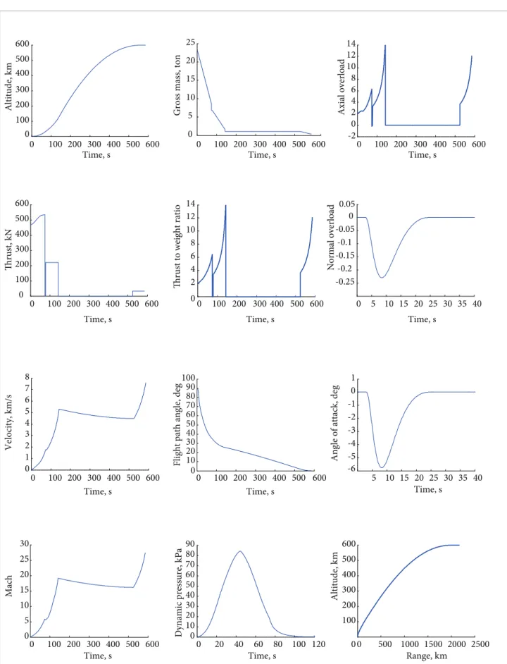
The performance characteristics of the LV, shown in Fig. 7, demonstrates the capability of the three stage solid propellant LV to place a small payload into the LEO orbit maintaining its main parameters inside its limit values, furthermore, the overall design configuration facilitates its launch operations.
CONCLUSION
A small three-stage solid propellant LV was coni gured and optimized using a mixed integer-continuous GA optimization method. h e i rst and second stages SRM types were considered as integer variables, whereas the third stage SRM and trajectory as continuous. h e main advantage of using GA relies on its independency of initial values to start the optimization, and the ability to handle integer variables. h e propulsion, mass, aerodynamic and dynamic models were developed and integrated in a MDF framework.
Variables Lower
Bound
Upper Bound
Optimized Value
X1 srm1 11 14 12
X2 srm2 21 27 22
X3 Lm3 (m) 0.80 1.20 0.90
X4 Dm3 (m) 0.80 1.20 0.83
X5 Pc3 (Pa) 70e5 80e5 77.42e5
X6 Pe3 (Pa) 0.05e5 0.15e5 0.133e5
X7 ks3 1.10 1.60 1.14
X8 u3 (m/s) 6.0e-3 8.0e-3 6.71e-3
X9 ρgn3 (kg/m3) 1650 1740 1683.1
X10 tv (s) 3.0 6.0 3.01
X11 tm (s) 18.0 25.0 21.57
X12 tc1 (s) 2.0 8.0 4.46
X13 tc2 (s) 360 400 372.61
X14 αmax (deg) 3.0 6.0 5.731
X15 am 0.28 0.42 0.319
100 200 300 400 500 600 0 0 100 200 300 500 400 600 Time, s A lt it u d e, k m
0 100 200 300 400 500 600 0 100 200 300 400 500 600 Th ru st , k N Th ru st
to weight ratio
0 100 200 300 400 500 600 0 1 2 3 4 5 6 7 8 Velo city , k m /s
Flight path angle, deg
0 100 200 300 400 500 600 0 5 10 15 20 25 30 M ach
0 100 200 300 400 500 600 0 5 10 15 20 25 Time, s Gr o ss m as s, to n
0 100 200 300 400 500 600 0 2 4 6 8 10 12 14 Time, s Time, s Time, s Time, s Time, s
0 100 200 300 400 500 600 0 10 20 30 40 50 60 70 80 90 100
0 20 40 60 80 100 120 0 10 20 30 40 50 60 70 80 90 Time, s Dy n am ic p res su re , k Pa
0 100 200 300 400 500 600 0 2 -2 4 6 8 10 12 14 Time, s Ax ial o ver lo ad
0 5 10 15 20 25 30 35 40 -0.25 -0.2 -0.15 -0.1 -0.05 0 0.05 Time, s No rm al o ver lo ad
5 10 15 20 25 30 35 40 -5 -6 -4 -3 -2 -1 0 1 Time, s
0 500 1000 1500 2000 2500 0 100 200 300 400 500 600 Range, km Altitu d e, k m
Angle of attack, deg
REFERENCES
Bayley, D.J. and Hartield, R.J., 2007, “Design Optimization of a Space Launch Vehicles for Minimum Cost Using a Genetic Algorithm”, AIAA 43rd AIAA/ASME/SAE/ASEE Joint Propulsion Conference and Exhibit, AIAA 2007-5852.
Bayley, D.J., Hartield, R.J., Burkhalter, J.E. and Jenkins R.M., 2008, “Design Optimization of a Space Launch Vehicle Using a Genetic Algorithm”, Journal of Spacecrafts and Rockets, Vol. 45, No. 4, pp. 733–740.
Bhatnagar, P., Rajan, S. and Saxena, D., 2012, “Study on Optimization Problem of Propellant Mass Distribution Under Restrictive Condition in Multistage Rocket”, International Conference on Advances in Computer Applications (ICACA), No. 1, pp. 27-29.
Blake, W.B., 1998, “Missile DATCOM: User’s Manual-1997 FORTRAN 90 Revision”, Wright-Patterson AFB, Oklahoma.
Calabro, M., Dufour, A. and Macaire, A., 2002, “Optimization of the Propulsion of Multistage Solid Rocket Motor Launcher”, Acta Astronautica, Vol. 50, No. 4, pp. 201–208. doi: 10.1016/S0094-5765(01)00164-3.
Coello, C.A., 1999, “A Survey of Constraint Handling Techniques Used with Evolutionary Algorithm”, Technical Report Lania-RI-99-04, Laboratorio Nacional de Informatica Avanzada, Rebamen 80, Xalapa, Veracruz 91090, Mexico.
Deb, K., 2000, “An Eficient Constraint Handling Method for Genetic Algorithm”, Computer Methods in Applied Mechanics and Engineering, Vol. 186, No. 2-4, pp.311-338. doi: 10.1016/S0045-7825(99)00389-8.
Faustino, A.M., Judice, J.J., Ribeiro, I.M. and Neves, A.S., 2006, “An Integer Programming Model for Truss Topology Optimization”, Investigação Operacional, Vol. 26, No. 1, pp. 111-127.
Fleeman, E.L., 2001, “Tactical Missile Design”, AIAA, Reston.
Gantovnik, V.B., Gurdal, Z., Watson, L.T. and Anderson-Cook, C.M., 2005, “Genetic Algorithm for Mixed Nonlinear Programming Problems Using Separate Constraint Approximations”, 31st AIAA Journal, Vol. 43, No. 8, pp. 1844-1849.
Garield, J.R. and Allen, B.D., 1995, “Screening Studies and Techniques for All-Solids Space Launch Vehicles”, 31st AIAA/ASME/ SAE/ASEE Joint Propulsion Conference and Exhibit.
Goldberg, D.E., 1989, “Genetic Algorithms in Search, Optimization, and Machine Learning”, Addison-Wesley.
Hartield, R.J., Jenkins, R.M. and Burkhalter, J.E., 2004, “Ramjet Powered missile design using a genetic algorithm”, 42nd AIAA Aerospace Sciences Meeting and Exhibit, AIAA 2004-0451.
Haupt, S.E., Haupt, R.I. and Young, G.S., 2011, “A Mixed Genetic Algorithm Used in Biological and Chemical Defense Applications”, Software and Computing, Vol. 15, pp. 51-59. doi: 10.1007/s00500-009-0516-z.
He, L., 2004a, “Launch Vehicle Design”, Beijing University of Aeronautics and Astronautics Press, Beijing.
He, L., 2004b, “Solid Ballistic Missile Design”, Beijing University of Aeronautics and Astronautics Press, Beijing.
Johnson, D.B., 2002, “Screening Process for Boosters for Hypersonic Vehicles”, AIAA/AAAF 11th International Space Plane and Hypersonic Systems and technologies, AIAA 2002-5218.
Kramer, O., 2010, “A Review of Constraint-handling Techniques for Evolution Strategies”, Applied Computational Intelligence and Soft Computing, Vol. 2010, Article ID 185063, pp. 11. doi: 10.1155/2010/185063.
Qazi, M. and He, L., 2005, ““Rapid Trajectory Optimization Using Computational Intelligence for Guidance and Conceptual Design of Multistage Space Launch Vehicle”, AIAA Guidance, Navigation, and Control Conference, AIAA 2005-6062.
Qazi, M. and He, L., 2006, “Nearly Orthogonal Sampling and Neural Network Metamodel Driven Conceptual Design of Multistage Space Launch Vehicle”, Journal of Computer Aided Design, Vol. 38, No. 6, pp. 595-607. doi: 10.1016/j.cad.2006.02.001.
Raique, A.F., He, L., Zeeshan, Q., Kamran, A., Nisar, K. and Wang Xiaowei, 2009 “Integrated System Design of Air Launched Small Space Launch Vehicle Using Genetic Algorithm”, 45th AIAA/ASME/ SAE/ASEE Joint Propulsion Conference and Exhibit, AIAA-2009-5506.
Riddle, D.B., Hartield, R.J., Burkhalter, J.E. and Jenkins, R.M., 2007, “Genetic Algorithm Optimization of Liquid Propellant Missile Systems”, 45th AIAA Aerospace Sciences Meeting and Exhibit, AIAA 2007-0362.
Sutton, G.P. and Biblarz, O., 2001, “Rocket Propulsion Elements”, 7th
edition, Wiley-Interscience, New York.
Villanueva, F.M., He, L., Rafique, A.F. and Rahman T., 2013, “Small Launch Vehicle Trajectory Profile Optimization Using Hybrid Algorithm”, International Bhurban Conference on Applied Science and Technology, Pakistan. doi: 10.1109/IBCAST.2013.6512150.
Xiao, Y., 2001, “Rocket Ballistics and Dynamics”, Postgraduate Course, Beihang University.
Yeniay, O., 2005, “Penalty Function Methods for Constrained Optimization with Genetic Algorithms”, Mathematical and Computational Applications, Vol. 10, No. 1, pp. 45-56.
Zipfel, P.H., 2007, “Modelling and Simulation of Aerospace Vehicle Dynamics”, AIAA, Reston.
A n important contribution of this research is the approach in inding the best LV design coniguration to rapid access to space with limited research budget, relied mainly on international cooperation and complemented with the indigenous aerospace manufacturing technology capability.