www.adv-radio-sci.net/7/5/2009/
© Author(s) 2009. This work is distributed under the Creative Commons Attribution 3.0 License.
Radio Science
Considerations on radar localization in multi-target environments
H. Rabe1, E. Denicke1, G. Armbrecht1, T. Musch2, and I. Rolfes1
1Leibniz Universität Hannover, Institut für Hochfrequenztechnik und Funksysteme, Appelstr. 9a, 30167 Hannover, Germany 2Ruhr-Universität Bochum, Lehrstuhl für Elektronische Mess- und Schaltungstechnik, Universitätsstr. 150, 44801 Bochum, Germany
Abstract.In a multitude of applications like e.g. in automo-tive radar systems a localization of multiple passive targets in the observed area is necessary. This contribution presents a robust approach based on trilateration to detect point scatter-ers in a two-dimensional plane using the reflection and trans-mission information of only two antennas. The proposed al-gorithm can identify and remove ambiguities in target detec-tion which unavoidably occur in certain target constelladetec-tions in such a two-antenna configuration.
1 Introduction
In recent years, a number of applications for close-range imaging via millimeter wave radar sensors like automo-tive radar systems (Wenger, 1998) or through-wall imaging (Yang and Fathy, 2007) emerged for locating multiple tar-gets in the environment. Current implementations often use either mechanical shifts of the antenna position to synthesize a virtually enlarged aperture thus exhibiting an increased lat-eral resolution or use electronically adjustable narrow beam antenna arrays in order to detect the position of passive radar targets in two or three spatial dimensions. However, these approaches suffer from the complexity in hardware equip-ment and signal processing (Yang and Fathy, 2007). Instead of using Synthetic Aperture Radar (SAR) or beam-steerable imaging, this contribution presents an approach related to the one described in Michael et al. (2000) which features a re-duced system complexity by only using the information ac-quired from two fixed antennas for the detection of multiple scatterers in a plane. The wanted position information is re-constructed out of the complex reflection and transmission scattering parameters obtained over a certain bandwidth. The reconstruction is done by first extracting the dominant
scat-Correspondence to:H. Rabe ([email protected])
tering centers out of all three data sets separately via Prony’s method (Carriere and Moses, 1992) and combining them in a trilateration algorithm to allocate the scatterers according to their position in a plane. The advantage of this approach is the possibility to detect or even to remove ambiguities which inevitably appear as so called “ghost” targets (Helmbrecht and Biebl, 2005) in certain geometrical constellations of tar-gets and antennas.
The paper is organized as follows. Section 2 describes the basic principle of point target reconstruction with the pro-posed trilateration approach. That section derives the accu-racy in terms of the ambiguity area and presents a system-atic approach for determining the occurrence of ghost targets. The Sect. 3 describes the implementation of the target recon-struction algorithm. Some characteristic simulation results are presented in Sect. 4 to confirm the expected properties of the algorithm using synthesized data sets. The paper ends with a conclusion.
2 Properties of point target reconstruction
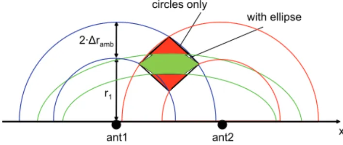
The trilateration procedure for reconstructing point targets from the reflection and transmission scattering data of two antennas is done according to Fig. 1. The two transmit and receive antennas are situated on the x-axis of a local coordi-nate system at the positionsx1=−20λcandx2=20λc, where λcis the free-space wavelength at center frequency. The
an-tennas ant1and ant2are assumed to radiate in the front half space which is valid for many applications so that the shaded area in the figure can be neglected. A point scatterer is sit-uated at positionx=0λc andy=20λcand is illuminated by
Fig. 1. Trilateration algorithm exploiting transmission and reflec-tion informareflec-tion.
several ways. We used Prony’s method (Carriere and Moses, 1992). As depicted in Fig. 1 the point target can be recon-structed in the xy-plane by determining the intersection point between the two circles which determines the possible tar-get position using the reflection data and the ellipse resulting from the TOF of the transmission signal1.
In the following Sect. 2.1 the ambiguity area of a point tar-get is derived in dependence of its position which is a direct measure for the precision of the reconstructed target location. Besides the ambiguity of the target position within a certain area other ambiguities arise in a scenario of multiple point scatterers. These ambiguities are called ghost scatterers. In Sects. 2.2 and 2.3 this kind of ambiguity will be examined. In some cases these ambiguities can be removed or at least be detected which will be explained in Sect. 3.
2.1 Ambiguity area of a single scatterer
The reconstruction accuracy of a point scatterer using the tri-lateration method depends on the SNR (Signal to Noise Ra-tio) of the collected data. The noise power causes an un-certainty in the estimation of the TOF values. Assuming a distance uncertainty of 21rambapplied to both reflection and transmission data the intersection point expands to an area wherein the real scatterer position is located. The ambiguity area for a scatterer directly placed in front of the antennas is shown in Fig. 2. The closest blue circle results from the real scatterer position and the second one is the result obtained with an uncertainty 21ramb. By applying the same uncer-tainty on the right antenna four intersection points will occur between the two blue and the two red circles marking the
1The sum of the distances from ant
1to the scatterer and back to
ant2is constant when the scatterer is placed on an ellipse where the antennas correspond to its focal points.
combination with transmission ellipses with radial uncertainty of 21ramb=0.1λc.
edges of a rhombus which is approximately equivalent to the ambiguity area. The area consists of two red triangles and the hexagon in the middle of the area. Considering the transmis-sion information with the same uncertainty of 21ramb the ambiguity area is shrinked to the green hexagon. As men-tioned before, the area is only an approximation which gets worse in target positions near the x-axis due to the flat angles between the intersection of the red with the blue circles.
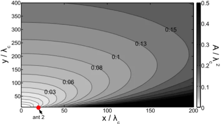
To get an impression on the expected precision for target reconstruction the ambiguity area has been examined in de-pendence on the scatterer position in the xy-plane. Assuming an uncertainty of 21ramb=0.1λc, the values for the
ambi-guity area A related toλ2c are given in Fig. 3. Due to the symmetry of the scenario only the results for positive val-ues of x are displayed. The antennas are placed as before atx1=−20λc andx2=20λc. The lines of same ambiguity
area size are highlighted by the gradation. The lines of same area size exhibit shapes similar to ellipses. With increasing distance of the scatterer in x- and y-direction the ambiguity area enlarges. Especially for scatterers close to the x-axis the ambiguity area can reach big values. Therefore the pro-posed system works best in small distances from the antenna position and in noticeable distance from the x-axis. A fur-ther analysis has shown that a larger antenna distance leads to smaller ambiguity areas. This is obvious since a varia-tion of the antenna distance can be regarded as a scaling of the scenery. At first sight it seems to be the best to separate the antennas in order to benefit from the shrinking ambigu-ity areas. However, with increasing antenna distance also the probability of ghost scatterers increases as shown in the fol-lowing section.
2.2 Ambiguity in multi-target environment
Fig. 3.Ambiguity area size in dependence of scatterer position with a radial uncertainty of 21ramb=0.1λc.
green. The blue circle stands for the TOF between targets1 and antenna 1 with the radiusr11. The first index denotes the target number and the second one is the antenna index. The circlesr11,r32 and the transmissiont2 (transmissions have a target index only due to channel reciprocity) generate two ghost targets on the x-axis. The occurrence of ambiguities depends on the scatterer distances as seen from the antennas. The condition in Eq. (1) for the radial distances of the scat-terers from antenna 2 must be met to generate ambiguities on the x-axis.
r12=r11
r32=r11+dant
r22= t2
2 =r11+ dant
2 (1)
The first scatterer distance can be arbitrarily chosen on the y-axis. Due to the symmetry of the problem the radiusr12is the same asr11. If the radial distances of the following two scatterers increase in steps ofdant/2 two ghost targets will occur symmetrically to the y-axis on the x-axis. Decreas-ing the radial distance belowdant/2 causes the intersection point to move to positive values of y. Increasing the distance will otherwise cause no more intersections and therefore the generation of ghost targets will be avoided. This statement is also valid for other scatterer constellations generating a ghost target on the x-axis. These constellations can be achieved by moving the scatterers along the circles and the ellipse in Fig. 1. All these constellations offer at least one radial dis-tance between the scatterers and the antennas that is closer thandant/2, so the minimal radial distance of the scatterers is dant/2 to avoid ambiguities and can be achieved by aligning the scatterers on the y-axis. All other constellations lead-ing to ghost targets above the x-axis need a radial spaclead-ing of the scatterers of less thandant/2 so ghosts can be com-pletely avoided by scatterer spacing larger thandant/2. If the transmission and reflection signals allow a reconstruction in range cells with the size ofdant/2 or larger there would not be an ambiguity. Utilizing for example a Fourier transform to get the band-limited impulse response will result in the well
Fig. 4. Ghost scatterers resulting from intersections between two circles and one ellipse from three real scatterers.
known resolution cells that have a minimum size depending on the bandwidth B and the propagation velocityc0 accord-ing to Eq. (2).
1rres= c0
2B (2)
To avoid the occurrence of ambiguities the value of 1rres has to be larger thandant/2 according to the preceding ex-planations. This relationship is shown in Eq. (3) and can be regarded as a design criterion for the antenna distance for a given signal bandwidth to suppress ghosts completely. dant≤
c0
B (3)
The expression can vary with different window functions in the frequency domain before applying the Fourier transform or with the beamwidth of the used antennas. The window function causes an increase of the size of a resolution cell. By reducing the beamwidth to less than in the omnidirec-tional case the ambiguities occurring in the area which is not covered by the antenna’s beam can be removed by plausibil-ity. Equation (3) can therefore be regarded as a worst case without windowing and applying an omnidirectional beam.
2.3 Higher order ambiguities
Fig. 5.Occurrence of higher order ghost scatterers in a scenario of five real scatterers.
and the distance between the first and the last scatterer stays dant/2. In the case of five scatterers not only the neighboring scatterers cause ambiguities as shown in Fig. 5. Besides the expected ambiguities formed by the adjacent scatterers that now move to positive y-values due to the smaller scatterer distances there will occur two more ambiguities named “sec-ond order” ambiguities. These new ghosts are formed by the informationr11,t3andr52which now satisfy the condition of a distance smaller thandant/2 and therefore lead to ambigu-ities as in the three scatterer scenario above occurring again on the x-axis. It can be shown easily that seven scatterers lead to “third order” scatterers, nine scatterers lead to “fourth or-der” scatterers and so on if the radial distances between the outer scatterers stay belowdant/2. Assuming no restriction in the system’s resolution an upper limit for the ghost scat-terersNgcan be derived in dependence of the number of the
real scatterersNs and the maximal orderOof the scenario
according to Eq. (4).
Ng=2·
2XO+1
n=3
(Ns+1−n) for n=3,5, ...,2O+1
O= dant
2xs
(4)
The maximal orderOis the largest uneven value indant/2xs
where xs is the radial distance between neighboring
scat-terers. This formula is valid for equally spaced scatterers aligned on the y-axis with a minimal distance ofdant/2 be-tween the nearest and the farthest scatterer and is an upper limit for the occurring ambiguities. The order can be reduced by lowering the antenna distance or increasing the scatterer distance. In Sect. 4Ng is displayed for maximal order in
Fig. 8 up toNs=15. The number of ghost scatterers is
in-creasing exponentially with higher values ofNs. In Sect. 4
the benefit of knowing the upper limit for ambiguities is dis-cussed in order to reduce the number of detected targets.
Fig. 6.Algorithm steps for point target reconstruction in a plane.
3 Algorithm
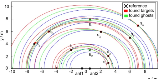
Fig. 7.Example of the reconstruction of 8 scatterers using the trilateration method with plausibility check.
method. Likewise the probability to detect ghost scatterers increases as an exact intersection of both circles and the el-lipse is no more necessary for a scatterer detection. Therefore a plausibility check is performed at the end of the algorithm in step 4.
If the number of the found triangles is larger than the sum of the upper limit for the number of ghost scatterers (see Eq. 4) plus the number of real scatterers (the number of real scatterers is given by the number of targets detected by the Prony algorithm) the algorithm has detected more scatterers than physically possible for the current scenario. The algo-rithm therefore removes the biggest triangles until the upper limit is reached. A further reduction can be achieved by re-moving triangles with ambiguous information. If a triangle is constructed by either a circle or an ellipse only crossing a single scatterer then the point belonging to the spanned tri-angle is unambiguous. An example is depicted in Fig. 4 where the ghost targets on the x-axis consist of the circles and the ellipse of the real targets. The real targets all have at least one circle or ellipse that is uniquely used for their scat-terer reconstruction and can therefore be marked as “real” target. This information allows to identify real scatterers in the whole pool of possible scatterers. This principle does not work with all configurations as the position of a ghost target can for example coincide with a real scatterer which is then marked as ghost target. The next section shows some simula-tion results showing the detecsimula-tion capability of the algorithm.
4 Simulation results
To verify the capability of target reconstruction using the trilateration algorithm a scenario with 8 scatterers is cho-sen which are placed in a rectangular field of the size 20 m×10 m. In Fig. 7 the 8 scatterers are placed at the posi-tions marked as black crosses. The antennas are placed in a distance of 1 m symmetrical to the origin. The
scatter-ing parameters have been determined over a bandwidth of 2 GHz. To obtain realistic values a white noise signal was added to the scattering data. The result for an SNR of 35 dB is shown by the red and green rectangles which mark the re-constructed scatterer positions. The red rectangles have at least one unique information so they can be regarded as real scatterers. The green rectangles mark the scatterers which only use information that is already used for other scatter-ers. The scattererg2 (gstands for “ghost”) for example is generated by the ellipse froms1, the blue circle froms2and the red circle froms3. As explained in Sect. 2.2 the ambi-guities originate from a radial scatterer distance of less than dant/2 which is true for the scattererss1,s2ands3. The same situation leads to the ghostg1which is formed by the scat-tererss5, s6 ands7. Although these scatterers have a large distance among each other, they are separated very closely as seen from the antennas. In contrast the scattererss4and s8are separated with a higher radial distance so they do not generate ambiguities. The figure also gives a hint regarding the accuracy of the reconstruction. As shown in Sect. 2.1 the accuracy degrades with higher radial distance to the anten-nas as can be seen for scatterers8 where the rectangle is a slightly shifted out of the reference position. Another degra-dation can be seen at scatterers5at approximately the same radial distance but a position closer to the x-axis. These con-ditions lead to a stronger deviation of the reconstructed point to the reference position due to the larger ambiguity area.
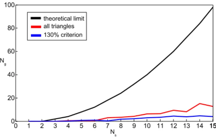
In the example of Fig. 7 the number of ghost scatterers is much less than the theoretical limit of 24 as is shown in Fig. 8. The black curve shows the relation between the num-ber of scatterersNs and the maximum number of ghostsNg
Fig. 8.Number of ghost targets in dependence of real scatterers.
seldom reached in scenarios with randomly spaced scatter-ers. For this reason the theoretical limit is not a reasonable choice for reducing the number of triangles found by the al-gorithm as expected in Sect. 2.3. The red curve shows the result of the algorithm by considering all triangles found in the nearest-neighbor search and is significantly lower than the theoretical limit. In order to reduce the ambiguities due to the number of triangles found by the nearest-neighbor al-gorithm beside the real scatterers and the ghosts, a limit for the number of triangles has been introduced to 130% of the scatterers resolved by the Prony algorithm. Only the smallest triangles are considered which reduces the number of ghost scatterers. The value of 130% has been found to be a good compromise between the number of reconstructed ghost tar-gets and the certainty of reconstructing all physically avail-able scatterers.
The simulations showed that the algorithm detects ghost targets as expected. Due to the generation of further ambigu-ities by the search for triangles it is useful to reduce the num-ber of detected scatterers. The proposed algorithm showed good results with a fixed limit of the resolved triangles.
antenna distance on the one hand leads to a complete elimi-nation of ghosts. On the other hand a possibility of detecting ghost scatterers was presented that provides a save detection of at least some of the real targets in the scenery without limitation in resolution or antenna distance allowing the en-hancement of the reconstruction accuracy by choosing high antenna distances.
References
Carriere, R. and Moses, R.: High resolution radar target modeling using a modified Prony estimator, IEEE T. Antenn. Propag., 40, 13–18, 1992.
Helmbrecht, E. and Biebl, E.: Radar imaging using noncoherent sensors, Proc. IEEE MTT-S International Microwave Sympo-sium Digest, 4 pp., 2005.
Michael, B., Menzel, W., and Gronau, A.: A real-time close-range imaging system with fixed antennas, IEEE T. Microw. Theory, 48, 2736–2741, 2000.
Wenger, J.: Future Trends in Automotive Radar/Imaging Radar, Proc. 28th European Microwave Conference, 1, 636–664, 1998. Yang, Y. and Fathy, A.: Design and Implementation of a Low-Cost