*e-mail: [email protected]
Surface Integrity Analysis when Milling Ultrafine-grained Steels
Alessandro Roger Rodriguesa*, Oscar Balancinb, Juno Gallegoc,
Cleiton Lazaro Fazolo de Assisa, Hidekasu Matsumotoc, Fernando Brandão de Oliveirac,
Suzana Regina da Silva Moreirac, Otavio Villar da Silva Netod
aMechanical Engineering Department, Engineering School of São Carlos, University of São Paulo – USP, Trabalhador São-Carlense Avenue, 400,
CEP 13566-590, São Carlos, SP, Brazil
bMaterials Engineering Department, Federal University of São Carlos – UFSCar, Washington Luís, Km 235, CEP 13565-905, São Carlos, SP, Brazil
cMechanical Engineering Department, Engineering Faculty of Ilha Solteira,
Univ Estadual Paulista – UNESP, Brasil Centro Avenue, 56, CEP 15385-000, Ilha Solteira, SP, Brazil
dPaulista University – UNIP, Presidente Juscelino Kubitschek de Oliveira Avenue,
CEP 15091-450, São José do Rio Preto, SP, Brazil
Received: August 10, 2011; Revised: October 7, 2011
This paper quantifies the effects of milling conditions on surface integrity of ultrafine-grained steels. Cutting speed, feed rate and depth of cut were related to microhardness and microstructure of the workpiece beneath machined surface. Low-carbon alloyed steel with 10.8 µm (as-received) and 1.7 µm (ultrafine) grain sizes were end milled using the down-milling and dry condition in a CNC machining center. The results show ultrafine-grained workpiece preserves its surface integrity against cutting parameters more than the as-received material. Cutting speed increases the microhardness while depth of cut deepens the hardened layer of the as-received material. Also, deformations of microstructure following feed rate direction were observed in workpiece subsurface.
Keywords: milling, surface integrity, microstructure, microhardness, ultrafine-grained steel
1. Introduction
Surface integrity is defined as metallurgical modifications in the surface and surface layer of a workpiece caused by
manufacturing processes1. Nowadays the surface integrity
is strongly discussed given the requirements for mechanical components such as performance, functionality and high reliability. Thus, the surface integrity can play an important role when using the machined parts for instance in mobility
industries2.
Low-carbon steels with ultrafine grains (<5 µm) have been significantly studied due to the gain in mechanical properties aiming at applications in high performance
components3. Several processing routes have been
formulated for this purpose which are supported by phenamena like subgrain/grain formation by severe deformations at room temperature, dynamic transformation of phase induced by deformation, continuous dynamic recrystallization of ferrite at hot work. There are promising perspectives for application of ultrafine-grained steels, not only in sheets, but also in parts with greater dimensions, such as shafts (steering, propulsion, cardan), wheels, impact bars, shock absorbers, universal joints and toothed racks. Thus, the tendency will be to machine these components adopting
techniques so-called high performance cutting, high-speed machining, micromachining or high precision machining.
High-Speed Machining (HSM) is industrially defined when cutting speed is elevated and feed per tooth and depth of cut are diminished normally aiming at finishing
operations4. This technology can be very efficiently applied
in aeronautical, automotive and molds/dies industries to produce dimensionally precise and free-form geometry
parts5,6. But, even if these manufacturing processes
technologically advanced are not properly controlled, such as feed rate oscillations, they may affect the costs, lead-time
and quality of products6. Besides, some advantages of HSM
such as decrease of temperatures and forces can be decisive for workpiece surface integrity. Despite these supposed benefits, many scientific results are still contradictory mainly about workpiece surface integrity.
Saï7 studied the microhardness behavior due to cutting
speed variation and concluded that microhardness in milled
surfaces increased with cutting speed. In contrast, Silva8
verified microhardness was not affected by milling of the AISI H13 steel when cutting conditions were varied. Kannan
and Kishawy9 declare particle volume fraction and average
size profoundly affect the extent of plastic deformation
workpiece volume fraction did not find plastic deformations near machined surface.
The objective of this research was to quantify the influence of the cutting speed, feed per tooth and depth of cut, mainly at high-speed machining, on the microhardness and microstructure of low-carbon alloyed steel with ultrafine grains still not used in machining.
2. Materials and Methods
The milling tests were carried out in a CNC machining center with 11 kW power and 10,000 rpm maximum spindle rotation. A 25 mm diameter cutter tool with two cemented
carbide inserts coated with Al2O3 layer (code R390-11 T3
08M-PM 4030 and grade ISO P25) was employed for the endmill operation adopting down-milling condition.
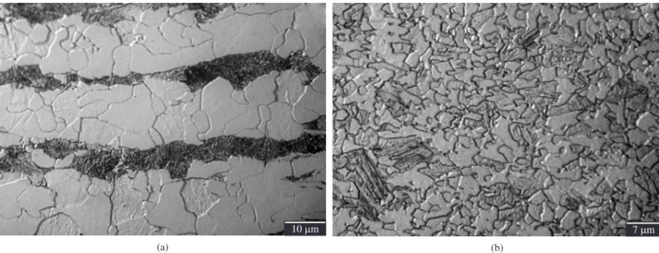
Rolled low-carbon alloyed steel with 10 x 24 x 100 mm was used for milling tests. The main chemical elements are 0.15%C, 1.49%Mn, 0.276%Cr, 0.008%Ni, 0.048%Nb, 0.044%V and 0.016%Ti. The as-received (198 ± 2.6 HV) and ultrafine-grained (322 ± 7.3 HV) materials present ferritic grain size of 10.8 ± 3.8 µm and 1.7 ± 0.32 µm, respectively (ASTM E 112-96 standard). Figure 1 illustrates the microstructure morphology.
Figure 1a shows a microstructure composed by ferrite and pearlite in clear and dark color, respectively, with grain contours well-defined even in ferrite-ferrite interface. The ferrite morphology is polygonal with long and narrow pearlitic structures aligned according to the rolling direction. Figure 1b presents polygonal ferritic ultrafine grains with some probable occurrences of bainite and martensite.
To obtain ultrafine-grained steels, the as-received materials were submitted to microstructural conditioning and thermo-mechanical processing. The first stage consisted in water quenching aiming at obtaining fine martensitic microstructure. The second one based on heating and passes of rolling with reheating in furnace among passes. Finally, the workpieces were heated at intercritical temperature with subsequent water cooling. Figure 2 shows the specimens from as-received and ultrafine-grained steel used for machining tests.
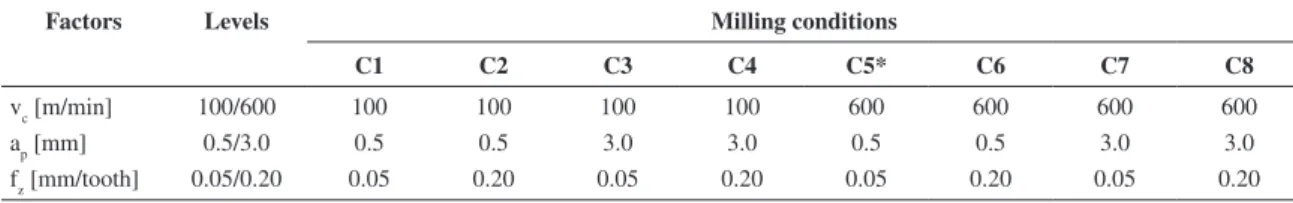
For machining tests, the cutting parameters adopted
were 100 and 600 m/min cutting speed (vc), 0.5 and 3.0 mm
depth of cut (ap) and 0.05 and 0.2 mm/z feed per tooth (fz).
The machining conditions assumed as HSM were extracted
by combining parameters with maximum vc and minimum
ap and fz. All machining tests were carried out twice in dry
condition with 2 mm width of cut (ae) and linear tool path in
the x-axis direction only. The cutting parameters were based
on ranges indicated in Tönshoff et al.4 and Chevrier et al.11. A
new cutting edge was used for each test to assure the equal initial conditions since tool wear should not interfere on the workpiece surface integrity. Table 1 summarizes all milling conditions applied in tests.
Statistical evaluation considering Analysis of Variance
(ANOVA) with 23 factorial design, statistical significance
α = 5%, and two replicates was employed adopting
three factors and two levels such as showed in Table 1. Additionally, the paired test-t (Student’s distribution) was applied for microhardness measurements (workpiece bulk and milled border) by considering n = 4 (samples
Figure 1. a) Rolled as-received material, and b) ultrafine-grained steel.
Figure 2. a) As-received material, b) ultrafine grain (rolled), and c) pre-machined specimen for final milling tests independent on the
size), n-1 = 3 (degrees of freedom) and α = 5% (statistical significance).
For microstructural characterization and microhardness measurements after machining, the milled workpieces were cross-sectionally sawed, hot cupped in bakelite and sanded with 120, 220, 400, 600 and 1000 sandpapers. After, the specimens with 8 × 10 × 10 mm were polished with aluminum oxide (1 and 0.3 µm), diamond past (0.25 µm) and etched using reagent Nital 2% by 5 seconds. The microstructure images were obtained by the Scanning Electron Microscope (SEM).
The microhardness profile beneath milled surface was measured only in ferrite grains using an ultra microhardness tester considering the load-unload method, Vickers indentation (20 and 100 mN for as-received and ultrafine grain material, respectively) and ISO 14577-1 standard. The depth evaluated reached 145 µm and each indentation presented four replications.
To measure the microhardness closest to the milled workpiece border, two pairs of specimens from different machining conditions were cupped in the same sample. Thus, two replicates from a given milling condition were positioned in front of other ones from distinct milling condition. This strategy allowed minimizing the bulging effect and obtaining reliable indentations about 5 µm from the machined workpiece border. In addition, interface junction between workpiece pairs was quite plan due to the milling process, facilitating the contact and minimizing the bulging during metallographic preparation. Figure 3 presents this proposed mounting and examples of uniform indentations are shown in Figure 4.
3. Results and Discussion
Figure 5 presents micrographic images near machined surface. The photos were chosen for groups of machining conditions where feed per tooth was varied intentionally since this parameter did not influence on workpiece microstructure significantly (proved by ANOVA with
p-value = 0.860 > α = 0.05). Thus, Figure 5a reveals a milled
surface of the as-received material unaffected by cutting parameters given the absence of deformation lines of the border grains toward feed rate.
A machined surface with sensitive deformation of grains near milled border may be observed in Figure 5b. This effect probably is associated to the depth of cut rise. Figure 5c shows the region next to the surface machined at HSM where grain deformations were more significant due to the increase of shear rate determined by high cutting speed. Finally, Figure 5d shows that the global influence between the cutting speed and depth of cut caused intense deformation of the
grains near milled border. Figure 5e and 5f (high cutting speed) present the microstructure close to milled surface of the ultrafine-grained workpieces. It was possible to note there is not plastic deformation for any combination of milling parameters. The higher hardness reached by grain refinement imposed strain resistance and preserved the surface integrity of machined surface. The decrease of grain size elevates the grain contours area which act like barriers, hindering dislocations movement and increasing the strain resistance of material.
This microhardness behavior was not verified by
Pu et al.12 when machining biomaterial AZ31Mg alloy.
Similarly to the as-received material, the authors found deformed grains toward the feed rate up to 7 µm beneath machined surface. When the tool cutting edge radius was increased from 30 to 70 µm, the deformed microstructure layer reached 15 µm thickness including microhardness rise by about 60%.
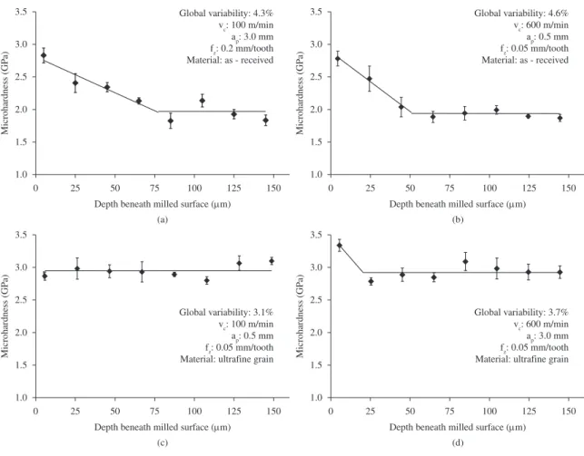
Figure 6 shows the microhardness measurements beneath machined surface. The curves represent all cutting conditions and divide the whole results into well-defined behaviors for each workpiece material.
Table 1. Milling conditions used in the machining tests.
Factors Levels Milling conditions
C1 C2 C3 C4 C5* C6 C7 C8
vc [m/min] 100/600 100 100 100 100 600 600 600 600
ap [mm] 0.5/3.0 0.5 0.5 3.0 3.0 0.5 0.5 3.0 3.0
fz [mm/tooth] 0.05/0.20 0.05 0.20 0.05 0.20 0.05 0.20 0.05 0.20
*High-speed machining condition.
Figure 3. Strategy for cupping of the specimens used for
microhardness measurements and microstructure analyses.
Figure 4. Example of indentations at 5 µm next to the milled
The profiles evidence that microhardness increased next to machined surface for almost all workpieces and this effect was more or less pronounced depending on cutting parameters. It was certified by ANOVA that the feed per tooth did not influence significantly neither microhardness rise nor extension of hardened layer (p-value = 0.860). On the other hand, for as-received material the cutting speed and depth of cut affected decisively the microhardness rise (p-value = 0.032) and hardened layer (p-value ≈ 0),
respectively (Figure 6a and 6b). This behavior demonstrates to be compatible to the microstructure modifications related to grain deformations i.e. cutting speed hardened workpiece through higher shear rate while depth of cut extended the affected layer by means of higher shear level or removed volume.
The microhardness profile for the ultrafine-grained steels did not follow a pattern similar to the as-received material. Three milling conditions varied the microhardness
strongly (C4, C5 and C6), two of them affected slightly (C2 and C7) and other three ones presented null influence (C1, C3 and C8). So, the cutting parameters did not influence statistically the microhardness given the p-value greater than the statistical significance, except for cutting speed (p-value = 0.044). Figure 6c shows a milling condition where all cutting parameters were smallest and Figure 6d represents the machining condition with high cutting speed.
By applying the paired test-t as earlier mentioned, it was possible to prove that the microhardness measurements of the material bulk (as-received and ultrafine grain) are different
statistically since p-value calculated (t3;0.95 = –6.198) is lesser
than the threshold tabulated for the statistical significance (t3;0.95 = 3.182). In addition, the microhardness was equivalent to the macrohardness presented in section 2. Similarly, the comparison among border microhardness data from as-received and ultrafine-grained materials milled under all cutting conditions was different statistically because p-value t3;0.95 = –2.961 < 3.182. Despite the border microhardness measurements for ultrafine-grained steel were greater than those for as-received material, the relative increasing by considering the bulk microhardness was lesser.
All findings abovementioned indicate that ultrafine-grained steel tends to preserve its surface integrity because for most of cutting conditions little or no microhardness variation took place. Even at high cutting speed the material
had a small increase of microhardness and a shallow affected layer, proving that just cutting speed influences on microhardness. Thus, these results are in accordance with the microstructural behavior since the elevation of grain contours area given the grain refinement increased the resistance not only to hardening but also to plastic deformation of material.
Jawahir et al.13 did not also measure microhardness
variations when milling AISI 52100 steel (100Cr6), but some increase should exist near machined surface because compressive residual stress was quantified at depths of up to 250 µm. According to the authors, the main reason for this incompatibility refers to the lower sensitivity of the hardness measurer since induced plastic deformation affects the results of X-ray diffraction more significantly. In addition, the workpiece material does not seem to be prone to strain-hardening in its hardened and annealed state.
4. Conclusions
• The subsurface microhardness of workpiece after
machining may present different behaviors depending on grain size. For larger grain sizes, cutting speed increases the microhardness, depth of cut extends the hardened layer and feed per tooth does not play a significant role. For smaller grain sizes just cutting speed acts on depth of hardened layer;
Figure 6. Microhardness profiles in the subsurface of the workpieces.
1.0 1.5 2.0 2.5 3.0 3.5
0 25 50 75 100 125 150
Depth beneath milled surface (µm)
Microhardness (GP
a)
Global variability: 4.3% vc: 100 m/min ap: 3.0 mm fz: 0.2 mm/tooth Material: as - received
(a) 1.0 1.5 2.0 2.5 3.0 3.5
0 25 50 75 100 125 150
Depth beneath milled surface (µm)
Microhardness (GP
a)
Global variability: 4.6% vc: 600 m/min ap: 0.5 mm fz: 0.05 mm/tooth Material: as - received
(b) 1.0 1.5 2.0 2.5 3.0 3.5
0 25 50 75 100 125 150
Depth beneath milled surface (µm)
Microhardness (GP
a)
Global variability: 3.1% vc: 100 m/min ap: 0.5 mm fz: 0.05 mm/tooth Material: ultrafine grain
(c) 1.0 1.5 2.0 2.5 3.0 3.5
0 25 50 75 100 125 150
Depth beneath milled surface (µm)
Microhardness (GP
a)
Global variability: 3.7% vc: 600 m/min ap: 3.0 mm fz: 0.05 mm/tooth Material: ultrafine grain
• The microstructure near machined surface is more
sensitive for workpieces with larger grain sizes than for smaller ones. Cutting speed and depth of cut are parameters more influent on grain deformation at the border of workpiece;
• Ductile low-carbon steels are also susceptible to
surface integrity alterations, depending on cutting conditions;
• The grain size of workpiece plays a central role
in minimizing interferences on workpiece surface integrity due to the machining process;
• Machiningwithhighercuttingspeedsanddepthsof
cut should be applied with caution, especially in parts with grain size non-refined.
Acknowledgements
The authors are grateful to the São Paulo Research Foundation (FAPESP), Education Ministry Foundation (CAPES) and National Council for Scientific and Technological Development (CNPq) for financial support.
References
1. Field M, Kahles JF and Koster WP. Surface finish and surface integrity. In: American Society for Metals. ASM Metals Handbook: Machining. Ohio: ASM; 1999. v. 16, p. 43-84. 2. Ezugwu EO and Tang SH. Surface abuse when machining
cast iron (G-17) and nickel-base superalloy (Inconel 718) with ceramic tools. Journal of Materials Processing Technology. 1995; 55:63-69. http://dx.doi.org/10.1016/0924-0136(95)01786-0
3. Gao M, Zeng X, Hu Q and Yan J. Laser-TIG welding of ultra-fine grained steel. Journal of Materials Processing Technology. 2009; 209(2):785-791. http://dx.doi.org/10.1016/j. jmatprotec.2008.02.062
4. Tönshoff HK, Friemuth T, Andrae P and Amor RB. High-speed or high-performance cutting - a comparison of new machining technologies. Production Engineering. 2001; 8(1):5-8. 5. Brandão LC, Coelho RT and Rodrigues AR. Experimental and
theoretical study of workpiece temperature when end milling hardened steels using (TiAl)N-coated and PcBN-tipped tools.
Journal of Material Processing Technology. 2008; 99:234-244. 6. Souza AF, Souza AF, Roger AR, Rigatti AMY and Ribeiro
A AL. Mechanistic approach to predict real machining time for milling free-form geometries applying high feed rate.
International Journal of Advanced Manufacturing Technology. 2010; 46(9-12):1103-1111. http://dx.doi.org/10.1007/s00170-009-2183-8
7. Saï WB, Sai WB, Salah NB and Lebrun JL. Influence of machining by finishing milling on surface characteristics.
International Journal of Machine Tools and Manufacture. 2000; 41(3):443-450.
8. Silva MM, Abrão AM, Coelho RT and Campos WRC. Integridade superficial de peças fresadas e retificadas. Revista Máquinas e Metais. 2006; 42(481):136-151.
9. Kannan S and Kishawy HA. Surface characteristics of machined aluminium metal matrix composites. International Journal of Machine Tools and Manufacture. 2006;46:2017-2025. http:// dx.doi.org/10.1016/j.ijmachtools.2006.01.003
10. Rodrigues AR, Matsumoto H, Yamakami WJ, Paulo RGR and Assis CLF. Effects of milling condition on the surface integrity of hot forged steel. Journal of the Brazilian Society of Mechanical Sciences and Engineering. 2010; 32(1):37-43. http://dx.doi.org/10.1590/S1678-58782010000100006 11. Chevrier A, Tidu A, Bolle B, Cezard P and Tinnes JP.
Investigation of surface integrity in high speed end milling of a low alloyed steel. International Journal of Machine Tools and Manufacture.2003; 43(11):1135-1142. http://dx.doi. org/10.1016/S0890-6955(03)00122-6
12. Pu Z, Dillon Junior OW, Jawahir IS and Puleo DA. Microstructural changes of AZ31 magnesium alloys induced by cryogenic machining and its influence on corrosion resistance in simulated body fluid for biomedical applications. In:
Proceedings of the International Manufacturing Science and Engineering Conference; 2010; Erie, USA. Pennsylvania: ASME; 2010. p. 271-277.