ISSN 1546-9239
© 2010Science Publications
Corresponding Author: V.S. Chok, Department of Chemical Engineering, University Technology PETRONAS, 31750 Tronoh, Perak, Malaysia
773
Minimum and Complete Fluidization Velocity for Sand-Palm
Shell Mixtures, Part II: Characteristic Velocity Profiles,
Critical Loading and Binary Correlations
1
V.S. Chok,
2A. Gorin and
2H.B. Chua
1
Department of Chemical Engineering, University Technology PETRONAS,
31750 Tronoh, Perak, Malaysia
2
School of Engineering and Science, Department of Chemical Engineering,
Curtin University of Technology Sarawak Campus,
CDT 250, 98009 Miri, Sarawak, Malaysia
Abstract:Problem statement: In Part I of this research, the main features of the fluidization behavior and characteristic velocities had been reported. Approach: In the present research, the mixtures characteristic velocity profiles for various sand sizes, palm shell sizes and weight percents were presented. It was recognized that there are instances where the characteristic values remain nearly unchanged from its pure sand values. This regime of constant values can be observed in both compartments and can be established depending on the bed properties. The term “Critical loading” is then selected to define the maximum palm shell content (size and weight percent) that can be present in the mixtures where the characteristic velocities remain absolutely of pure sand values. Results: The critical loading increases with the increase of sand size but decreases with the increase of palm shell size. Moreover, it can be observed that the critical loading generally decreases with the increase in particle size ratio, although exception is sighted in the combustor for the mixture with the largest sand size. Overall, the largest sand size has the highest critical loading. Meanwhile, the selected correlations are able to describe the qualitative variation in the characteristic velocities. However, quantitatively, these correlations are unsatisfactory as they are either over-estimate or under-estimate.
Conclusion/Recommendations: It is desirable to establish the regime of critical loading since the mixture characteristic velocities can be pre-determined using bed material properties made up from pure sand (inert) values. Within this regime, a single operational velocity can be set for respective compartment that is independent from variation of palm shell size and weight percent in the mixtures (especially during combustion or gasification). Ultimately, the state of fluidization (e.g., bubbling or vigorously fluidized) and mixing/segregation condition that depend on relative magnitude of operational and characteristic velocities can be identified and maintained.
Key words: Biomass mixing, fluidization velocity, binary correlations
INTRODUCTION
Palm shell cannot be fluidized solely. It is considered as Geldart D particle, a classification for spouting material. However, the addition of a second fluidizable material (sand) in palm shell can facilitate proper fluidization. In Part I of this research (Chok et al., 2009a), the main features of the fluidization behaviour and characteristic velocities using sand-palm shell mixtures were examined with respect to different bed properties. Their distinct patterns and further analysis on the various characteristic velocity relationships
provide insights on the fluidization mechanism and the mixing/segregation tendency. Some interesting works are given in (Chok et al., 2009b; 2007; Fauziah et al., 2008) on hydrodynamic studies of sand-palm shell mixtures. Interested readers are encouraged to refer to them.
The present study reports the characteristic velocity profiles for various sand sizes, palm shell sizes and weight percent in the mixtures and in different compartments. As described later, it is recognized that there are some instances where the mixtures Umf and Ucf values
Fig. 1: Experimental setup (1) compressor; (2) dryer; (3) pressure regulator; (4) rotameter; 5: plenum; (6) perforated distributor; (7) combustor; (8) gasifier; (9) manometer (Chok et al., 2009a)
This regime of constant Umf and Ucf values can be
observed in both compartments and can be established depending on the bed properties.
It is desirable to establish this regime for each compartment since the mixture characteristic velocities can be pre-determined using the bed material properties made up from entirely pure sand (inert) values. Within this regime, a single operational velocity can be set for the respective compartment based on the pure sand value and is independent from the variation of the palm shell size and weight percent in the mixtures (especially during combustion or gasification). Ultimately, the state of fluidization (e.g., bubbling or vigorously fluidized) and the condition of mixing/segregation in each compartment, that depend on the relative magnitude of the operational and characteristic velocities can be identified and maintained. Therefore, it is of great advantage to determine this regime for each compartment and the term “critical loading” is selected. Meanwhile, various published Umf and Ucf
correlations are tested and compared with the experimental values.
MATERIALS AND METHODS
As the apparatus for this study is the same as described in (Chok et al., 2009a), only a brief description is included here. A schematic of the experimental setup is illustrated in Fig. 1. The cold flow model as shown in Fig. 2 has a 0.66 ID and is divided into 2 compartments i.e. combustor and gasifier by a vertical wall in 2:1 cross-sectional area ratio. The effective diameters, De are computed as 25.7 and 41.3
cm for gasifier and combustor respectively (Chok et al., 2009a).
The experiments were carried out in both of the compartments at 0.4 m static bed height. Large amount of bed material is used, i.e., 77 and 101 kg respectively. 4 different types of sand and palm shell sizes are selected as the bed materials. The physical properties of the sand and palm shell are given in Table 1.
Fig. 2: Isometric view of CFBG (Chok et al., 2009a)
Table 1: Palm shell and sand properties
Properties Palm shell Sand Particle size/sieved range (mm) 1.77/(+1.18-2.36) 0.196
3.56/(+2.36-4.75) 0.272 7.13/(+4.75-9.50) 0.341 11.75/(+9.50-14.00) 0.395 Density (kg m−3) 1,500 2.700
Moisture (wt%) 8-10% - Weight percent (wt%) 2, 5, 10 and15% -
RESULTS
Characteristic velocity profiles: Figure 3 shows the Umf and Ucf profiles in the combustor at various palm
shell sizes and weight percent with finest sand of 196 µm. For the smallest size palm shell of +1.18-2.36 mm, both the Umf and Ucf values remain unchanged
from the values of pure sand as in (Chok et al., 2009a). Similarly, for medium size palm shell of +2.36-4.75 mm, these values remain constant except at 15 wt%. With larger palm shell size of +4.75-9.50 mm, the characteristic value changes at 5-10 wt% but further increase of palm shell leads to severe channeling. This channeling condition is also observed for the largest palm shell size of +9.50-14.00 mm where the characteristic velocities increase with the increase of palm shell wt% only up to 5wt%. Settlement of palm shell “chunks” are observed at higher weight percent for palm shell of >4.75 mm even at the maximum capacity of air flow rate (10 times Umf of pure sand).
775
(a) (a)
Fig. 3a and b: Umf and Ucf in the combustor; sand of
196 µm and palm shell of various sizes and weight percent
(a) (b)
Fig. 4a and b: Umf and Ucf in the combustor; sand of
272 µm and palm shell of various sizes and weight percent
Figure 4a and 5a indicate the Umf values for
gasifier and combustor at various palm shell sizes and wt% with river sand of 273 µm.
The Umf values remain unchanged in the combustor
for palm shell size <4.75 mm. Although similarly is found in the gasifier, the Umf increases at palm shell of
+2.36-4.75 mm at 15 wt%. The Umf increases at ≥10
and ≥5 wt% for palm shell of +4.75-9.50 and +9.50-14.00 mm respectively in the combustor. However, in the gasifier, the effect of palm shell of +4.75-9.50 and +9.50-14.00 mm to the Umf is noticeable at 15 wt% and ≥5 wt% respectively.
The Fig. 4b and 5b indicate the Ucf values for
gasifier and combustor using the same river sand and palm shell composition. For palm shell size <4.75 mm, the Ucf values in both compartments remain
nearly unchanged except palm shell of +2.36-4.75 mm at 15 wt% in the gasifier. For palm shell size of +4.75-9.50 mm, Ucf values for gasifier and combustor begin to
show upward trends at ≥10 wt%.
(a) (b)
Fig. 5a and b: Umf and Ucf in the gasifier; sand of272 µm and palm shell of various sizes and weight percent
(a) (b)
Fig. 6a and b: Umf and Ucf in the combustor; sand of
341 µm and palm shell of various sizes and weight percent
(a) (b)
Fig. 7a and b: Umf and Ucf in the gasifier; sand of341 µm and palm shell of various sizes and weight percent
Figure 6a and 7a indicate the Umf values for
combustor and gasifier at various palm shell sizes and wt% with larger sand of 341 µm. No changes in the Umf
is also similarly observed in the gasifier, but with significant Umf increase for palm shell of 2.36-4.75 and
+4.75-9.50 mm at 15 wt%. In addition, for palm shell >9.50 mm, at ≥2 wt%, increase of Umf was observed in
both compartments.
Figure 6b and 7b above indicate the Ucf values for
combustor and gasifier at various palm shell sizes and wt% with quartz sand of 341 µm. No changes in the Ucf
for palm shell size <4.75 mm in the combustor. Similar trend is also obtained in the gasifier except a noticeable Ucf increase for palm shell of +2.36-4.75 mm at 15
wt%. For palm shell of +4.75-9.50 mm in the combustor, there is a marginal Ucf increase at 15 wt%.
A steep increase in Ucf is observed in the gasifier for
palm shell of +4.75-9.50 mm at ≥10 wt%. For palm shell of +9.50-14.00 mm, incremental in Ucf values are
observed at ≥2 wt%.
Figure 8 and 9 indicate the Umf and Ucf values for
combustor and gasifier at various palm shell sizes and wt% with quartz sand of 395 µm.
(a) (b)
Fig. 8a and b: Umf and Ucf in the combustor; sand of
395 µm and palm shell of various sizes and weight percent
(a) (b)
Fig. 9a and b: Umf and Ucf in the gasifier; sand of 395 µm and palm shell of various sizes and weight percent
As shown in Fig. 8a, the Umf values in the
combustor are relatively constant for all palm shell sizes at ≤5 wt%. However, slight decrease in the Umf
values are observed for palm shell sizes of ≤9.50 mm at
≥10 wt%. For the largest palm shell size of +9.50-14.00 mm, the Umf values remain unchanged. Similarly, in
Fig. 8b, the Ucf values in the combustor remain nearly
unchanged for all palm shell sizes at ≤5 wt%. However, slight decrease in the Ucf values at 10 wt% is noticeable
for palm shell of +1.18-2.36 mm and +4.75-9.50 mm. For the largest palm shell size of +9.50-14.00 mm, the Ucf values remain unchanged up to 10 wt% and
decreases at 15 wt%.
In Fig. 9a, the Umf values for palm shell of ≤4.75mm remains fairly constant up to 15 wt% in the gasifier. However, for palm shell size of ≥4.75 mm, at
≥10 wt%, increase of Umf values are observed.
Similarly found in Fig. 9b, the Ucf values for palm shell
of ≤4.75 mm remains constant in the gasifier. For palm shell size ≥4.75 mm, at ≥10 wt%, increase of Ucf was
observed.
Critical loading: Based on all the characteristic velocity profiles shown in Fig. 3-9, it is recognized that there are some instances where the mixtures Umf and
Ucf values remain nearly unchanged from its pure sand
values. Therefore, it is of great advantage to determine this regime for each compartment and the term “critical loading” is selected. “Critical loading” is defined here as the maximum palm shell content (size and weight percent) that can be present in the sand where the mixtures Umf and Ucf values remain absolutely of pure
sand values. These values (of pure sand and mixture) are considered identical when the respective characteristic velocities variations between the bed materials are within ±15%. Table 2 and 3 show the critical loading for Umf and Ucf in the combustor and
gasifier respectively.
Table 2: Critical loading for uMF and uCF in the combustor
Palm shell size (mm)
--- Sand size +1.18-2.36 +2.36-4.75 +4.75-9.50 +9.50-14.00 (µm) Palm shell weight percent (wt%); Umf /(Ucf)
196 15/(15) 10/(5) 2/(2) 2/(0) 272 15/(15) 15/(10) 5/(5) 2/(0) 341 15/(15) 15/(10) 10/(5) 2/(2) 395 15/(15) 15/(15) 15/(15) 15/(10)
Table 3: Critical loading for uMF and uCF in the gasifier
Palm shell size (mm)
--- Sand size +1.18-2.36 +2.36-4.75 +4.75-9.50 +9.50-14.00 (µm) Palm shell weight percent (wt%); Umf /(Ucf)
196 - - - -
777 In both Table 2 and 3, it can be seen that for the smallest palm shell size of +1.18-2.36 mm, up to 15 wt% can be present in the mixture with any sand sizes without resulting significant changes in the mixture characteristic velocities from the pure sand values.
In addition, the critical loading increases with the increase of sand size but decreases with the increase of palm shell size. Meanwhile, the critical loading for the Umf is always equal or larger than the Ucf value in both
of the compartments. Overall, the largest sand size (395µm) has the highest critical loadings in both of the characteristic velocities.
Fig. 10 and 11 show the critical loading as a function of particle size ratio (palm shell/sand) in the combustor and gasifier respectively. The area below the lines and bounded by the horizontal axis represent the regime of the critical loading at various mixture size and composition. Generally, it can be observed that the critical loading decreases with the increase in particle size ratio i.e., in the trend of reducing. However, the formations of intermediate peaks occur in the combustor as shown in Fig. 10 for the mixture with sand of 395µm. This is due to the increased in particles mixing as described earlier (Refer to Ratio of Ucf/Umf)
as observed in the larger compartment. In addition, the critical loading line for the Umf always lie on or above
the values for the Ucf.
Fig. 10: Critical loading in the combustor
Fig. 11: Critical loading in the gasifier
Umf and Ucf values comparison with correlations: The Umf and Ucf values for sand/palm shell mixtures
determined using the common methods for multi-components system allow comparative studies to be carried out from the various published correlations.
Three different binary correlations namely Mourad et al. (1994); Goosens et al. (1971) and Thonglimp et al. (1984) are selected for comparison with experimental Umf values. In addition, 4 different
binary correlations namely Noda et al. (1986); Gauthier et al. (1999) and Rao et al. (2001) are selected for comparison with experimental Ucf values. These
researchers also utilized similar bed material properties and/or Geldart classification. The characteristic values for mixtures within the critical loading are not included since the mixtures Umf and Ucf remain unchanged from
the pure sand values.
In Fig. 12, it can be seen that all the Umf correlations
generally are able to describe the qualitative variation in the sand-palm shell binary mixtures, i.e., the correlations are able to show the increasing or decreasing trends with respect to different sand-palm shell composition. However, as shown in Fig. 13, quantitatively, most correlations are unsatisfactory as they are either over-estimate or under-over-estimate these values.
Fig. 12: Comparison of experimental (EXP) Umf /De
with correlations; ( ) (EXP); ( ) Mourad et al. (1994); ( ) Goosens et al. (1971); ( ) Thonglimp et al. (1984)
Fig. 13: Comparison of experimental (EXP) Umf with
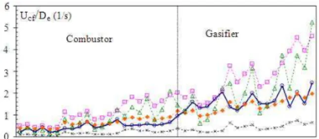
Fig. 14: Comparison of experimental (EXP) Ucf/De
with correlations; ( ) (EXP); ( ) Mourad et al. (1994); ( ) Noda et al. (1986); ( ) Gauthier et al. (1999); ( ) Rao et al. (2001)
Fig. 15: Comparison of experimental (EXP) Ucf with
correlations; ( ) Mourad et al. (1994); ( ) Noda et al. (1986); ( ) Gauthier et al. (1999); ( ) Rao et al. (2001)
Similar found in Fig. 14 and 15, all the Ucf
correlations generally shows the qualitative Ucf
variation for the sand-palm shell binary mixtures but unable to give satisfactory prediction. The results from the various comparisons made on the existing Umf and
Ucf correlations at different palm shell and sand
mixtures clearly show that significant deviation exceeding ±35% from experimental values.
DISCUSSION
On one hand, using smaller sand particle reduces the superficial velocity necessary to establish fluidization when the palm shell components are smaller in sizes or weight percent in the mixtures. However, the tendency for segregation to occur is higher when the resulting particle size ratio (palm shell/sand) is higher due to the lower contribution of particle-particle collision (Chok et al., 2009b).
Consequently, higher superficial velocities are necessary to fluidize the bed mixtures especially if there is any formation of palm shell “chunks” that is enhanced by the present of larger palm shell size and weight percent.
To the contrary, when utilizing large sand particle in the mixture, although greater superficial velocity is required as compared to smaller sand size in order to establish fluidization when palm shell is smaller in sizes or weight percent, the tendency for segregation to occur reduces when the resulting particle size ratio is lower due to the greater contribution of particle-particle collision (Chok et al.,2009b). In addition, the critical loading increases allowing greater proportion of palm shell in all sizes to be present in the mixture without any significant increase of the mixture characteristic velocities from the pure sand value. This condition can be established in both compartments.
CONCLUSION
Taking into account all of the Umf and Ucf values at
different palm shell and sand mixtures and fitting all these curves to a single mathematical equation is seemingly impractical. Although for a specific palm shell size and sand, Umf and Ucf can be fitted into an
equation but no correct equation and model which can correlate all of the data that have been found thus far. Direct utilizing of the experimental values for the operation of sand-palm shell in fluidized bed is essential. Alternatively, identifying the critical loading for this mixture provides a convenient yet robust system where its operational velocity can be pre-determined using bed material properties made up from entirely pure sand (inert) values.
REFERENCES
Chok, V.S., S.K. Wee, A. Gorin and H.B. Chua, 2009a. Effect of particle and bed diameter on characteristic velocities in Compartmented Fluidized Bed Gasifier. Proceeding of the 2nd CUTSE International Conference: Progress in Science and Engineering for Sustainable Development, Nov. 24-25, Curtin University of Technology, Sarawak, Malaysia, pp: 1-5.
779 Chok, V.S., L.F.B. Chin, S.K. Wee, W.W. Tang and
A. Gorin, 2007. Hydrodynamics studies of sand/palm shells binary mixtures in Compartmented Fluidized Bed Gasifier (CFBG). Proceeding of the 1st Engineering Conference on Energy and Environment, Dec. 2007, UNIMAS, Kuching, Sarawak, pp: 301-306.
Fauziah, M., A.R. Nornizar, A. Nornizar, A. Azil Bahari and M.J. Tajuddin, 2008. Cold flow binary fluidization of oil palm residues mixture in a gas-solid fluidized bed system. Pertanika J. Sci. Technol., 16: 201-212.
Gauthier, D., S. Zerguerras and G. Flamant, 1999. Influence of the particle size distribution of powders on the velocities of minimum and complete fluidization. Chem. Eng. J., 74: 181-196, DOI: 10.1016/S1385-8947(99)00075-3
Goosens, W.A.R., G.L. Dumont and G.J. Spaepen, 1971. Fluidization of binary mixtures in the laminar flow reaction. AlChE Symp. Ser., 67: 38-45.
Mourad, M., M. Hemati and C. Laguerie, 1994. Hydrodynamics of fluidized bed dryer: Determination of characteristics of fluidization velocities of mixtures of corn and sand, Powder Technol., 80: 45-54, DOI: 10.1016/0032-5910(94)87004-7
Noda, K., S. Uchida, T. Makino and H. Kamo, 1986. Minimum fluidization velocity of binary mixtures of particles with large size ratio. Powder Technol., 46: 149-154. DOI: 10.1016/0032-5910(86)80021-3 Rao, R., T. Ram and J.V. Bheemarasetti, 2001. Minimum fluidization velocity of mixtures of biomass and sands. Energy, 26: 633-644. DOI: 10.1016/S0360-5442(01)00014-7