Blast Furnace Hearth Lining: Post Mortem Analysis
Bruno Vidal de Almeidaa*, Elton Silva Nevesb, Sidiney Nascimento Silvab, Fernando Vernilli Juniora
Received: November 24, 2016; Revised: February 20, 2017; Accepted: April 07, 2017
The main refractory lining of blast furnace hearth is composed by carbon blocks that operates in continuous contact with hot gases, liquid slag and hot metal, in temperatures above 1550 ºC for 24 hours a day. To fully understand the wear mechanism that acts in this refractory layer system it was performed a Post Mortem study during the last partial repair of this furnace. The samples were collected from diferent parts of the hearth lining and characterized using the following techniques: Bulk Density and Apparent Porosity, X-Ray Fluorescence, X-ray Difraction, Scanning Electron Microscopy with Energy-dispersive X-Ray Spectroscopy. The results showed that the carbon blocks located at the opposite side of the blast furnace tap hole kept its main physicochemical characteristics preserved even after the production of 20x106 ton of hot metal. However, the carbon blocks around the Tap Hole showed iniltration by hot metal and slag and it presents a severe deposition of zinc and sulfur over its carbon lakes. The presence of these elements is undesired because it reduces the physic-chemical stability of this refractory system. This deposition found in the carbon refractory is associated with impurities present in the both coke and the sinter feed used in this blast furnace in the last few years.
Keywords: Carbon refractory, Corrosion, Blast furnace hearth
* e-mail: [email protected]
1. Introduction
Refractories are materials that presents suicient physical and chemical properties stability to be applied for structural purposes in equipment that works in high temperatures in the industries process1. To produce hot metal just a few refractories could be used. Normally, the refractory lining of the conventional blast furnace is made by carbon or graphite blocks. Carbon and graphite is ideal for this particular application because both of them are not wet by hot metal. These refractories has low interfacial tension with the mixture hot metal/ liquid slag. Furthermore, these carbon blocks have excellent thermal shock resistance, good thermal conduction and low thermal expansion coeicients. The wear mechanisms for carbon hearth lining of blast furnaces were reported in the lecture, but it is mainly present as isolated variables. It occurs in function of the high complex real process of hot metal in blast furnaces2,3. In this way, post mortem analyses are an important tool to bring a new over view of the real complex wear process that is responsible for total lifetime of this refractory system.
During the furnace campaign, the refractory lining sufers mechanical and chemical stress such as: oxidation, corrosion by alkalis, disintegration by CO, erosion and dissolution by intense lux of hot metal and slag, liquid penetration (hot metal and slag), iniltration of gaseous phase (alkali vapor and/or carbon monoxide) and thermal stress2,3,4. Both the
liquid penetration and the hot gaseous iniltration are allowed through the open porosity this refractory material5,6,7.
The #2 blast furnace hearth lining of Companhia Siderurgica Nacional (CSN) are composed graphite refractory blocks. This furnace has an historical rate production of 2.40ton/m3.day. In 2009 a second partial repair was conducted in order to repair the refractory hearth lining around the tap hole. During this repair, it was carried out the Post Mortem Study in order to understand the current refractory lining degradation mechanisms to subsidize future developments in this area.
Previous post mortem studies of #2BF, conducted in 2000 during the irst partial repair this current refractory lining showed both iron and slag penetration into this carbon blocks hot face. However, the corrosion mechanism is a result of the chemical nature of the raw materials used to produce hot metal wherein the alkali compound were the main degradation agents7,8.
In 2000 the #2BF showed the typical wear proile coniguration reported by the lecture along the refractory thickness, from the hot face to the cold face: Lost layer; Protective layer; Hot metal penetrated layer; Brittle zone; Slightly changed layer and Unchanged layer8.
The goal of this present work is evaluate the current wear mechanisms that act over this refractory system. It was expected a diferent wear proile in function of changes in the raw materials quality that has a higher degree of impurities, these new raw materials that are rich in some critical elements as sulfur and zinc. Previous studies have showed that the #2BF hearth refractory lining had some hot
metal and slag iniltration in the middle of its campaign, but after 10 years in operation this wear mechanism have changed and news compounds are current responsible for the refractory consumption.
The determination of wear mechanism is fundamental to better understand what happens into the refractory lining during the hot metal production, and it is the basis to decide the better option to protect this refractory layer to improve the furnace campaign. In this way it is possible reduce both the total cost of production and the refractory consumption of this important industrial activity5,6,7.
2. Experimental Procedure
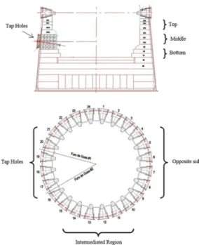
The samples were collected during the last partial repair of #2BF of CSN. The samples were collected in some strategic positions around the hearth lining and the sampling plan was based on this blast furnace hearth historical data. In this way, the samples were collected from three main regions around hearth: a) region around the heart tap hole, b) intermediate region, and c) opposite side of the hearth hole. In each mentioned region it was collected samples of three elevations of hearth lining: from the heart wall bottom, middle and top, Figure 1.
Figure 1. #2 Blast furnace hearth proile showing the region that the samples were collected.
The following procedure was used to collect the samples: a) Drilling the furnace metal shell using a hole saw with 100 mm of diameter, Figure 2; b) Drilling the refractory lining using the same hole saw; c) Taking of the refractory sample; d) Recomposing the sample hole with a new refractory cylinder with a carbonaceous mortar, Figure 3.
Figure 2. Drilling the furnace metal shell to collect the drill core sample.
Figure 3. New refractory cylinder to restore the sample hole into the refractory lining.
The physicochemical characterization was performed at all drill cores’ hot face (in contact with both hot metal and slag) and cold face (in contact with the furnace shell). Using this approach, it is possible to understand e determine both the corrosion path and degree of damage along the sample. The following laboratory techniques were used: chemical analyses by X Ray Fluorescence (XRF) in the equipment model Axios Max of PANalytical, Bulk Density and Apparent Porosity using Archimedes Method, mineralogical phase analysis by X Ray Difraction (XRD). The samples were milled less than #325 ASTM sieve and lately it was subjected to CuKα radiation at 45 kV and 30 mA in a 2Theta range of 10-90º using an Empyrean PANalytical.
The results were analyzed using High Score Plus 3.0 and PDF 2.0 crystallographic data. The non-milled samples were conducted to Scanning Electronic Microscopy (SEM) with X-ray Spectrometry (EDS)6,7,8,9,10,11.
3. Results and Discussion
were studied: Opposite side of the Tap Hole, Intermediated Hearth Region and Region around the Tap Holes. The others two elevations, bottom and top, showed a low pattern wear degree but with the same wear mechanism present in the middle lining region.
3.1. Opposite side of the tap hole
The results of SEM, XRD and the physical properties tests showed that there are no physicochemical diferences between the hot face and cold face samples, and these founded properties are close from the values of brand new refractories, shown in Table 1. The sum of the facts indicated that this particular hearth region has a safe condition to continue in operation in the three elevations analyzed. This lining region doesn’t ofer any danger to the refractory lifetime.
In addition, the X-ray difraction results showed that present phases on both drill cores’ hot and cold faces are the same: graphite and carbon with silicon carbide and corundum, showing that these carbon blocks kept its original physicochemical properties.
3.2. Intermediated hearth region
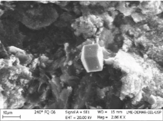
This region is located between the Tap Holes and the Opposite Side of the BF#2 Hearth, previously indicated in Figure 1. In a detailed analyze of the microstructure, Figure 4, it was possible to observe sulfur rhombohedral crystals deposited on the carbon matrix microstructure. This compound was found in the three elevations analyzed.
These results indicate that sulfur vapors generated inside the blast furnace atmosphere percolated through the open porosity of the refractory lining and then condensed on the isotherm near to 450oC. The phase analyzes by X ray difraction conirms the sulfur presence only in the hot face sample. In spite of the sulfur presence in the hot face region, there was no diference between the both hot and cold face apparent porosity.
The sulfur crystals depositions are deleterious to refractory lining because it deteriorates graphite crystals’ hexagonal plates. This afected region becomes weakly and it creates an easier way to both hot metal and slag penetration happens. After it the graphite lakes losses the adhesion between them promoting an easier penetration way for other elements present into the bath. The presence of sulfur was conirmed by XRD. The speciic real mass, speciic apparent mass and apparent porosity are similar despite of sulfur presence on the hot face, Table 2.
Table 1. Physical proprieties of the samples collected from the opposite side of the Tap Holes with standard deviation.
Physical proprieties New Refractory Cold face Hot Face
Speciic Apparent Mass [g.cm-3] 1.71 ± 0.10 1.70 ± 0.15 1.69 ± 0.15
Real speciic mass [g.cm-3] 2.11 ± 0.05 2.09 ± 0.05 2.10 ± 0.05
Open Porosity [%] 16.00 ± 0.50 17.00 ± 0.60 17.00 ± 0.85
Figure 4. Detailed rhombohedral sulfur crystal in the bright phase from hot face sample.
3.3. Region around the tap holes
The remained refractory layer thicknesses present in the region around the hot metal tap holes has just 7% of its initial length, in the three elevations studied. This low remained thickness is improperly to continue in operation, because it is low then the safety thickness for the refractory wall operation. After this study this wall region was totally repaired to achieve the proper conditions of operation. According to this low residual thickness there are no distinctions between the hot and cold sample faces, it was just analyzed as hot face sample.
The penetration of zinc is a result of hot gas iniltration. The zinc has a boiling point at 907 oC. The #2BF operates at 1550oC and its give high chemical activity for these two elements. The zinc vapor sufer oxidation, and then occurs its solidiication and deposition in the isotherm near to 800ºC, Equation 1.
raw materials in current use in this furnace it was founded that new corrosion agent are the elements zinc and sulfur. The presence of these elements reduces the carbon refractory stability and also increases the refractory consumption.
4. Conclusion
This Post Mortem study of the CSN BF#2 Hearth refractory lining has shown that the carbon blocks from Hearth remaining in the regions located at the opposite side and in the intermediate region is well preserved, because these samples keep its original physicochemical proprieties. The region around the Tap Holes has shown severe degradation state. This region is under severe turbulence due to the low of both hot metal and slag. As a consequence, this region has more physical-chemical wear and more degradation by chemical attack mechanisms, mainly per degradation by zinc and phosphorus deposition and also by hot metal and slag iniltration. The presence of zinc, phosphorus and sulfur is associated with the raw materials quality of the BF#2 charge. In addition, the #2BF continues in a normal operation and its refractory lining campaign could be classiied as one of the best in the world due to the long life of this equipment.
5. Acknowledgments
The inancial suport from the CNPq, PDSE CAPES (process number: 11799/13-7), CSN and The University of São Paulo,are greatly acknowledged.
6. References
1. Togobitskaya DN, Khamkhot’Ko AF, Tsivataya NA, Stepanenko DA. Corrosion Activity of Alkali-Containing Slags With Respect to a Blast Furnace Refractory Lining. Refractories and Industrial Ceramics. 2013;54(3):155-160.
2. Silva SN, Vernilli F, Justus SM, Longo E, Baldo JB, Varela JA,
et al. A methodology to investigate the wear of blast furnace hearth carbon refractory lining. Materials and Corrosion.
2013;64(11):1032-1038.
3. Verdeja LF, González R, Alfonso A, Barbés MF. Nodal wear
model: corrosion in carbon blast furnace hearths. Revista de Metalurgia. 2003;39(47):183-192.
4. Almeida BV, Faria RM, Vieira ATO, Silva SN, Vernilli F.
Recycling of steelworks refractories: processing and properties.
Ironmaking & Steelmaking. 2016;43(10):775-779.
Table 2. Physical proprieties of the samples collected from Intermediated Hearth Region with standard deviation.
Physical proprieties New Refractory Cold face Hot Face
Speciic Apparent Mass [g.cm-3] 1.71 ± 0.10 1.70 ± 0.12 1.69 ± 0.15
Real speciic mass [g.cm-3] 2.11 ± 0.05 2.12 ± 0.05 2.10 ± 0.05
Apparent Porosity [%] 16.00 ± 0.50 16.00 ± 0.50 15.00 ± 0.50
Figure 5. Microstructure’s image by SEM/EDS indicating zinc deposition: a) between hexagonal graphite lakes and b) over on the surface the graphite lakes.
( )
Zn
( )g+
CO
2( )g"
ZnO
( , )s1+
CO
( )g1
The formed composts react with silica and alumina that are present in slag, forming liquid phase of potassium and zinc-aluminum-silicate, Equation 2 and 3.
( )
ZnO
( , )s1+
Al O
2 3( )s"
ZnAl O
2 4 1( )2
( )
ZnO
( , )s1+
SiO
2( )s"
ZnSiO
3 1( )3
The analyze results for real speciic mass, speciic apparent mass and apparent porosity, Table 3, show a large dispersion, probably, due to a variation in the concentration of degrading agent presents on the sample9.
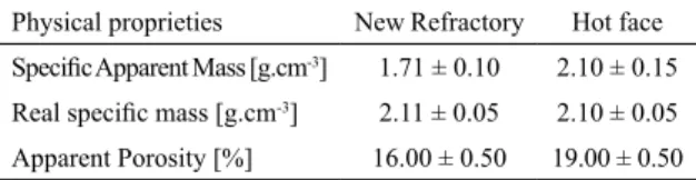
Table 3. Physical proprieties of the samples collected from the Region between the Tap Holes with standard deviation.
Physical proprieties New Refractory Hot face
Speciic Apparent Mass [g.cm-3] 1.71 ± 0.10 2.10 ± 0.15
Real speciic mass [g.cm-3] 2.11 ± 0.05 2.10 ± 0.05
Apparent Porosity [%] 16.00 ± 0.50 19.00 ± 0.50
5. Zheng K, Wen Z, Liu X, Ren Y, Wu W, Qiu H. Research Status and Development Trend of Numerical Simulation on Blast Furnace Lining Erosion. ISIJ International.
2009;49(9):1277-1282.
6. Dmitriev AN, Chesnokov YA, Chen K, Ivanov OY, Zolotykh MO. Monitoring the wear of the refractory lining in the
blast-furnace hearth. Steel in Translation. 2013;43(11):732-739.
7. Duarte RM, Ruiz-Bustinza I, Carrascal D, Verdeja LF, Mochón J, Cores A. Monitoring and control of hearth refractory wear to
improve blast furnace operation. Ironmaking & Steelmaking.
2013;40(5):350-359.
8. Vernilli Jr. F, Justus SM, Mazine A, Baldo JB, Longo E, Varela JA, et al. Hot metal corrosion behavior for graphite refractory
impregnated with TiO2, ZrO2 carrying solutions. Materials and
Corrosion. 2005;56(7):475-480.
9. Almeida BV, Silva SN, Lopes JMG, Passos RL, Longo E, Vernilli F. Implementation of convective heating in Companhia Siderúrgica Nacional Blast Furnace runners. Applied Thermal Engineering.2013;51(1-2):1351-1358.
10. Silva SN, Vernilli F, Justus SM, Marques OR, Mazine A, Baldo JB, et al. Wear mechanism for blast furnace hearth refractory
lining. Ironmaking & Steelmaking. 2005;32(6):459-467.