J. of the Braz. Soc. of Mech. Sci. & Eng. Copyright © 2009 by ABCM January-March 2009, Vol. XXXI, No. 1 / 75
S. M. Avila
[email protected] University of Brasilia – UnB Engineering School of Gama 72405-610 Brasilia, DF, Brazil
P. B. Gonçalves
Emeritus Member, ABCM [email protected] Catholic University - PUC-Rio Civil Engineering Department 22453-900 Rio de Janeiro, RJ, Brazil
Optimal Configurations of Composite
Multiple Mass Dampers in Tall
Buildings
The effectiveness of multiple tuned mass dampers (MTMD) for suppressing harmonically forced oscillations is studied in the paper. In particular the influence of possible connections between the masses of the damper on the main system performance is investigated using four different configurations of a double mass damper. For this, a minimax procedure, which considers all dampers parameters and variables, is used to optimize each configuration and compare their influence on the minimum value of the maximum magnification factor of the main system. A parametric study shows that small variations in the MTMD parameters and the way in which the masses are connected have a marked influence on the main system response. This sensitivity gives the designer more freedom in choosing the proper damper configuration in a practical situation.
Keywords: tuned mass damper, multiple tuned mass damper, vibration control, structural dynamics, damper optimization
Introduction
1A tuned mass damper (TMD) is a passive vibration control
device that has been used in some engineering structures and machines. Usually it consists of a single mass-spring-dashpot system connected to the main structure. In particular, TMDs have been used in recent years in several tall buildings and towers to reduce the energy dissipation demand of these structures under the action of wind loads (Holmes, 1995). In these applications the TMD is placed on the top of the building to maximize its efficiency. The basic concepts for the design of a damped TMD for an undamped structure were presented by Den Hartog (1956). He showed that under a simple harmonic load the main structure could be kept completely stationary when the attached absorber is chosen to be tuned to the excitation frequency. As a result, the vibrational structural energy of the building is transferred to the TMD.
One of the drawbacks when a single TMD is used is its sensitivity to small variations in system parameters, in particular the natural frequency of the structure and/or the TMD damping considered in the design. Uncertainties in the damper and particularly in the system are inherent to engineering constructions. To improve the reliability and effectiveness of the damper, experimental measurements have to be made to determine the dynamic properties of one structure. Alternatively the use of more than one damper has been proposed (Xu & Igusa, 1992; Park & Reed, 2001; Abé & Fujino, 1994; Igusa & Xu, 1994; Jangid, 1999; Jangid & Datta, 1997; Yamaguchi & Harnpornchai, 1993; Kareem & Kline, 1995; Gu et al., 2001; Poovarodom, 2003; Yau & Yang, 2004). In particular, previous studies by Abé & Fujino (1994), Igusa & Xu (1994) and Jangid (1999), among others, have shown that multiple tuned mass damper (MTMDs) can be more effective and robust than a single TMD and that, in this case, the response of the main system is not much influenced by relatively small changes or errors in the values of system parameters used in the TMD design. According to Janjid & Datta (1997) there is a region around the optimum frequency of the damper where the optimized MTMD exhibit an almost constant effectiveness.
Some practical restraints, however, must be observed in the design of a TMD (Abé & Fujino, 1994; Soong & Dargush, 1997). The amount of added mass placed on the top story of a building, the TMD excursion travel relative to the floor, the friction between the
Paper accepted September 2008. Technical Editor: Marcelo A. Savi.
sliding mass and the bearing surface, the amount of spring force on the building and also the enclosure of space occupied by the TMD are some of the issues to be addressed in its design. Now the use of a conception of a system of MTMD can give the designer more freedom in choosing the properties and the best configuration of the multiple dampers.
There are several propositions for the selection of the dampers parameters: one can vary the mass or stiffness of the damper (or both) to cover a certain frequency range encompassing the main tuning frequency. According to Xu & Igusa (1992), it is easier in practice to fix the stiffness of each spring and vary the mass of each damper to cover the desired frequency range.
To improve the MTMD effectiveness, several optimization procedures are found in literature (Jangid, 1999; Tsai & Lin, 1993; Hoang & Warnitchai, 2005; Magluta et al., 2003; Carneiro, 2004; Li & Qu, 2006). According to Jangid (1999), the optimal parameters of a MTMD cannot be obtained by a procedure similar to that employed by Warburton (1982) for a single damped TMD. He determines the optimal parameters by the minimax procedure proposed by Tsai & Lin (1993) for a single damped TMD. An optimization procedure for a MTMD was proposed by Li (2000) for a structure submitted to a base excitation. Hoang & Warnitchai (2005) developed a new method to design MTMD using a numerical optimizer.
In some practical applications the masses of the damper are connected in different ways (Soong & Dargush, 1997), on the other hand the majority of the investigations on MTMDs consider no connection between the dampers. In this paper the influence of possible connections between the masses of the dampers is studied in detail. For this, four different configurations of a double mass damper are compared. In each case the damper parameters are optimized using a minimax procedure that considers mass, tuning frequency and damping ratio of each damper as free variables.
Nomenclature
C = damping matrix
c = TMD damping
C1* = modal damping
di = total displacement
D = location vector
K = stiffness matrix
k = TMD stiffness
K1 *
= modal stiffness
f(t) = modal dynamic excitation force g(t) = external load acting on the structure
M = mass matrix
m = TMD mass
M1* = modal mass
p(t) = interaction force between the TMD and the structure qi = relative displacement
Rd = magnitude of the first element of the complex-frequency
response transfer matrix
y = displacement vector
yi (t) = the absolute lateral displacement of the i=th floor where
the TMD is installed relative to the building base.
Y(ω) = transfer function matrix z(t) = relative displacement
Greek Symbols
α = natural frequency ratio β = forced frequency ratio φ1 = first mode shape
ωs = structure natural frequency ωe = excitation force frequency ωTMD = TMD frequency
ξ = damping ratio µ = mass ratio
System Description and Equations of Motion
System with TMD
The equation of motion of a building-TMD system can be expressed in matrix form as
) ( ) ( ) ( ) ( ) (
. ..
t p t t t
t Cy Ky F D
y
M + + = + (1)
) ( ) ( )
( ) ( ) (
.. .
..
t g t y m t kz t z c t z
m + + =− N + (2)
where M, C and K are, respectively, the mass, damping and stiffness matrixes of the NDOF structural system while m, c and k are the mass damper parameters; F(t) and g(t) are the external loads acting on the structure and TMD, respectively; p(t) = cż (t)+kz(t);yi(t) is
the absolute lateral displacement of the i-th floor of the building relative to its base; z(t) is the relative displacement of the TMD with respect to the floor where it is installed; D is a localization vector whose components dj are given by
⎩ ⎨ ⎧
=≠ =
k j
k j dj
, 1 , 0
(3)
where k is the floor where the damper is installed.
Let us consider a tall building where the natural frequencies are well spaced so that the structure oscillates around a predominant mode. In this case, response vector of the structure can be approximately represented by a single coordinate yN and a mode
shape 1
y = φ1yN. (4)
Substituting Eq. (4) into Eq. (2) and pre-multiplying Eq. (2) by φ1
T
, one obtains the following reduced system
) ( .
* . * .. *
t f kz z c y K y C y
M T+
⎟ ⎞ ⎜ ⎛ + = +
+ φ (5)
where * 1 1
1 φ Mφ
T
M = is the modal mass; * 1 1
1 *
1 M 2ξω
C = ,
2 1 * 1 * 1 M ω
K = and f(t) is the modal dynamic excitation force. Here, ξ1 and ω1 are respectively the damping ratio and natural frequency of the structure.
System with MTMD
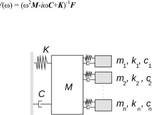
Consider now the simplified SDOF system with n tuned mass dampers with different dynamic characteristics attached to the top floor, as shown in Fig. 1. The main system is characterized by *
1
K ,
* 1
M and * 1
C , while the j-th TMD is characterized by a mass mj,
damping cj and stiffness kj. So, the (n+1) equations of the composite
system are given by
) ( ) ( ) ( ) (
. ..
t t t
t Cy Ky F
y
M + + = (6)
where M, C, and K are the mass, damping, and stiffness structural matrices, respectively; y(t) is an (n+1) vector which represents the main system and masses displacements relative to the main system; F(t) = [f1(t), f2(t), ..., fn(t)]T is the external excitation.
For analysis, the frequency domain approach will be adopted since the dynamic behavior of the structure can often be described more simply by a transfer function in the frequency domain, and the excitations, such as wind loads, are often modeled as stochastic processes characterized by their spectral density functions in the frequency domain. Adopting this approach, fi(t) = fie-iωt and y(t) =
Y(ω)e-iωt. Substituting these expressions in Eq. (6), one obtains Y(ω) = (ω2M-iωC+K)-1F (7)
M
K
C
m , k , c
1 1 1
m , k , c
2 2 2
m , k , c
n n n
. . . .
Figure 1. Structural model: multiple tuned mass damper (MTMD) attached to the main structure.
Rd is defined in this work as the magnitude of the first element
of the complex-frequency response transfer matrix (ω2M-iωC+K)-1 in Eq. (7). The ij element of this matrix represents the permanent response of coordinate i due to a harmonic load applied to coordinate j. The variation of the absolute value of the matrix first element is observed because it represents the permanent response of the main system due to a harmonic load applied to it.
To demonstrate the effectiveness of a MTMD, consider a tall building modeled as a SDOF system with modal parameters, relative to the first lateral bending mode, M*1 = 1.8 x 10
4
t; K*1 = 1.82 x 10
J. of the Braz. Soc. of Mech. Sci. & Eng. Copyright © 2009 by ABCM January-March 2009, Vol. XXXI, No. 1 / 77 ) 4 4 3 5 2 7 3 ( )
(t P sen t sen t sen t sen t
F = ωe + ωe + ωe + ωe (8)
where P is the magnitude of the excitation and ωe is the excitation frequency. Figure 2(a) shows the time response of the building displacement with and without a TMD for P = 40 kN and ωe = 1.0
rad/s. This shows clearly the advantages of using a TMD in a practical case. If the frequency of the periodic force in Eq. (8) is increased to ωe
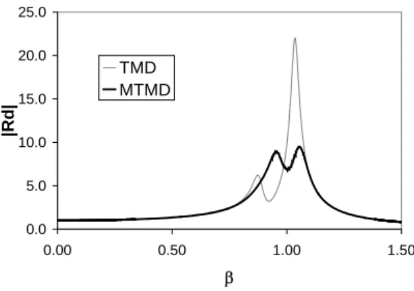
= 1.035 rad/s, slightly higher than the lowest natural frequency of the building, one can observe in Fig. 2(b) that the control system looses its efficiency and the amplitude of steady-state response of the controlled system is much higher than the uncontrolled one. In fact, as shown in Fig. 3, where the magnitude of Rd is given as a function of the
frequency parameter β =ωe/ωs, the response of the building attains
its maximum value at ωe = 1.035 rad/s. This confirms the limitations
of a single damper when the excitation frequency is slightly different of that considered in design.
-0.4 -0.3 -0.2 -0.1 0.0 0.1 0.2 0.3 0.4
0.0 100.0 200.0 300.0
t(s)
D
isplacement (m)
without control TMD
(a) -0,2 -0,2 -0,1 -0,1 0,0 0,1 0,1 0,2 0,2
0,0 100,0 200,0 300,0
t(s) Disp la cem en t (m)
without control TMD
(b)
Figure 2. Controlled and uncontrolled time response of the main system varying excitation frequency: (a) ωe = 1.0 rad/s; (b) ωe = 1.035 rad/s.
To study the efficiency of the MTMD concept, let us consider a MTMD with two equal masses (m1 = m2 = 180 t), each half of that of the original TMD, with the following dynamic characteristics: ω1 = 0.9 rad/s; ω2 = 0.9 rad/s; ξ1 = 0.1; ξ2 = 0.05. The response of the structure in the frequency domain with a single and two independent dampers is shown in Fig. 3. It is clear that the MTMD is less sensitive to variations in the excitation frequency and is more efficient in the vicinity of the natural frequency of the structure.
0.0 5.0 10.0 15.0 20.0 25.0
0.00 0.50 1.00 1.50
β
|Rd|
TMD MTMD
Figure 3. Frequency response of the structure.
The efficiency of the MTMD can be even better by optimizing its parameters and/or by connecting the two masses in different ways as shown in Fig. 4. It is also shown in Fig. 4, for each of the four possible configurations studied in this paper, the total and relative displacement of each mass, respectively di, and qi.
The normalized mass, stiffness and damping matrices in Eq. (6) for each configuration are:
Configuration 1 ⎥ ⎥ ⎥ ⎦ ⎤ ⎢ ⎢ ⎢ ⎣ ⎡ + + = 2 2 1 1 2 1 2 1 0 0 1 µ µ µ
µ µ µ µ
µ M ⎥ ⎥ ⎥ ⎦ ⎤ ⎢ ⎢ ⎢ ⎣ ⎡ = s s s s ω α µ ξ ω α µ ξ ω ξ 2 2 2 1 1 1 2 0 0 0 2 0 0 0 2 C ⎥ ⎥ ⎥ ⎦ ⎤ ⎢ ⎢ ⎢ ⎣ ⎡ = 2 2 2 2 2 1 2 1 2 0 0 0 0 0 0 α ω µ α ω µ ω s s s
K (9)
Configuration 2 ⎥ ⎥ ⎥ ⎦ ⎤ ⎢ ⎢ ⎢ ⎣ ⎡ + + + + + = 2 2 2 2 2 1 2 1 2 2 1 2 1 1 µ µ
µµ µ µ µ
µµ µ µ µ µ
M ⎥ ⎥ ⎥ ⎦ ⎤ ⎢ ⎢ ⎢ ⎣ ⎡ = s s s s ω α µ ξ ω α µ ξ ω ξ 2 2 2 1 1 1 2 0 0 0 2 0 0 0 2 C ⎥ ⎥ ⎥ ⎦ ⎤ ⎢ ⎢ ⎢ ⎣ ⎡ = 2 2 2 2 2 1 2 1 2 0 0 0 0 0 0 α ω µ α ω µ ω s s s
m
1
m
2
M
k2
k
1c1 c2
K, C
q
1 q2
q
p= dp
q
1= d1- dp
q
2= d2- dp
q p Configuration 1
m
1
m
2
M
k 2 k1c1
c 2
K, C
q 1 q 2 q p q2= d2- d1
q
p= dp
q
1= d1- dp
Configuration 2
m
1
m
2
M
k2
k
1c1 c2
K, C
q
1 q2
q
p
q
p= dp
q
2= d2- d1
q
1= d1- dp - d
p
Configuration 3
m
1
m
2
M
k
2
k
1c1 c2
K, C
q
1 q2
q
p
k
3c3
q
p=dp
q
2= d2- d1
q
1= d1- dp - d p Configuration 4 Configuration 3 ⎥ ⎥ ⎥ ⎦ ⎤ ⎢ ⎢ ⎢ ⎣ ⎡ + + = 2 2 2 2 1 1 1 1 0 0 1 µ
µµ µ
µ
µµ µ
M ⎥ ⎥ ⎥ ⎦ ⎤ ⎢ ⎢ ⎢ ⎣ ⎡ − − + = s s s s s s s ω α µ ξ ω α µ
ξ ξµαω
ω α µ ξ ω α µ ξ ω ξ 2 2 2 2 2 2 1 1 1 2 2 2 2 2 2 2 0 2 0 2 0 2 0 2 2 C ⎥ ⎥ ⎥ ⎦ ⎤ ⎢ ⎢ ⎢ ⎣ ⎡ − − + = 2 2 2 2 2 2 2 2 2 1 2 1 2 2 2 2 2 2 2 2 2 0 0 0 0 α ω µ α ω
µ µωα
α ω µ α ω µ ω s s s s s s
K (11)
Configuration 4 ⎥ ⎥ ⎥ ⎦ ⎤ ⎢ ⎢ ⎢ ⎣ ⎡ + + = 2 2 2 2 1 1 1 1 0 0 1 µ
µµ µ
µ
µµ µ
M ⎥ ⎥ ⎥ ⎦ ⎤ ⎢ ⎢ ⎢ ⎣ ⎡ − + − + − − = s s s s s s s s s s s s ω α µ ξ ω α µ ξ ω α µ
ξµαω ξµαω ξµαω ξµαω
ξ ξµαω ξµαω ξµαω
ω ξ 2 2 2 2 2 2 2 2 2 2 2 2 2 2 2 1 1 1 2 2 2 2 2 2 2 2 2 2 2 2 4 2 4 2 2 2 2 4 2 4 2 C ⎥ ⎥ ⎥ ⎦ ⎤ ⎢ ⎢ ⎢ ⎣ ⎡ −− + − − + = 2 2 2 2 2 2 2 2 2 2 2 2 2 2 2 2 2 2 2 2 2 1 2 1 2 2 2 2 2 2 2 2 2 2 2 2 2 2 2 2 2 2 2 2 2 α ω µ α ω µ α ω
µωα µωα µωα µωα
µµωα µωα µωα
ω s s s s s s s s s s s
K (12)
whereωsandξsare, respectively, the natural frequency and damping
ratio of the main system,
s ω ω
α 1
1= (13)
s ω ω
α 2
2= (14)
where ω1 and ω2 are the frequencies of the two masses of the damper, and * 1 1 1 M m =
µ (15)
* 1 2 2 M m =
µ (16)
The minimax procedure as employed by Tsai & Lin (1993)
consists in searching numerically for the design parameters that yield the lowest peak of Rd. The present work is based on this
procedure, but here the maximum value of the response is obtained from the following equation
J. of the Braz. Soc. of Mech. Sci. & Eng. Copyright © 2009 by ABCM January-March 2009, Vol. XXXI, No. 1 / 79 0
2 2
< ∂ ∂
βd R
(18)
which defines the maximum of Rd. Here β is the ratio of frequency
ω to the excitation frequency. Since Eq. (17) is highly non-linear, the Newton-Raphson method is employed to obtain the system parameters.
Numerical Example
Consider the ten-story building analyzed previously by Villaverde & Koyama (1993). The modal characteristics of the reduced SDOF system associated with the fundamental mode are:
M1* = 589.1 t; K1* = 5.94 x 10³ kN/m and C1* = 74.8 kNs/m. Initially the ratio of the damper’s mass to the structural mass is taken as: µ1 = 0.061 and µ2 = 0.042 and the frequency ratios α1 e α2 and damping ratios ξ1 and ξ2 are obtained by the minimax procedure. The optimal parameters for each configuration are presented in Tab. 1. The corresponding optimum Rd values are
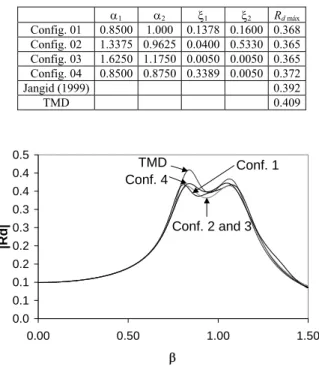
compared with that obtained for a single TMD with an equivalent total mass µ = 0.103, using Den Hartog’s procedure (α = 0.906; ξ = 0.104) and with the optimal value for a MTMD designed according to Jangid’s equations (Jangid, 1999), also in Tab. 1. The optimization procedure as implemented here leads to more efficient dampers, with configurations 2 and 3 leading to the better results. The harmonic response of the main oscillator is plotted as a function of the frequency parameter β in Fig. 5.
Table 1. MTMD optimum parameters and Rd maximum values.
α1 α2 ξ1 ξ2 Rd máx
Config. 01 0.8500 1.000 0.1378 0.1600 0.368
Config. 02 1.3375 0.9625 0.0400 0.5330 0.365
Config. 03 1.6250 1.1750 0.0050 0.0050 0.365
Config. 04 0.8500 0.8750 0.3389 0.0050 0.372
Jangid (1999) 0.392
TMD 0.409
0.0 0.1 0.1 0.2 0.2 0.3 0.3 0.4 0.4 0.5
0.00 0.50 1.00 1.50
β
|Rd|
TMD Conf. 1
Conf. 4
Conf. 2 and 3
Figure 5. Frequency response for harmonic load.
Two important issues in a TMD design are its travel relative to the floor and the enclosure of space occupied by the TMD. To understand the influence of the damper configuration on these issues, the response of each damper is computed considering a harmonic force F(t) = 103 sin (ωt) N with ω = 2.8566 rad/s (β = 0.9). Figure 6 shows the maximum displacements for each mass of
the double damper (d1max and d2max) for each configuration. The best
configuration in terms of travel space is configuration 3, but configuration 2 could lead to less enclosure space.
0 0,5 1 1,5 2 2,5 3
Configuration
Ma
xi
m
u
m
Di
space
me
nt
(mm)
d2 máx 1,44929 2,42523 2,04078 2,85621
d1 máx 2,099 1,2914 1,133 1,59021
1 2 3 4
Figure 6. Maximum displacement for each mass of the damper obtained from the time response.
In the previous example the mass ratios µi were kept constant in the optimization procedure. Now the procedure is repeated considering also the parameters µ1 and µ2 as design variables. The optimum parameters are shown is Tab. 2 together with the corresponding minimum value for the maximum magnification factor Rd. In each case the total mass ratio is kept constant and equal
to µ = 0.1. Again configurations 2 and 3 are more efficient. In this optimization process the response of configuration 1 is independent from the ratios µi. The inclusion of the mass ratios in the
optimization process leads to even better results for Rd máx .
Table 2. Optimum parameters for µ = 0.1.
α1 α2 ξ1 ξ2 µ1 µ2 Rd máx
Config. 01 0.9 0.9 0.2 0.2 - - 0.3977
Config. 02 1.1 0.9 0.05 0.35 0.08 0.02 0.3560 Config. 03 1.1 0.9 0.05 0.35 0.08 0.02 0.3560 Config. 04 1.1 0.8 0.05 0.25 0.03 0.07 0.3942
0 1 2 3 4 5
Configuration
Maximum Dispacement
(m
m
)
d2 máx 1.66231 3.9229 3.33643 1.95298
d1 máx 1.66231 1.54881 1.54883 1.5739
1 2 3 4
Figure 7. Maximum displacement.
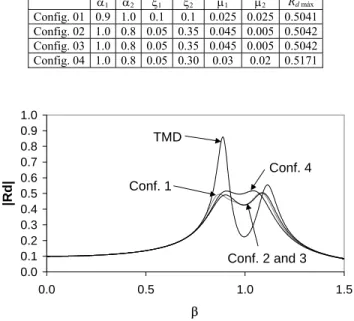
Now consider a MTMD with total mass ratio µ = 0.05. The optimized parameters are presented in Tab. 3. Figure 8 shows the frequency response for this case. Here for the mass ratio is more evident than the results for a MTMD, which are less sensitive and more effective than the results obtained for a single TMD.
Table 3. Optimum parameters for µ = 0.05.
α1 α2 ξ1 ξ2 µ1 µ2 Rd máx
Config. 01 0.9 1.0 0.1 0.1 0.025 0.025 0.5041
Config. 02 1.0 0.8 0.05 0.35 0.045 0.005 0.5042
Config. 03 1.0 0.8 0.05 0.35 0.045 0.005 0.5042
Config. 04 1.0 0.8 0.05 0.30 0.03 0.02 0.5171
0.0 0.1 0.2 0.3 0.4 0.5 0.6 0.7 0.8 0.9 1.0
0.0 0.5 1.0 1.5
β
|Rd|
TMD
Conf. 4 Conf. 1
Conf. 2 and 3
Figure 8. Frequency response for harmonic excitation with passive element (µ = 0.05)
The influence of the ratio between the mass of the two dampers
2 1/µ
µ on the value of Rd máx is shown in Fig. 9 for a total mass µ =
0.05. To obtain the optimal value for Rd, for configuration 1, the
best option is to adopt µ1=µ2; for configurations 2 and 3 m1 must be larger than m2, while for configuration 4 one mass must be approximately 50% higher than the other.
0.5 0.51 0.52 0.53 0.54 0.55 0.56 0.57 0.58
0.0 1.0 2.0 3.0 4.0 5.0 6.0 7.0 8.0 9.0
µ1/µ2
Rd
m
á
x
Configuration 1
0 0.5 1 1.5 2 2.5
0.0 1.0 2.0 3.0 4.0 5.0 6.0 7.0 8.0 9.0
µ1/µ2
Rd
má
x
Configuration 2
0 0.5 1 1.5 2 2.5
0.0 1.0 2.0 3.0 4.0 5.0 6.0 7.0 8.0 9.0
µ1/µ2
Rd
máx
Configuration 3
0.51 0.52 0.53 0.54 0.55 0.56 0.57 0.58 0.59
0.0 1.0 2.0 3.0 4.0 5.0 6.0 7.0 8.0 9.0
µ1/µ2
Rd máx
Configuration 4
J. of the Braz. Soc. of Mech. Sci. & Eng. Copyright © 2009 by ABCM January-March 2009, Vol. XXXI, No. 1 / 81 The use of multiple tuned mass dampers to control the global
response of a structure has been investigated in this paper. In the present study four different configurations of a double damper system are studied and their optimal properties are numerically obtained for minimum displacement of the main structure. The
minimax procedure as implemented here considers as design
variables the mass ratios, the damping ratios and tuning frequencies of the dampers. The performance of each control system is assessed by detailed parametric studies. These results show that, independent from the damper configuration, MTMDs can enhance the effectiveness of the control system when compared with the performance of a single optimized TMD. Results also show that the system response is sensitive to small variations in the mass, stiffness and damping parameters. The consideration of all these parameters as design variables leads to the smallest peaks possible of the response in the frequency domain.
The connection between the masses of the dampers has a measurable influence on the performance of the composite damper giving the designer a certain flexibility in important design issues, such as the amount of added mass placed on the top story of a building, TMD travel relative to the floor, the amount of spring force on the building and enclosure of space occupied by the TMD.
Acknowledgment
The research work in this paper was partially supported by CAPES, the human resources formation agency of the Brazilian Ministry of Education. This support is gratefully acknowledged.
References
Abé, M. and Fujino, Y., 1994, “Dynamic characterization of multiple
tuned mass dampers and some design formulas”, Earthquake Engineering
and Structural Dynamics, Vol.23, pp. 813-835.
Carneiro, R.B., 2004, Vibration control of high buildings using multiple tuned mass dampers (MTMD) (in Portuguese), MSc Thesis, University of Brasilia, Brasilia.
Den Hartog, J.P., 1956, “Mechanical Vibrations”, McGraw-Hill, New York. Gu, M., Chen, M.R. and Chang, C.C., 2001, “Parametric study on multiple
tuned mass dampers for buffeting control of Yangpu bridge”, Journal of Wind
Engineering and Industrial Aerodynamics, Vol. 89, pp. 987-1000.
Hoang N. and Warnitchai P., 2005, “Design of multiple tuned mass
dampers by using a numerical optimizer”, Earthquake Engineering and
Structural Dynamics, Vol. 34, No. 2, pp. 125-144.
Holmes, J.D., 1995, “Listing of installations”, Engineering Structures,
Vol. 17, No. 9, pp. 676-678.
Igusa, T. and Xu, K., 1994, “Vibration control using multiple tuned mass
dampers”, Journal of Sound and Vibration, Vol. 175, No. 4, pp. 491-503.
Jangid, R. S. and Datta, T.K., 1997, “Performance of multiple tuned
mass dampers for torsionally coupled systems”, Earthquake Engineering and
Structural Dynamics, Vol. 26, pp. 307-317.
Jangid, R. S., 1999, “Optimum multiple tuned mass dampers for
based-excited undamped system”, Earthquake Engineering and Structural
Dynamics, Vol. 28, pp. 1041-1049.
Kareem, A. and Kline, S., 1995, “Performance of multiple mass
dampers under random loading”, Journal of Structural Engineering, Vol.
121, No. 2, pp. 348-361.
Li, C., 2000, “Performance of multiple tuned mass dampers for attenuating undesirable oscillations of structures under the ground
acceleration”, Earthquake Engineering and Structural Dynamics, Vol. 29,
pp. 1405-1421.
Li, C. and Qu, W., 2006, “Optimum properties of multiple tuned mass dampers for reduction of translational and torsional response of structures subject to ground acceleration”, Engineering Structures, Vol. 28, pp. 472-494.
Magluta, C. Ainsworth Jr., G.O. and Roitman, N., 2003, “Comparison between multiple vibration absorbers and single absorbers systems”. In: Proc. of COBEM XVII Int. Cong. Mech Eng., São Paulo.
Park, J. and Reed, D., 2001, “Analysis of uniformly and linearly distributed mass dampers under harmonic and earthquake excitation”,
Engineering Structures, Vol. 23, pp. 802-814.
Petersen, N.R., 1980, “Design of large scale TMD”. In: Proceedings of Structural Control, North Holland, Leipholz, H.H.E. ed., pp. 581-596.
Poovarodom, N., Kanchanosot, S. and Warnitchai, P., 2003, “Application of non-linear multiple tuned mass dampers to suppress
man-induced vibrations of a pedestrian bridge”, Earthquake Engineering and
Structural Dynamics, Vol. 32, pp. 1117-1131.
Soong T.T. and Dargush S.F., 1997,“Passive Energy Dissipation Systems in Structural Engineering”, John Wiley & Sons, Chichester.
Tsai, H. and Lin, G., 1993, “Optimum tuned-mass dampers for minimizing steady-state response of support-excited and damped systems”,
Earthquake Engineering and Structural Dynamics, Vol. 22, pp. 957-973. Villaverde, R. and Koyama, L.A, 1993, “Damped resonant appendages
to increase inherent damping in buildings”, Earthquake Engineering and
Structural Dynamics, Vol. 22, pp. 491-507.
Warburton, G.B., 1982, “Optimum absorber parameters for various
combinations of response and excitation parameters”, Earthquake
Engineering and Structural Dynamics, Vol. 10, pp. 381-401.
Xu, K. and Igusa, T., 1992, “Dynamic characteristics of multiple
substructures with closely spaced frequencies”, Earthquake Engineering and
Structural Dynamics, Vol. 21, pp. 1059-1070.
Yamaguchi, H. and Harnpornchai, N., 1993, “Fundamental characteristics of multiple tuned mass dampers for supressing harmonically
forced oscillations”, Earthquake Engineering and Structural Dynamics, Vol.
22, pp. 51-62.
Yau, J. and Yang Y., 2004, “A Wideband MTMD System for Reducing the Dynamic Response of Continuous Truss Bridges to Moving Train