Phonon Multiplexing Through 1D Chains
A. Avila and D. Reyes∗
Andes University, Carrera 1A 18 A 12, Bogot ´a, Colombia
(Received on 30 October, 2008)
Recently, phonon propagation through atomic structures has become a relevant study issue. The most impor-tant applications arise in the thermal field, since phonons can carry thermal and acoustic energy. It is expected that technological advances will make possible the engineering of thermal paths according to convenience. A simple phonon multiplexer was analyzed as a spring-mass model. It consists of mono-atomic chains of atoms with a coupling structure between them. Forces between atoms follow Hooke’s law and are restricted to be first nearest neighbor interaction. It was possible to establish simple rules on constitutive parameters such as atom masses and bonding forces that enable one to select a wavelength of transmission. The method used enables the study of structures of much greater complexity than the one presented here.
Keywords: Phonon multiplexer; Frequency selector
1. INTRODUCTION
The ability to control the propagation of heat has attracted much attention in part due to the challenge of heat removal from electronic devices [2]. Interest in phonon transport heightened since it is the dominant heat carrier in insulators. The capacity to select the phonon propagation path over sev-eral options makes possible the consideration of phonon se-lectivity as a tool for the engineering of thermal and acous-tic properties of materials and structures using a bottom-up approach. Controlling phonon transmission is also interest-ing because of the possibility of engineerinterest-ing forbidden and allowed energy band gaps [1,3,4].
Preliminary studies on phonon propagation through two mono-atomic chains of atoms showed that is possible to se-lect a particular transmission path out of several possibilities [1]. In this study, transmission coefficients were calculated by Green’s function formalism. We have implemented a sim-ple numerical method in MATLAB to analyze the scattering and filtering of phonons in 1D atomic structures modeled as spring-mass chains. Our model allows one to tune the wave-lengths by careful selection of the atomic masses and inter-acting forces/coupling between atoms. More complex struc-tures could be analyzed using the same numerical method; 1D analysis can be set up just specifying a matrix of masses and a matrix of their bindings force constants.
The plan of this paper is as follows. We begin by describing the implemented numerical method for calculating scattering on 1D structures. Then we verify previous results [1] using this numerical method. Finally we propose novel structures to control phonon propagation as well as simple rules of design.
2. NUMERICAL METHOD
We consider here a lattice as a mass-spring network. All masses lay on the same plane; their displacements are ruled by the Hook’s law along a single degree of freedom
perpendic-∗Electronic address:a-avila,[email protected].
ular to the containing plane. In other words, only transverse propagation modes are taken into account.
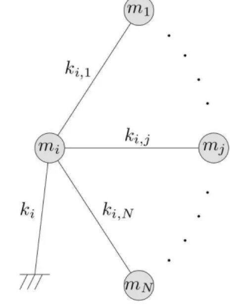
FIG. 1: Schematic of a simple mass in the network.
The numerical method used to solve the transmission and reflection coefficients of phonons through the structure is based on the discrete finite differences method. Each mass mi is connected to anothermj by a spring with a force con-stantki j. It is also coupled to a fixed substrate through another springki. Using Hooke’s and Newton’s Laws, the motion of i-th mass (Fig. 1) is given by
mi d2ui
dt2 = N
∑
j=1,j6=iki,juj−ui N
∑
j=1,j6=iki,j−βiui, (1)
whereuiis the displacement ofmiaround its equilibrium po-sition. Taking Fourier transform, Eq. (1) transforms into
0= N
∑
j=1,j6=iki,juj+
Ã
ω2mi− N
∑
j=1,j6=iki,j−βi
!
Equation (2) specifies the oscillation amplitude of every atom in the system as a function of the masses, force con-stants and oscillation frequency (ω). Although, it is desired to model the system behavior as a function of the wave number, and it should be noticed that there is no term involving the temperature. At low temperature, the network is only excited by the entering phonon.
FIG. 2: Network with one input and many outputs. Ris reflection coefficient andTiis the transmission coefficient at outputi.
The network has a unique input but several outputs. Each of these is connected to a mono-atomic chain of atoms (Fig. 2). The mono-atomic chains have semi-infinite length and each one has the same characteristic mass (m1)and force constant (k’); the separation between consecutive masses is a. This condition implies that the propagating waves (time indepen-dent) moving in and out the system are given by
un(xn) =Ane±ikxn,xn=na,n=...,−1,0,1,2, .... (3) This assumption also sets a condition on the dispersion re-lation of the reflected and transmitted waves [1]
ω2=2k′ m1
(1−cos(ka)) +β1 m1
, (4)
wherekis the wave vector.
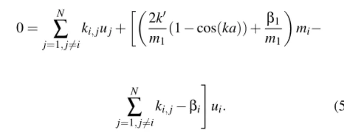
From Eq. (4) and Eq. (2), it is possible to obtain a single equation which models the behavior of the network
0= N
∑
j=1,j6=iki,juj+
·µ
2k′ m1
(1−cos(ka)) +β1 m1
mi−
N
∑
j=1,j6=iki,j−βi
#
ui. (5)
As long as the waves entering and exiting are given by Eq. (3) it is possible to establish that these waves are
uIn(xn) =Aeikxn+Be−ikxn uOutj (xn) =Cjeikxn
;xn=na, (6)
whereA andB represent the amplitude of the incident and reflected waves respectively; andCj is the amplitude of the wave exiting from the jth output. Now, using Eq. (6) we set the following boundary conditions
uIn(0) =A+B(a)
uIn(−1) =Ae−ika+Beika(b) uOutj (0) =Cj(c)
uOutj (1) =Cjeika(d)
, (7)
Boundary conditions in Eq. (7) only take into account the value of the amplitude at the input and outputs and the previ-ous and next position respectively.
Combining Eq. (2) and Eq. (7) the following system is obtained
A
"
k′+∑N
i6=p
kpi+kp−ω2mp−k′e−ika
#
=B
"
ω2m
p− N
∑
i6=p
kpi−kp−k′−k′eika
#
+ ∑N
i6=p kpiui
Ak′=Bk′+ ∑N
i6=q,p kqiui−
"
ω2m
q− N
∑
i6=q kqi−kq
#
uq
0= ∑N
i6=j kjiui+
"
mjω2− N
∑
i6=j kji−kj
#
uj
0= ∑N
i6=sj
ksjiui+Cj "
ω2m
sj−
N
∑
i6=sj
ksji−ksj−k
′+k′eika
#
0= ∑N
i6=sj,rj
krjiui+ "
ω2m
rj−
N
∑
i6=rj
krji−krj #
urj+k
′C j
wherek′is the force constant of the input and output chains, pis atom bonded to the input chain,sj is the atom bonded to jth output chain,qis the atom bonded to thepatom (pcan be only bonded to the input chain andqatom),rjis the previous atom bonded to thesjatom.
The system given by Eqs. (8) was solved using MATLAB. In order to make the model adaptable to any spring-mass net-work, the input parameters were selected as follows:
• A matrix containing all the constant forces between each pair of atoms. The position of the force constant value in the matrix specifies the atoms which are linked by the corresponding spring.
• A vector containing the mass values of each atom.
• A vector containing the force constants attaching each mass to a ‘frozen’ substrate.
3. RESULTS
3.1. Dobrzynski Network
Dobrzynski [1] proposed a simple phonon network in which traveling phonons can flow from one atomic chain to another at certain wave vector. The structure is composed by two identical linear mono-atomic chains with characteristic massm. These chains are bonded to a fixed substrate by linear force constantK. The distance between neighboring atoms is d. The atomic interaction is reduced to the first neighbors by a linear force constantβfor oscillations perpendicular to the substrate plane, so only phonon transverse modes are being taken into account.
Both chains are connected to two additional atoms of mass M which are connected together and deposited on the same substrate as shown in Fig. 3. The force constant binding the chains and the new atoms isβ1. The force constant between atoms 5 and 6 in Fig. 3 isβ2, both atoms are also fixed to the substrate, the force constant involved in this case isK′.
FIG. 3: Phonon selector proposed by Dobrzynski [1]. It has one input and three outputs.
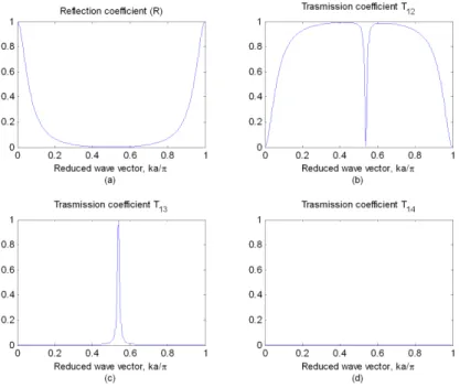
Dobrzynski [1] analytically showed that a unitary transmis-sion coefficientT13(from input to output 3 in Fig. 3) could be achieved by setting the parameters of the system as follows: M/m= 1,K/β= 1,K′/β= 2.8,β1/β= 0.2 andβ2/β= 0.04. These results were verified applying the numerical method above explained as shown in Fig. 4. This figure shows the re-flection and transmission coefficients for the mass-spring net-work shown in Fig. 3 as function of the reduced wave vector kdobtained from the simulations performed. It should be no-ticed thatT13 has a peak, reaching unity at a reduced wave vector slightly aboveπ/2.
This unitary peak occurs at a unique reduced wave vector. Several simulations varying the relationsM/m,β1/βandK/
βwere done showing that the reduced wave vector in which the peak transmission (T13)occurs can be selected as desired from a range between 0.1πand 0.8π.
Figure 5 presents how the reduced wave vector in which transmission peak (T13) occurs and the magnitude of such peak is affected by the mass ratioM/m. This effect may be ex-plained by the direct relation between the coupling resonance and mass ratio. Since the central wave vector is always de-creasing, there is a unique mass ratio that makes possible the tuning of the system at a desired wave length in whichT13is maximal.
It should be noticed that peak’s magnitude in Fig. 5 will be unitary whenM/m= 1. For other values, the magnitude is less than 1. However, within the range 0.66 to 2.6 the peak’s magnitude is above 0.9. This makes it possible to tune the system at any wave vector between 0.15πand 0.8π.
On the other hand, we define the quality factor (Q)as the ratio between the central wave vector (k0)and the width (∆k) of the region which corresponds to a transmission coefficient (T13)greater than half peak value. According to this, it was found that the quality factor is over 30 when the ratioM/mis between 0.6 and 3 as shown in the Fig. 6.
The relation betweenβ,β2andβ1is another tuning param-eter. By satisfyingββ2 =β21, the transmission peak reaches its maximum value, as shown in Fig. 5. This relation makes possible to choose two of three parameters (β,β2,β1)in order to tune the network. Fig. 7 presents the peak transmission as a function ofβ1(β= 1,β2= 0.04). It should be noticed that the optimum value ofβ1is 0.2, which corresponds to the square root ofβ2.
Figure 8 shows the central wave vector forT13as a function of the ratioK/β. This implies that the force constant binding the atomic chains to a fixed substrate could be used as an input parameter to tune the system. According to Fig. 8,K/βmay be used to choose wave vectors between 0.15πand 0.71πwith a peak magnitude greater than 0.9.
3.2. Simple Chain
FIG. 4: Performance of the system in Fig. 3 obtained by simulations. (a) Reflection coefficient. (b) Transmission coefficient from input to output 2. (c) Transmission coefficient from input to output 3. (d) Transmission coefficient from input to output 4.
FIG. 5: Peak value and wave vector where transmission peak occurs as function of masses ratio.
FIG. 6: Quality factor for Dobrzynski network as function of the ratioM/m.
FIG. 7: Peak value and wave vector where transmission peak occurs as function of spring constants ratio.
FIG. 9: Mono-atomic chain with an impurity.
as is shown in Fig. 9. In this case we want to establish the system parameters to select a single wavelength at which the vibrations may pass across the inserted mass; in other words we want to construct a simple phonon filter. When an incom-ing wave reaches the inserted mass, it will be dispersed, creat-ing a reflected and a transmitted wave. The goal is to obtain a unitary transmission coefficient at any arbitrary wave vector.
Letb=µ/κwithµ=m1/m2andκ=k1/k2. Wherek1and m1are the force constant and mass of the mono-atomic chain respectively;k2is the force constant linking the impurity with its closest neighbors andm2is the mass of the inserted mass.
In order to obtain a single wave vector in which transmis-sion is close to 1,m2andk2have to be smaller thanm1and k1respectively. In others words,µ andκhave to be greater than 1. Ifm2andk2are too small, the bonding between the two halves of the chain will be very loose and the transmission would be possible only for a single resonant frequency.
FIG. 10: Quality factor as a function ofκ.
According to simulations, it is possible to control the qual-ity factor. This means that we can specify the device selectiv-ity. Keepingb= 1 (i.e. κ=µ), a quality factor between 0 and 350 can be achieved by taking values ofκbetween 3 and 200. The final relation is almost linear, as is shown in Fig. 10. A simple linear regression gives the following expression:
κ=0.575Q+1.53. (9)
Equation (9) enables the choice of filter quality factor by setting the value ofκ.
Figure 11 shows the central wave number of the filter as a function ofb. Three intervals can be identified. Interpolating the curve in Fig. 11, the parameterbcan be expressed in terms ofkas follows:
FIG. 11: Filter central wave vector as function ofb.
b(k) =
4.527¡ka π
¢2
3.03¡ka
π
¢
−0.5157 2−4.527£¡ka
π
¢
−1¤2 ,
0<ka π <0.33
0.33<ka π <0.66
0.66<kaπ <1
. (10)
Equation (10) gives a simple rule for tuning the filter at any reduced wave vector.
As an example, suppose that it is desired to tune the filter at a central wave vectork= 0.6πwith a quality factor over 80. First, using Eq. (9) we find thatκ= 50 is enough to achieve the minimum quality factor; then, using Eq. (10) we find that b= 1.30, which means thatµ= 65. The final filter behavior is shown in Fig. 12, and it clearly demonstrates the validity of the tuning relations derived.
Fig. 12. Filter tuned at k = 0.6ʌ.
0 0.1 0.2 0.3 0.4 0.5 0.6 0.7 0.8 0.9 1
0 0.1 0.2 0.3 0.4 0.5 0.6 0.7 0.8 0.9 1
Reduced wave number, kd/S
T
ra
n
s
m
is
s
io
n
c
o
e
ff
ic
ie
n
t
FIG. 12: Filter tuned at k = 0.6π.
3.3. Bilinear Chain
creating two filters. This new system is expected to behave like a wavelength based selector.
FIG. 13: Bilinear chain, composed by one input and two outputs.
For the system in the Fig. 13, after several simulations it was determined that the maximum values on the transmission coefficients are achieved when following conditions are satis-fied:k2=k1,k3= 0.7k1andm4= 1.31m1. Additionally we have to declare the following set of parameters:
κ1=k1k4κ2=k1k5 µ1=mm1
2µ2= m1 m3 b1=µ1κ1b2=µ2κ2
. (11)
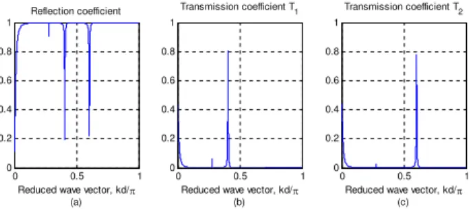
As an example, it is desired to tune the first filter at 0.4πand the second one at 0.6π, each one with a quality factor greater than 80. Using Eq. (9) and Eq. (10) we propose the following parameter values: κ1=κ2= 50,µ1= 34.8 andµ2= 65. The result filter behavior is presented in Fig. 14.
0 0.5 1
0 0.2 0.4 0.6 0.8 1
Reduced wave vector, kd/S (a) Reflection coefficient
0 0.5 1
0 0.2 0.4 0.6 0.8 1
Reduced wave vector, kd/S (b) Transmission coefficient T
1
0 0.5 1
0 0.2 0.4 0.6 0.8 1
Reduced wave vector, kd/S (c) Transmission coefficient T
2
FIG. 14: Selector of the Fig. 13 tuned at 0.4πand 0.6π. (a) Reflec-tion coefficient R. (b) Transmission coefficient from input to output 1 (T1)tuned at k = 0.4π. (c) Transmission coefficient from input to
output 1 (T2)tuned at k = 0.6π.
Figure 14 shows that one is allowed to obtain a selector tuned to two arbitrary wave vectors. Nevertheless, the mag-nitude of each peak does not reach 1. The maximum value
achieved was close to 0.8. This phenomenon can be explained as follows: When one chain is at its maximum transmission coefficient, the other one is reflecting almost all the incoming energy. However, this reflected energy will not go to the first filter but will go back through the input chain. This implies that if we increment the number of output chains, the trans-mission peak of each filter will decrease.
4. CONCLUSIONS
We have implemented a numerical method that is simpler than the one earlier reported [1], to study phonon propaga-tion through monatomic and diatomic chains. The model presented allows the tuning of wavelengths to be transmitted along atomic chains by selecting the coupling (k’s) between atoms and their masses (m’s).
The results showed that in rigid coupling chains character-ized by a largerk, phonon propagation is more coherent than in soft coupling. The study shows that a simple monatomic chain with an extra foreign atom along the chain behaves as a band pass filter. Design parameters such as the ratio of masses and coupling constants (k’s) outline the relevance of inserted masses in the monatomic chains. In addition, transmission is highly affected when the inserted mass and its coupling are larger compared to the host. The mass acts as a scatterer that can enhance or reduce the reflection of the incoming phonon wave, generating peaks when the coupling to the host chain is loose.
For linear chain with an impurity, the quality factor shows a linear relationship with the ratio between impurity and chain force constants. When the bonding force of the impurity is too loose then the resonance can only be achieved at a very narrow interval. So, in order to increment the selectivity of the filter, it is necessary that the bonding linking the impurity to the chain to be very weak. As a design parameter, the ratiob sets the wave vector which corresponds to a unity transmission coefficient; besides, the ratioκsets the quality factor.
We found that it is possible to choose energy transfer paths for nanostructures, a result that may have profound implica-tions for thermal transport. This study also demonstrates the efficiency of a simple spring-mass system in modeling simple phonon transmission structures, and it appears that the model-ing methodology could be used for more complex structures. It may be that these insights can provide new avenues for ex-ploration in material science engineering.
[1] D. G. Cahill, W. K. Ford, K. E. Goodson, G. D. Mahan, A. Ma-jumdar, H. J. Maris, R. Merlin, and S. R. Phillpot, J. Appl. Phys,
93(2), 793 (2003).
[2] L. Dobrynski, A. Akjouj, B. Djafari-Rouhani, P. Zielinski, and H. Al-Wahsh, Europhys. Lett.65(6), 791 (2004).
[3] V. Narayanamurti, H. L. Stormer, M. A. Ching, A. C. Gossard, and W. Wiegman, Phys. Rev. Lett.43, 2012 (1979).
![FIG. 3: Phonon selector proposed by Dobrzynski [1]. It has one input and three outputs.](https://thumb-eu.123doks.com/thumbv2/123dok_br/18982955.457732/3.892.94.436.776.1017/fig-phonon-selector-proposed-dobrzynski-input-outputs.webp)